service HONDA INTEGRA 1998 4.G Workshop Manual
[x] Cancel search | Manufacturer: HONDA, Model Year: 1998, Model line: INTEGRA, Model: HONDA INTEGRA 1998 4.GPages: 1681, PDF Size: 54.22 MB
Page 1423 of 1681
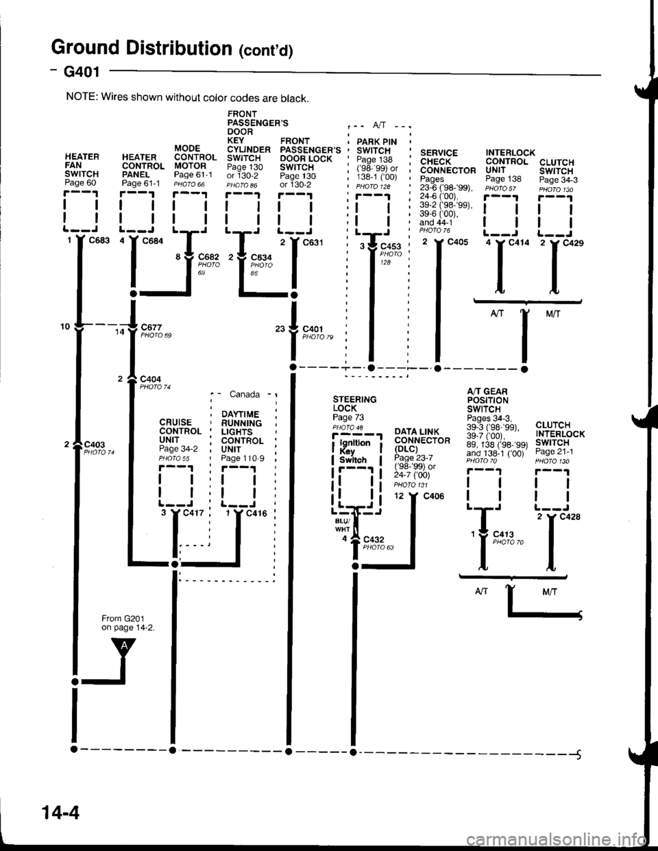
Ground Distributior (cont'd)
- G401
CLUTCHswtTcHPage 34-3
tl
tl
'l**
A/T GEARPOStTTONSWITCH
139""i#;3a, cLUrcH
ig.ii,oor.--" TNTERLOCK
89, 138 (rss- 99t lwlTcHand 138-1 { 00) Page zl-lPHO|OTo PHOfa 130
r--1 r--1
lttl
ttlll-J t--J
| 2 rc428'Y 9:t:,2." I
ttI,L
SERVICE INTERLOCKCHECK CONTROLCONNECTOR UNITPages Page 13823-6 ( 98-�99), PHoro5z24,6 ('00), i--t
iifiii;"' ! !PHOTO 76 L__J'I*- 'l*"
I -
I
-l
ll- o------- o
FRONTPASSENGER'S .-. A,/T -..DOOR ;KEY FRONT ' PARK PtN 'CYLINDER PASSENGER'S ' SWITCHSWITCH OOOR LOCK ' Paqe 138 :Paqe 130 SWITCH I (ge ggt or ior130-2 Page t30 ; 138-1 C00) ,PHafa o6 or 130-2 | pHaro 12a
!.--.! r--1 , r--1 :I | | | ;l | :
| | I | ;t | ;tT' t^-.--i^- , LrJ
"I ^^^-
z
l
t'or' : tY'"*u"" :'Yk91i t ' I'zi :a';"'" I : I
I I :lErl
"1i,.
| .
NOTE: Wires shown without color codes are black.
c403
STEERINGLOCKPage 73'i!Y-', PAIA,LT$
| . i ;;":,;i;
;p,'nron i ffi."ro*Switch I Page 23-7
!'---'' i !i:; iSii'
);
DAYTIMERUNNINGLIGHTSCONTROLUNITPage 110-9
tl
tl
't Y c41(
Canada
\YTIME
Page
I
I12 Y C406
c41
o
a
Llrri.i
i'#!"..,'lgl::""
14-4
Page 1429 of 1681
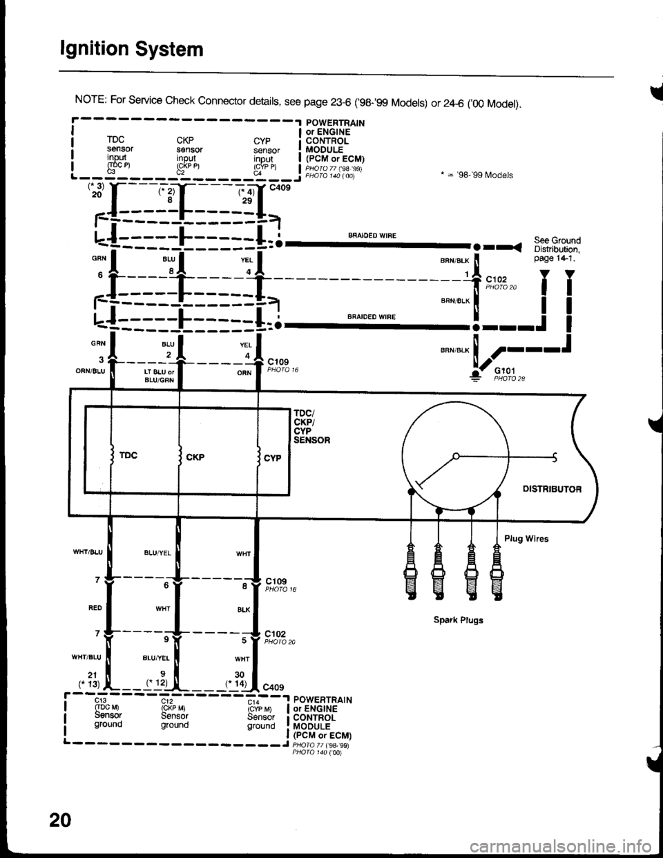
lgnition System
INorE: For service check connector details, see page 23-6 ('98-99 Models) or 2zl-6 ('00 Model).
POWERTRAINI a oielcirs '-"
rDc cKp cyp i coNTRoLsensor sensor sensor ! MODULEinout inout intu,t | /PCM.ri! input input inDut | (pCM or ECM)I g"oc et !cj
u"n,"." ! ----t
:jl--Jt---r-4,*"
"""*-Lf;
'':[:-==1-I=-==g=,-
u-{:::::L:::::+=i--- ""^".:-I'
.rr. s::3-.-:
;f:===-l_=* -=-f,*,,'fT
L-f--====E=--==i.l ""'"'"*'"'
=="=-'!---.!
I
-A 2r .|--___-OFNi 8LU II LT 8LU orI BLU/GRN
----o A c';;? F;o''","i:- F,to,l.,
Plug Wires
- - - -"-'lg- - - - - -^11 ct og
Spark Plugs
' Y-----rV-
- - - - ;V t#'",.
WHT.BLU ll BLU,"YEL I wHT
,. ?1, L--rrl:-,!-__,. ?Ll.oo,
cr3 c12 - - -.,,--a POWERTRATN(Dc Mr rckp M) icrb 6 | or ENGINEuensor Sensor Sensor i coNTRoLground ground grouno !laODuLi
20
Page 1441 of 1681
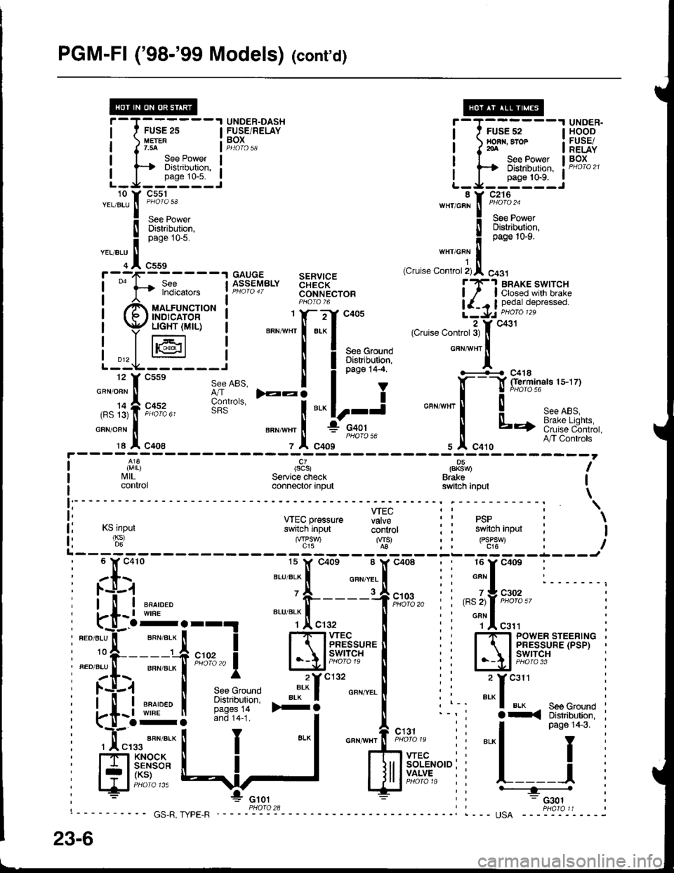
PGM-Fl ('98-'99 Models) (cont'd)
FUSE 2s
See PowerDistribution,
L_J__':n1:'_.:
i-T;;,;,---l HSBE'I nonr. sror : FUSE/I J roA I RELAYI I See Power I BOx
i ts Distribution, ! PHoro2t
L_J__0"n" to'n_..i
UNDER-DASH T-T------'I UNDER-FUSE/RELAY I ' FUSEs2 IHOODtuErER : BOX ! nonn.sror : FUSETr.3A Jp4oro5q I I2oA I RELAY
uauuE sERvtcEASSEMBLY aHidK- lT'! BRAKE swtrcHPHaro4T coNNEcroR ! / I closed wilh brakeP1oro 76 | {_. I pedat depressed.1 Y- -:-'Y .:rnE a \1,. DHOIO 129i 66g"; ilti5Xx+15l'""
I PHoroT6
ll^3j l;i,X|,io'"*".
i ry/,-'Em.dui6 | *";Xf-".'{'*',.."".*,'",-A*f.i.";"'"
Lt*F,--;J^,,
I i**''i
";\&**"**
| li'l|l (scs) pP8nu I
I I'illL. Service check Brake Ii control connector input switch inpul \
i: wEcpressure fiff ii psp : \
lj rslnpur s*[cninput- ii'iiror : i switch inpur : I
fi (6:) '"f'?-) %-' : : FJ:*t : iL------- t-L---J
;tx;
"-'TJ.!.
"oo,
: :[:"': l. -u-.1
i[uE,
i
*"T,!. enroLxl
' -i-----1
i
".''"]rf
_ en*err I
i fi:i
-'-- !
i 'T""t """'"'- !
ilrff:;iJ:rl *:f
See ABS, I
6lt"uo,", F:i
ffi; :i
*.1
I
i ll-i ""^,"." 'fr----1f,il0,3,,
i i ,"l,fF'%%"' i, i-[- t wrne BLU BLK f ll ; ' onN I
i"..*t-T;i;;i ffiff'rul.'l ii Ej'ir1'pi='Et'x'i
I la$ I .*^*"'-" ".*'f ""'^..-.
! i i _:f
*" :
: i-[l ffir* I iii:!:i* >+i
o"n""l
i l-' "'"1 u'* - seeGround I
i
-o-: --1i i l^_^-
'1:
i-<3:"J:qT3"'i
i Hf'.!$*
ll
J
I
lJrlffi"r"",
: l__ j
, : *"* E ;; ---="*L-l
"*fiix+*,"i
i
""[
23-6
Page 1449 of 1681
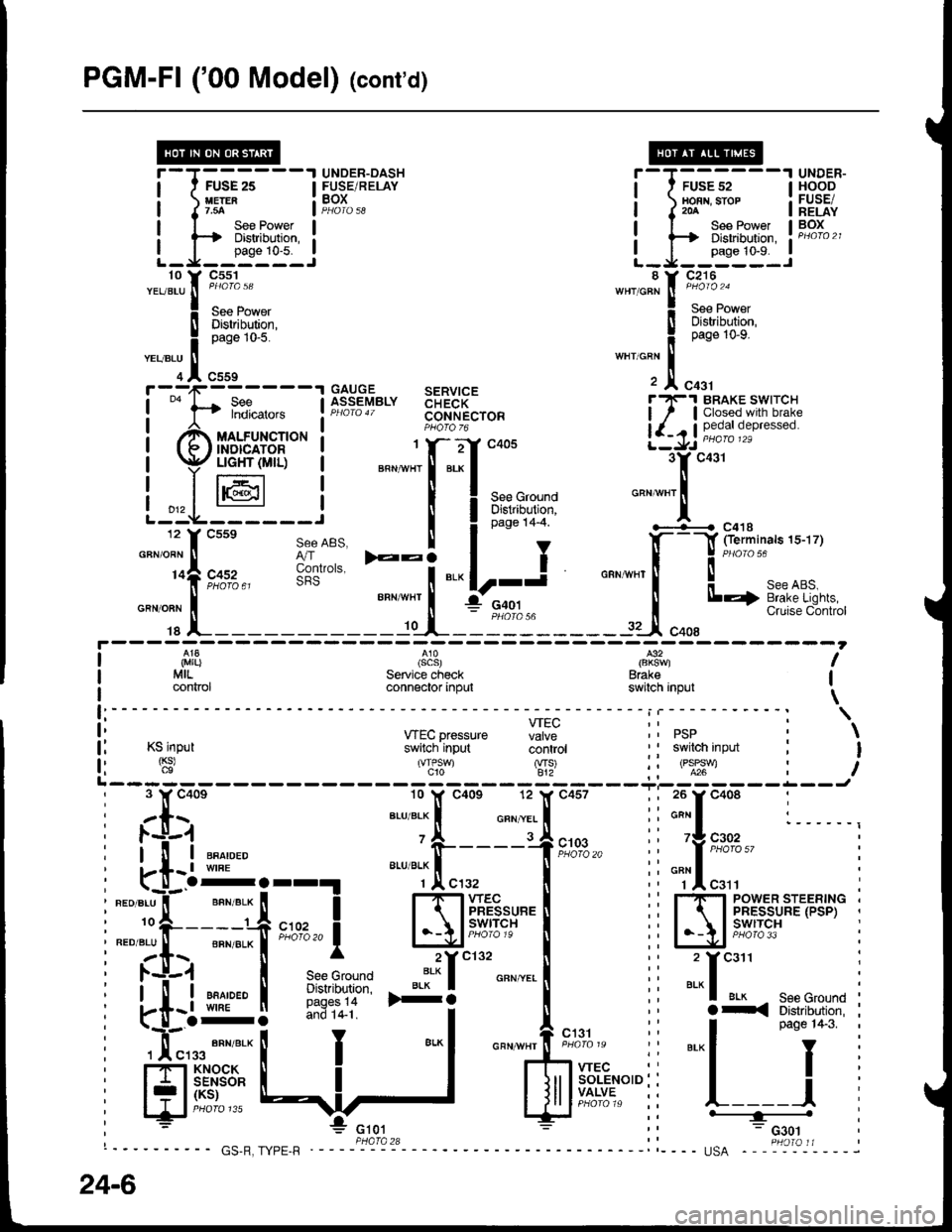
PGM-FI ('00 Model) lcont'd)
f ---,1-------1 GAITGE SERVICE
!
""
l-t fl?i*." lfr:?"'Y"'" 33FR[",o"I
| ""^,.,^
""r,o"t" t F;J$"
i Br,ffi*
-""'Ti"::"'""
'
F fl::"",.,, !f":?sy"'" $FR["r"" i7.l S[t5',"',1flJ,:1"
,ff uo.rrn"t'o* ! PHoro-6
!-r -/ ffi ore'"*"o
(f/ffirir,r$- I """-"11-"J** 3yc431
| p$tr6l:,- i *".;f:.:f
"oou ..-.t'';;;;" "
l-.L-@---i I Iar'u+t
'""*"'l
12 f csse see ABS. I I o"o" t+-+ '-+---{ c41s
"-"lt;;;"
t;dil
-:i
"."|r-i "".*[--f:il-.
iL_1
SeeABS. I t , .l(- -l fierminals 1s-17)
3o'.,", E:i
"." lr-j o"n,nn, ! J
"o'"'ur""or.
______-.f _t-_il":______rJ"oo,'*Bi""i'""*#i;
I ,i,1|}
I MrL.
I connor
(scs)Service checkconnector input
l€2
Brakeswitch inpul
I
I
\f:----- - - - - - i | - - - - - - - - - - - : \
ii *Ecpressure Hi: ii psp i \
l: Ksinput switch'input coritiot ' I swilch input : I
f l '$' 'T,'J S' ii oll:t : iL------- ------Ji 3 Y c40e 10 lf c40s 12 l( c457 ; ; 26 y c408 :, zls ar-uar-x I o"n.,.. I ii*"I :______,: l.-l-1 'A rJ
; l-'!r-i ""^,"." o-----+t;%," i" 'f ,"#!",,
: kt-l:orr!
"""*.[",.,
| :i "Tl"r" :
I ".o".u"il-' ""n".* [ I 1-1-1wec l� i rf, rsyr:sriF,.rB,]," i
i:."i:t--"# *n,,1 l-\l;tff#"'I ii IA'|5't'f3,i^'''*' i
i zt.\. [ ^ 2Yc132 [ ,' 2 Ycail :
I l.+.1 | see Grouno ':* I o"" ".. I i i ..- I :
i .-tiql i*}:11- *i
I",., ii
"'^f*il{:"{{i$l
i
i *'...#:t I
-"1 """'#*=:
ii
"'-l
pas€1+3
i
i
H** {:,]
'
$ff.':*'"ii l-=i
i
24-6
Page 1452 of 1681
- How the Circuit Works
With the ignition switch in ON (ll) or START (lll),
battery voltage is supplied through fuse 15 and the
BLK//EL wire to the vehicle speed sensor (VSS).
The sensor is grounded by the BLK wire to G101.
The speedometer and other control units in the
circuit supply about 5 volts to the ORN wire. The
vehicle speed sensor (VSS) intermittently grounds
the ORN wire which generates a pulsed signal in it.
The number of pulses per minute increases/
decreases with the speed of the car
Refer to the Service Manual (Section 23, Electrical)
for specific tests or troubleshooting procedures.
33-1
Page 1457 of 1681
Cruise Control (cont'd)
- How the Circuit Works
The cruise control system uses mechanical and
electrical devices to maintain the car's soeed at a
setting selected by the driver.
System Description
The cruise control unit receives command signals
from the cruise control main switch and the cruise
control SevBesume switch. With the ignition switch
in ON (ll) or START (lll), voltage is provided to the
cruise control main switch. When you push the
switch to on, power is provided to the cruise control
unit and the brake switch.
The cruise control unit receives information about
operating conditions from the brake switch, the
ignition control module (lCM), the vehicle speed
sensor (VSS), and the clutch switch (manual
transmission) or the A,/T gear positton switch
(automatic transmission). The cruise control unit
then sends signals to the cruise conirol actuator
which regulates the throttle position to maintain the
selected speed. The control unit compares the
aclual speed of the car to the selected speed. The
control unit then uses the result of that comoarison
to oDen or close the throttle.
The brake switch releases the system's control of
the throttle at the instant you press on the brakepedal. The switch sends a signal to the control unit
by removing power from the normally closed brake
input (GRY wire), and providing power at the
normally open brake input (GRNMHT wire). The
control unit responds by allowing the throttle to
close. The clutch switch or the A/T gear position
switch sends a "disengage" signal to the control unit
that also allows the throttle to close.
The cruise control system will set and automatically
maintain any speed above 25 mph (40 km/h). To set
it, make sure the main switch is on and the switch
indicator is on. Then, after reaching the desired
speed, press the set switch. This sends a "set"
signal to the cruise control unit which, in turn,
controls the cruise control actuator to maintain the
set soeed.
When you push the SET switch and the cruise
control system is on, the "cruise control" ON
indicator lights up.
34-4
You can cancel the cruise control system by
turning the main switch off. This removes power to
the control unit and erases the set sDeed from
memory. lf the system is disengaged temporarily
by the brake switch, or clutch switch, and the car's
speed is still above 25 mph, press the RESUME
switch: the car will automatically return to the
previously set speed.
For gradual acceleration without pressing the
accelerator pedal, push the RESUME switch and
hold it there. This will send an "acceleration" signal
to the control unit. When you release the switch, the
system will be reprogrammed tor the new speed. To
slow the car down, push the SET switch in and hold
it there. This sends a "deceleration" signal to the
control unit, causing the car to coast. When the
desired speed is reached, release the SET switch.
This reprograms the system for the new speed.
Reter to the Service Manual (Section 23, Electrical)
for specific tests or troubleshooting procedures.
Page 1460 of 1681
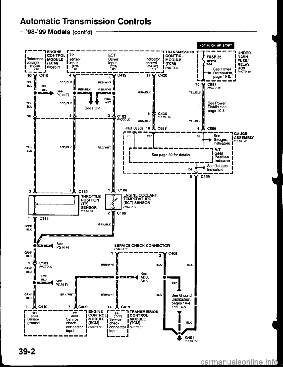
Automatic Transmission Controls
- '98-'99 Models (cont'd)
YEUatu
-ry
UNDER-DASHFUSE/RELAYBOX
SERVICE CHECK CONNECTOR
1l[----- -i-f c+os
"""t"'
I see
-^
|.EE< ABS,
i-1
Ti:
t':,;"'1...,
*";'1".,,
- sRS
""1
#t*r-^:----- ENGTNE r--:-I TRANSM|SS|ON I rI r*ib rsis, I coNTRoLl r"sb'sr I coNTRoL I i
fl i$yjHlr'!;f#n",!ffiii:' \i- !- G401- PHOTO 56
r)J-1
i*J itTffe.- ir:";-
- - - -
s:I-
- - - -
;;; I HffilEr''". i T r.s:;
- -
II voliage l{ECM) | input
I w,?- | i.o, o,, L :t - - - - - jrfl - - - - - Si
j hfiY:t'
".
i 1-%** i
l_: f, "o'oror c410 4tr-------E[c4ts 17tr' c420 LJ__HSIJ
:ii t Hb ^f'""'* ! "."".* :;;! !
';l "lz*"
-
-[ ;;
"*i*'*i[Try[",".
""."]1,**^ "'""'"!
*u*u''o
ft_ _ _____+___ _ _'lfi g;to,..,. o"n,"J, f t",",,
Page 1464 of 1681
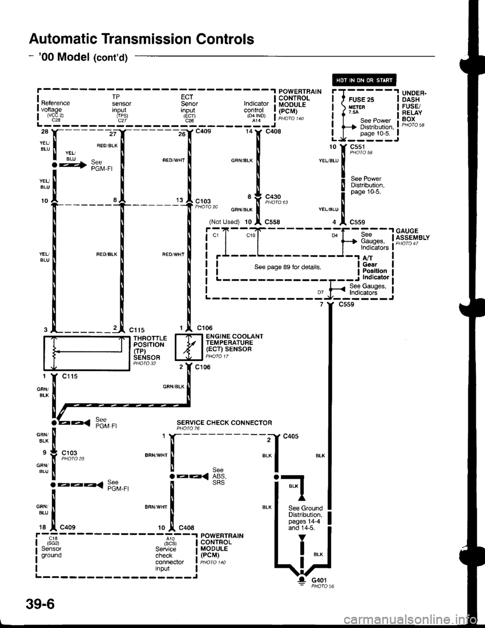
Automatic Transmission Controls
- '00 Model (cont'd)
[---;""'.f
-lc+os 141' c4o8 LJ-:*:IJ
|
:t
, ;:".1
*"",",1 "**-
I
-.11,[t*r'""
I .l ,.,1,","" .J,o*". i
r*ru;l
i.";-
- - -
Is"*
- - - - -
Fsil
- - -
;; I i.l{T'Fil^'- i I ;;
- -
I Ui3"*I voltage Inout
L js!'- - - - - - d": - - - - - 3t - - - - - roql j Hili:
i i-Ti*.*,*,, i F"H*i,'ll-------zrI_------16'rc4os 14tr' c408 LJ_j*::J
:tt, I ".ou.*l I I
r rii ^ r "."-,. r ^""",. r ". ::[ 9#3-
**[
[ [ X"., !r*g+;l"f-----
t
't
l;:,.il*[;,;
""T1",,,""
! ! !i;T-"{_
___-}.[1dnw'"t*il *"*-l "'o*n'l i'I---L-
I I NLi::--::::-:=a-*$$ti
.l_______l ",,, ,l ",,.
'r "*'
I_ITI ENGINE COOLANT
iddirioil I Jr l,.g:tilu;SENSOR lJJal PHora 17
c106
GFN/BLK
SERVICE CHECK CONNECTORPHOIO 76
-"^,:,[
.:
"{
'T[_:'*' "..1
;*liil, lFffi*'" I
c405
BLI
BLK I
I'
See GroundDistribution,pages 14-4and 14-5.
V
I ..
G401
39-6
Page 1468 of 1681
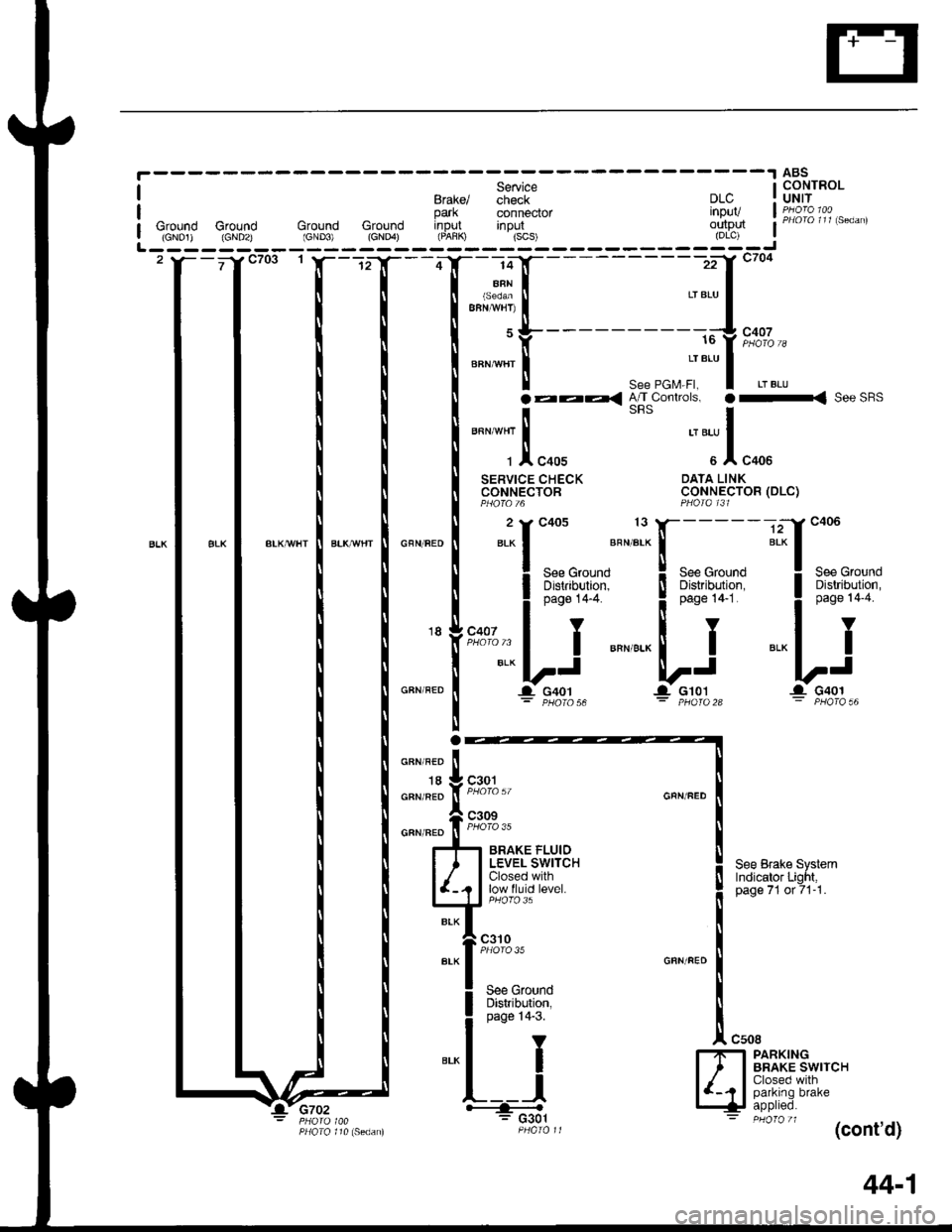
________r 49sI Service I CONTROLBtaxel check DLC : UNIT
r?.:y" t F73il3"11,".o^,park connector inPUVGround Ground Ground Ground input inout outp$(GNo1) {GND2} (GND3) (cNo4) (FAfiK) {scs) (DLc)| (cNo1) (GNDzl (GND3) (cNo4) (FAfiK) {scs) (DLc) !L------- -------J2 y-- ja c7o3 t l- --r-f --4 f - 14 y- - -zil czot'T
T;ui[
----.,-"'{''�*
I |"""'if--- "","-Jt :*
N |
*:[-"-:*ttn"";"'i:
l;l-f*::::ffff'a
:::ffi*
',.-,
'"n"'"lr=***u*,^
[ | ".-lt*'* o"^^.o IlIl
I I ii;*r;,i*' I
i ! l*; .t,"uo,
i I *"1 I rrlBAl['JS,n,,""d i I i l7t-lc'o."0*nn
# t+ rat+di+**"
44-1
Page 1471 of 1681
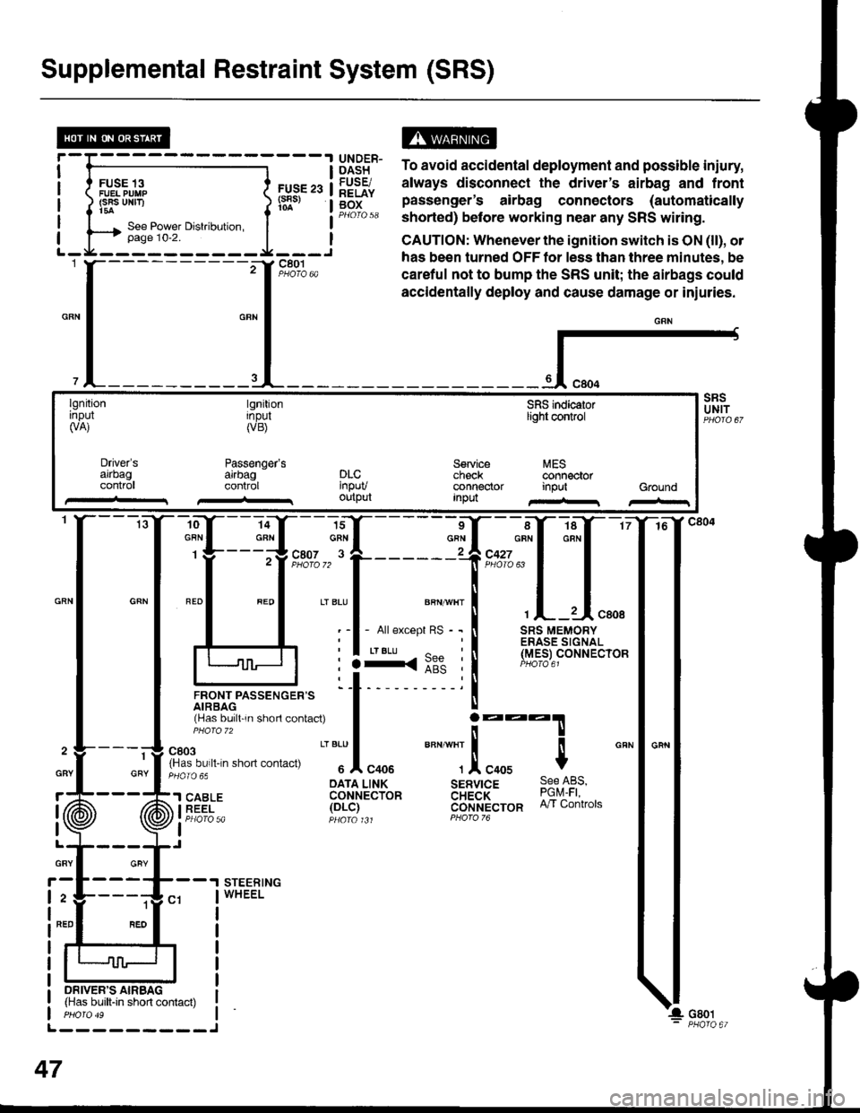
Supplemental Restraint System (SRS)
FUSE 13FUEL PUIIP(SRS UNF)t5a
FUS€ 23(s8s)
ts13t5" To avoid accidental deployment and possible iniury,
lq9Fr. always disconnect the driver's airbag and frontg[f" pas"Lnger's airbag connectors (automaticallyPHorQ 58 shorted) before working near any SRS witing.
CAUTION: Whenever the ignition switch is ON (ll), ol
has been turned OFF tor less than three minutes, be
careful not to bump the SRS unit; the airbags could
accidentally deploy and cause damage or iniuries.
{-
lgnitionrnpul(VA)
tgnitionInpul(VB)
Passenger'sarrbagcontrol
SFIS indicaiorlight control
Service MEScheck @nnectorconnector input GroundInpu
Driver'sarrbagconlr0lDLC'npuvoutput
-ro--Y---la-Y--- 16
:ffi*f:ffq
lJnor,rrpassencen= 'l t- 'i
rHas bu,ll 'n shorl contac0
I j:::T
fn'"o"t. n-n .non "on,""u
" "'Jl
"oou
""" ""]
.!, "oou $
cRN
: :3<::" :l (Y.e_er
oArA LINK sERvrcE 9qe l-qs,'l SABLE coHrecibn aH;a'i- ?9q1i iEEi- 1ot-i1 cijrlt't'ecron n/r contrors
I Pt:OfO 5a pqara t Jt PForo 76
I
STEERINGWHEEL
1
GRY
ON|vER'S AIRBAG(Has built-in short contact)
L---------J
47
GBY
r
I
I
GRY
2
NED