check engine HONDA INTEGRA 1998 4.G Manual PDF
[x] Cancel search | Manufacturer: HONDA, Model Year: 1998, Model line: INTEGRA, Model: HONDA INTEGRA 1998 4.GPages: 1681, PDF Size: 54.22 MB
Page 315 of 1681
ldle Control System
Fast ldle Thermo Valve (A/T model onlylFast ldle I nermo valve (A/ | mooel
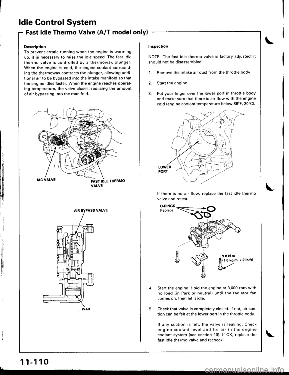
Description
To prevent erratic running when the engine is warming
up. it is necessary to raise the idle speed. The fast idle
thermo valve is controlled by a thermowax plunger.
When the engine is cold, the engine coolant surround-
ing the thermowax contracts the plunger, allowing addi
tional air to be bvoassed into the intake manifold so that
the engine idles taster. When the engine reaches operat-
ing temperature, the valve closes. reducing the amount
of air bypassing into the manifold.
FAST IDLE THERMO
VALVE
VALVE
wAx
Inspection
NOTE: The fast idle thermo valve is factory adiusted; it
should not be disassembled.
1. Remove the intake air duct from the throttle body.
2. Start the engine.
3. Put your finger over the lower port in throttle body
and make sure that there is air flow with the engine
cold {engine coolant temperature below 86'F, 30"c).
LOWERPORT
lf there is no air flow, replace the last idle thermo
valve and retest.
Start the engine. Hold the engine at 3,000 rpm with
no load (in Park or neutral) until the radiator fan
comes on, then let it idle.
Check that valve is completely closed. lf not, air suc-
tion can be felt at the lower port in the throttle body.
l{ any suction is felt, the valve is leaking. Check
engine coolant level and for air in the engine
coolant system (see section 10). It OK, replace the
fast idle thermo valve and recheck.
5.
{1.0 kg.m,7.2lbftl
l
11-110
lL.�
Page 316 of 1681
ldle Speed Setting
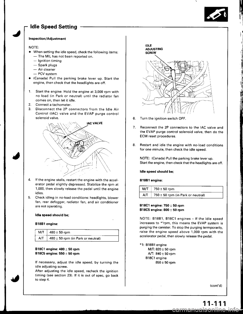
IDLEADJUSTINGSCREW
7.
6.Turn the ignition switch OFF.
Reconnect the 2P connectors to the IAC valve and
the EVAP purge control solenoid valve, then do the
ECM reset procedures.
Restart and idle the engine with no-load conditions
for one minute, then check the idle speed.
NOTE: (Canada) Pullthe parking brake lever up.
Start the engine, then check that the headlights are off.
ldle speed should be;
Bl88l €ngine:
Mfi750 i 50 rpm
A/T750150 rpm (in Park or neutral)
818C1 engine:750 i 50 rpm
818C5 engine: 800 i 50 rpm
NOTE: 81881, Bl8Cl engines - It the idle speed
increases to *1rpm, this means the EVAP system ispurging the canister. To stop the purging termporarily.
raise the engine speed above 1,000 rpm with the
accelerator pedal, then slowly release the pedal.
*1: 81881 engine
M/T: 820 i 50 rpm
Ay'T: 840 t 50 rpm
818Cl engine
850 I 50 rpm
(cont'd)
Inspection/Adiustmont
NOTE:
. When setting the idle speed, checkthe following items:- The MIL has not been reported on.- lgnition timing
Spark plugs- Air cleaner- PCV system
. (Canada) Pull the parking brake lever up. Start the
engine, then check that the headlights are off.
1. Start the engine. Hold the engine at 3,000 rpm with
no load (in Park or neutral) until the radiator fan
comes on, then let it idle,
Connect a tachometer.
Disconnect the 2P connectors from the ldle Air
Control (lAC) valve and the EVAP purge control
solenoid valve.
2.
5.
if the engine stalls, restan the engine with the accel
erator pedal slightly depressed. Stabilize the rpm at
1,000, then slowly release the pedal until the engine
idles.
Check idling in no-load conditions: headlights, blower
fan, rear defogger, radiator fan, and air conditioner
are not ope€tlng.
ldlo speed should be;
B188l engine:
Mlf480 :l 50 rpm
A/T480 i 50 rpm (in Park or neutral)
B18C1 engine: /t80 t 50 rpm
818C5 sngine:550 t 50 rpm
lf necessary, adjust the idle speed, by turning theidle adjusting screw.
After adjusting the idle speed, recheck the ignition
timing {see section 23). lf it is out of spec, go back
to steo 4.
Page 317 of 1681
ldle Control System
ldle Speed Setting (cont'dl
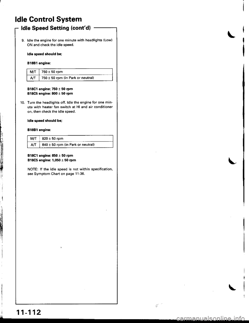
ldle the engine for one minute with headlights (Low)
ON and check the idle speed.
ldle 3peed should b€;
B1881 engine:
MIT750 t 50 rpm
750 i 50 rDm (in Park or neutrall
818C1 engine: 7501 50 nm
818C5 engine: 8001 50 rpm
Turn the headlights off. ldle the engine for one min-
ute with heater fan switch at Hl and air conditioner
on, then check the idle speed.
ldl. spood should be;
Bl8Bl ongin.:
M/T820 i 50 rpm
lvT840 t 50 rpm (in Park or neutral)
818C1 €ngino: 850 i 50 rpm
818C5 engino: 1,050 t 50 rpm
NOTE: lf the idle speed is not within specification.
see Symptom Chart on page 1!-36.
\
L
i
lIh:
lffiiltfl!
ffi
| 11-112
\
I
Page 322 of 1681
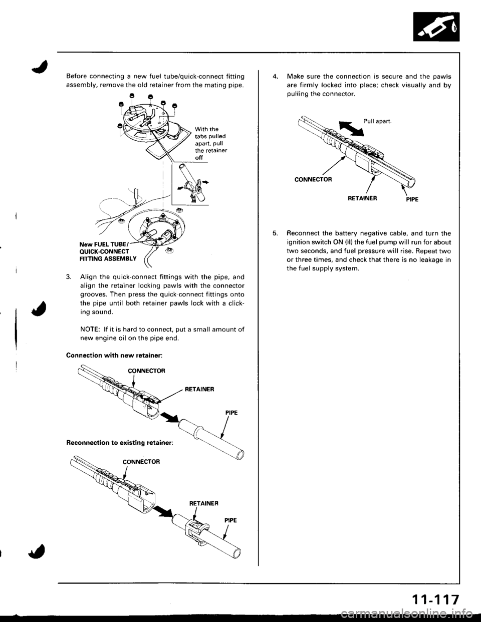
Before connecting a new fuel tube/quick-connect fitting
assembly, remove the old retainer from the mating pipe.
With rhetabs pulled
apart, Pullthe retaineroff
New FUEL TUBE/OUICK.CONNECTFTflNG ASSEMBLY
3. Align the quick-connect fittings with the pipe, and
align the retainer locking pawls with the connector
grooves. Then press the quick connect fittings onto
the pipe until both retainer pawls lock with a click-
Ing souno.
NOTE: lf it is hard to connect, put a small amount of
new engine oil on the pipe end.
Connection with new retainer:
5.
Make sure the connection is secure and the pawls
are lirmly locked into place; check visually and by
pulling the connector.
RETAINER
Reconnect the battery negative cable, and turn the
ignition switch ON (ll) the fuel pump wjll run for about
two seconds, and fuel pressure will rise. Repeat two
or three times, and check that there is no leakage in
the fuel supply system.
11-117
Page 325 of 1681
I
Fuel Supply System
Fuel Injector (cont'dlFuel Pressure Regulator
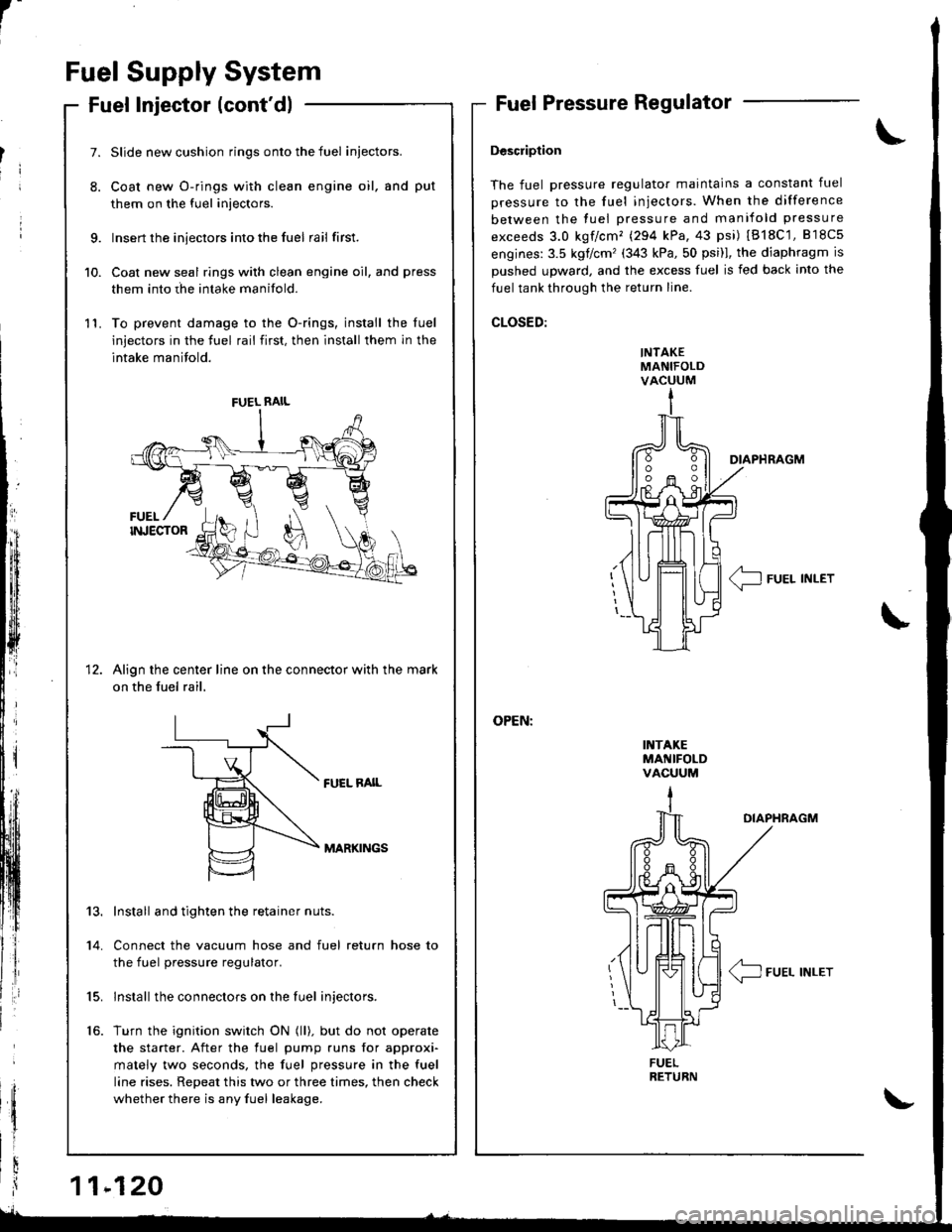
Description
The fuel pressure regulator maintains a constant fuel
pressure to the fuel injectors. When the difference
between the fuel pressure and manifold pressure
exceeds 3.0 kgf/cm'� (294 kPa,43 psi) IB18C'1,818c5
engines:3.5 kglcm'(343 kPa,50 psi)l, the diaphragm is
Dushed uDward, and the excess fuel is fed back into the
fuel tank through the return line.
CLOSED:
INTAKEMANIFOLDVACUUM
I1{TAKEMANIFOLDVACUUM
DIAPHRAGM
< IFUEL INLET\-
\
OIAPHRAGM
/4_\T-J FUEL INLET
9.
10.
11.
7.
8.
1t
Slide new cushion rings onto the fuel iniectors.
Coat new O-rings with clean engine oil, and put
them on the fuel injectors.
Insert the injectors into the fuel rail first.
Coat new seal rings with clean engine oil, and press
them into rhe intake manifold.
To prevent damage to the O-rings, install the luel
injectors in the fuel rail first, then install them in the
intake manifold.
Align the center line on the connector with the mark
on the fuel rail,
FUEL RAIL
MARKINGS
13.
14.
15.
16.
Install and tighten the retainer nuts.
Connect the vacuum hose and fuel return hose to
the fuel pressure regulator.
lnstall the connectors on the fuel injectors.
Turn the ignition switch ON (ll). but do not operate
the starter. After the fuel pump runs for approxi'
mately two seconds, the fuel pressure in the fuel
line rises. Repeat this two or three times, then check
whether there is any fuel leakage.
FUEL RAIL
FUEL
Page 326 of 1681
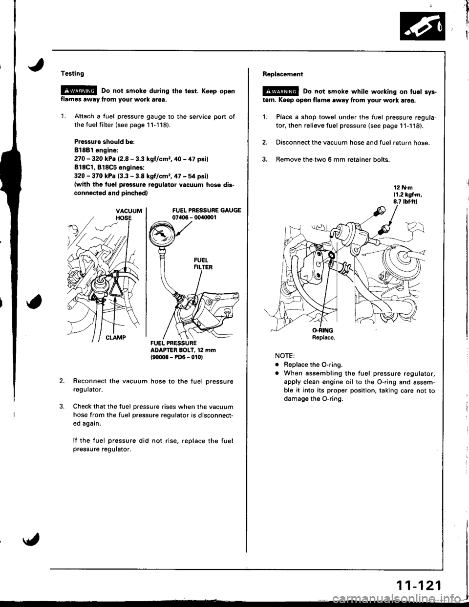
Testing
@G Do not smoke during the test. Keep opon
flames away lrom your work ar€a.
1. Attach a fuel pressure gauge to the service port of
the tuel filter (see page 11-118).
Pr€ssurs should be:
8188l €ngine:
27O - 320 kPa 12.8 - 3.3 kgl/cmr. 40 - 47 psil
818C1, 818C5 engines:
320 - 370 kPa (3.3 - 3.8 kgrf/cm,, 47 - 54 psi)
{with tho fuol pfossure regulatot vacuum hose dis-
connected and pinchsd)
FUEL PRESSURE GAUGE074t 6 - 004{1001
ADAPTER BOIT, 12 mm(9txt08-PD6-0101
Reconnect the vacuum hose to the fuel pressure
regulator.
Check that the fuel pressure rises when the vacuum
hose from the fuel pressure regulator is disconnect-
ed again.
lf the fuel pressure did not rise, replace the fuelpressure regulator.
VACUUM
FUEL PRESSURER€place.
AA
,il
I
I
Replacem6nl
@ Do not smoke while working on tucl sys-
tem. Keep open flamc away from your work area.
1. Place a shop towel under the fuel pressure regula-
tor, then relieve fuel pressure (see page 11-1'18).
2. Disconnect the vacuum hose and fuel return hose.
3. Remove the.two 6 mm retainer bolts.
NOTE:
. Replace the O-ring.
o When assembling the fuel pressure regulator,
apply clean engine oil to the O-ring and assem-
ble it into its proper position, taking care not to
damage the O-ring.
r1
i
i
11-121
Page 329 of 1681
1L
i
!i
!
{
Fuel Supply System
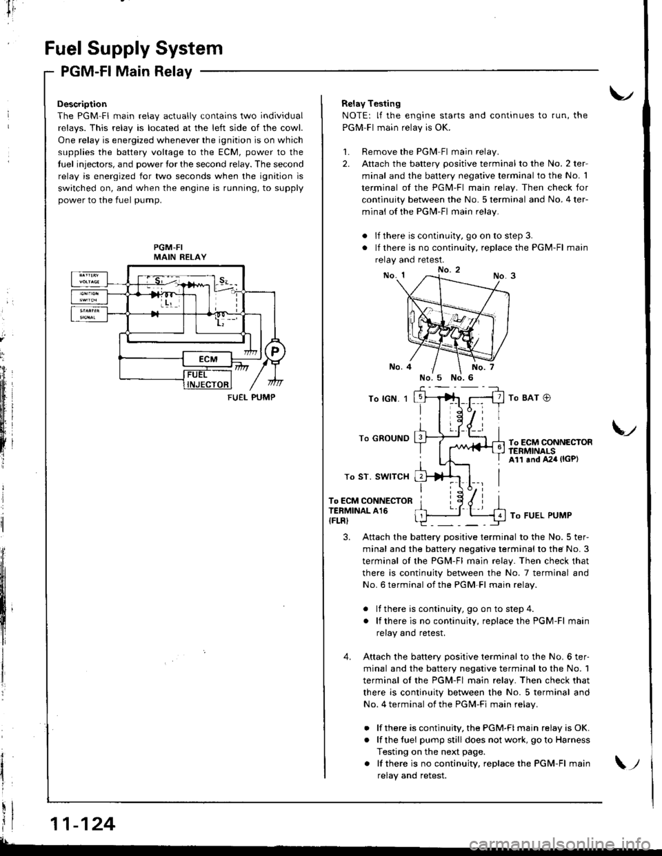
PGM-Fl Main Relay
Description
The PGM Fl main relav actuallv contains two individual
relavs. This relav is located at the left side of the cowl.
One relay is energized whenever the ignition is on which
supplies the battery voltage to the ECM, power to the
tuel injectors, and power tor the second relay. The second
relay is energized for two seconds when the ignition is
switched on, and when the engine is running, to supply
power to the fuel pump.
PGM-FIMAIN RELAY
11-124
FUEI- PUMP
Relay Testing
NOTE: lf the engine starts and continues to run, the
PGM-Fl main relay is OK.
1. Remove the PGlvl Fl main relay.
2. Attach the battery positive terminal to the No. 2 ter-
minal and the battery negative terminal to the No. 1
terminal of the PGM-Fl main relay. Then check for
continuity between the No. 5 terminal and No. 4 ter-
minal of the PGN4-Fl main relay.
. lf there is continuity, go on to step 3.
. lf there is no continuity, replace the PGM-Fl main
relay and retest.
To lGN. 1
To GROUND
To ST. SWITCH
To ECM CONNECTORTERMINAL A16
{FLRI
To BAT @
To ECM CONNECTORftNMNALSAll and A24 (lGP)
V
To FUEL PUMP
3. Attach the battery positive terminal to the No. 5 ter-
minal and the battery negative terminal to the No. 3
terminal of the PGM-Fl main relay. Then check that
there is continuity between the No. 7 terminal and
No. 6 terminal of the PGM-Fl main relav.
. lf there is continuity, goon tostep4.
. lf thereis nocontinuity, replacethe PGM-Fl main
relay and retest.
4. Attach the batterv oositive terminal to the No. 6 ter-
minal and the battery negative terminal to the No. 1
terminal ol the PGM-Fl main relay. Then check that
there is continuity between the No. 5 terminal and
No. 4 terminal of the PGM-Fi main relav.
. lf there is continuity, the PGM-FI main relay is OK.
. lf the fuei pumpstill does not work, goto Harness
Testing on the next page.
. lf thereis nocontinuity, replacethe PGM-Fl main
relav and retest.\;
Page 330 of 1681
I
tr,
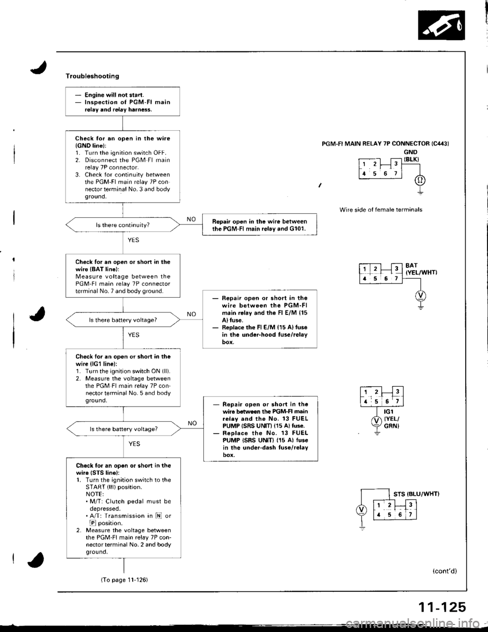
- Engine will not start.- Inspection of PGM-FI mainrelay and relay harne$.
Check lor an open in the ware{GND line}l1. Turn the ignition switch OFF.2. Disconnect the PGM Fl mainrelay 7P connector.3. Check for continuity betweenthe PGM'FI main relay 7P connector terminal No. 3 and bodyground,
Repair open in the wire betweenthe PGM-Fl main relay and G101.
Check for an open or shon in thewire {BAT line)rMeasure voltage between thePGM-Fl main relay 7P connectorterminal No.7 and body ground.- Fepaii open or short in thewire between the PGM-FImain rel6y and the Fl E/M 115A) tuse.- Replace th€ Fl E/M {15 A)fusein the under-hood tuse/relay
ls there battery vohage?
Check foi an open or shori in thewire (lG1 line):1. Turn the ignition switch ON (ll).
2, Measure the voltage betweenthe PGM Fl main relay 7P con-nector terminal No. 5 and bodyground,R€pair open or short in thewire betwo€n the PIGM-FI mainrelav and the No. 13 FUELPUMP ISRS UNIT) (15 Altuse.ReDlace the No. 13 FUELPUMP ISRS UNID (15 Al fusein the under-dash tuse/relayoox,
Check for an open or short in thewire {STS linel:1. Turn the ignition switch to theSTART { lll) position.NOTE:. M/T: Clutch pedal must beoepresseo.. A/T: Transmission in ld or
E position.2. Measure the voltage betweenthe PGM-FI main relay 7P con-nector terminal No. 2 and bodyground,
Troubleshooting
'l RELAY 7P CONNECTOR
GND
t .--.-l T;-l IBLK)L' 'r I" T----
lr s o rl A
+
Wire side o{ female termanals
8AT(YEL/WHT)
STS {BLU/WHTI
(cont'd)
(To page11- t 26)
11-125
Page 335 of 1681
l-
Intake Air System
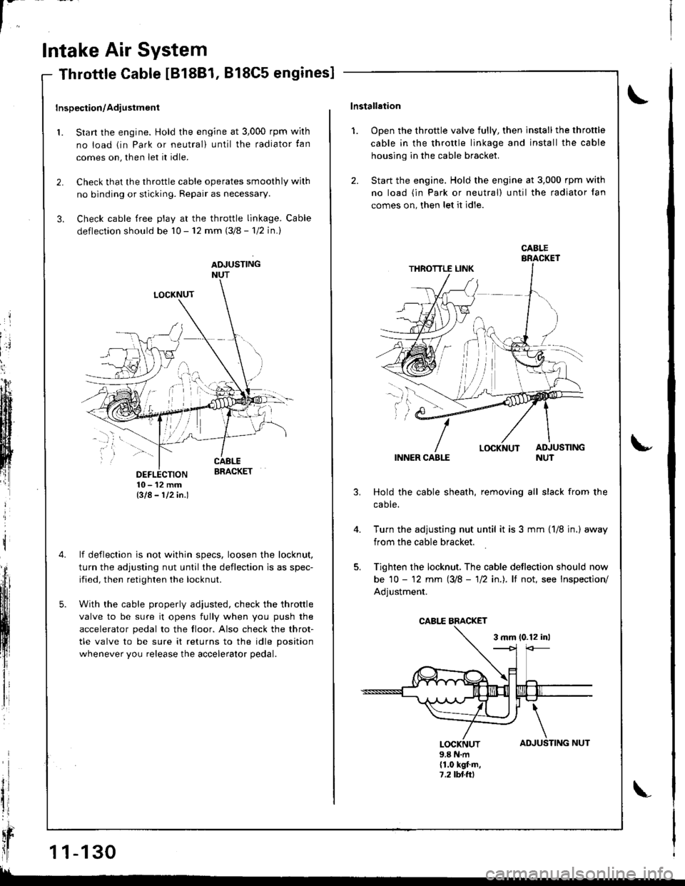
LOCKNUT
DEFLECTION10-12mmBIA- 112in.l
lf deflection is not within specs, loosen the locknut,
turn the adjusting nut until the deflection is as spec-
ified, then retighten the locknut.
With the cable properly adiusted, check the throttle
valve to be sure it opens fully when you push the
accelerator pedal to the floor. Also check the throt-
tle valve to be sure it returns to the idle position
whenever you release the accelerator pedal.
Throttle Cable IB18B1, 818C5 engines]
Inspection/Adiustment
1. Start the engine. Hold the engine at 3,000 rpm wirh
no load (in Park or neutral) until the radiator tan
comes on, then let it idle.
2. Check that the throttle cable operates smoothly wilh
no binding or sticking. Repair as necessary.
3. Check cable free play at the throttle linkage. Cable
deflection should be 10 - 12 mm (3/8 - 'l12 in.l
ADJUSTINGNUT
t
il
qr
ll1 1-130
!!
TING NUT
\lnstallation
1. Open the throttle valve fully, then install the throttle
cable in the throttle linkage and install the cable
housing in the cable bracket.
2. Start the engine. Hold the engine at 3,000 rpm with
no load (in Park or neutral) until the radiator fan
comes on, then let it idle.
INNER CABLE
Hold the cable sheath, removing all slack from the
caote.
Turn the adjusting nut until it is 3 mm {1/8 jn.) away
from the cable bracket.
Tighten the locknut, The cable deflection should now
be 10 - '12 mm (3/8 - 'll2 in.). lf not, see Inspection/
Adjustment.
3 mm 10.12 inl
u
4.
AD
\
JUSLOCKNUT9.8 N.m(1.0 kgt.m,7,2lbl.ttl
CABI.E
CABI,E BMCKET
Page 336 of 1681
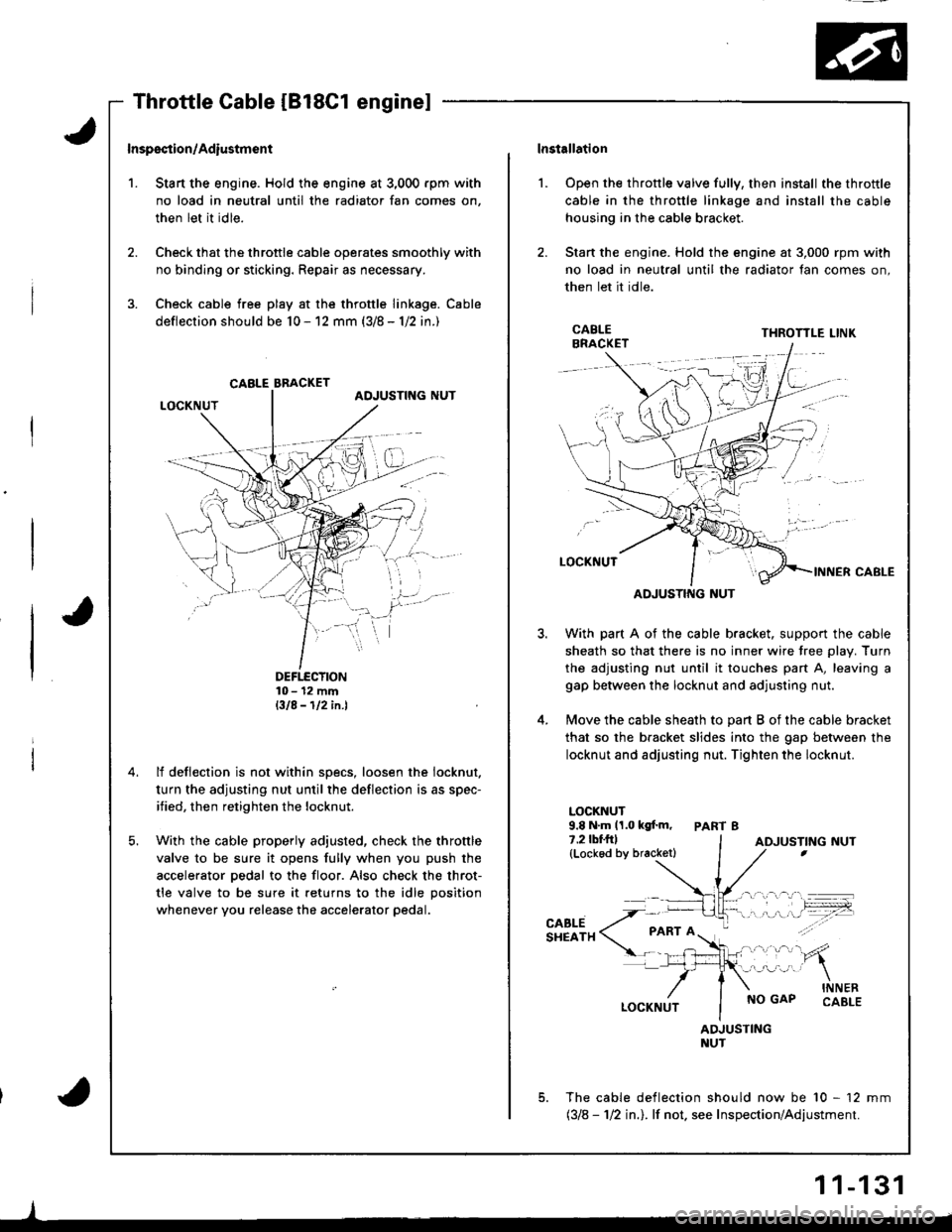
't.
Inspsction/Adiustmsnt
Stan the engine. Hold the engine at 3,000 rpm with
no load in neutral until the radiator fan comes on,
then let it idle.
Check that the throttle cable operates smoothly with
no binding or sticking. Repair as necessary.
Check cable free play at the throttle linkage. Cable
deflection should be 10 - 12 mm (3/8 - 1/2 in.)
DEFTECTION10- 12 mmBIA-112in.l
lf deflection is not within specs, loosen the iocknut.
turn the adjusting nut until the deflection is as spec-
ified, then retighten the locknut.
With the cable properly adjusted, check the throttle
valve to be sure it opens fully when you push the
accelerator pedal to the floor. Also check the throt-
tle valve to be sure it returns to the idle position
whenever you release the accelerator pedal.
CABLE BBACKET
lnstallation
Open the throttle valve fully, then install the throttle
cable in the throttle linkage and install the cable
housing in the cable bracket.
Stan the engine. Hold the engine at 3,000 rpm with
no load in neutral until the radiator fan comes on,
then let it idle.
l.
3.
5.
CABLEBRACKETTHROTTLE LINK
ADJUSTING NUT
With part A of the cable bracket. support the cable
sheath so that there is no inner wire tree plav. Turn
the adjusting nut until it touches part A, leaving a
gap between the locknut and adjusting nut.
Move the cable sheath to oart B of the cable bracket
that so the bracket slides into the gap between the
locknut and adjusting nut. Tighten the locknut.
LOCKNUT9.8 N.m 11.0 kgf.m, PART 87.2lbf.frl(Lockod by bracketl
CABLESHEATH
NO GAPINNERCABLE
ADJUSTINGNUT
The cable deflection should now be 10 - 12 mm(318 - 112 in.l. lf not. see Inspection/Adjustment.
ADJUSTING NUT
1 1-131