HONDA INTEGRA 1998 4.G Workshop Manual
INTEGRA 1998 4.G
HONDA
HONDA
https://www.carmanualsonline.info/img/13/6069/w960_6069-0.png
HONDA INTEGRA 1998 4.G Workshop Manual
Trending: trunk release, clock setting, catalytic converter, fuel pressure, sunroof, cooling, dashboard warning lights
Page 1321 of 1681
(
Wipers/Washers
Circuit Diagram
UNDEF.OASHFUSEiRELAYSOX
NTE NMI]TEI'IIWPES RELAYCIFCUIT/ In lhe inr6grar6d \ @nlrolun( I
IGNITIONSW TCHUNDER,HOOD FUSE/RELAY BOX
GRI]/BLK
GFIVBLK
WINDSHIELO WPENJWASHER SWITCH
BLK
G201G401
* : Wilh combined washer-wiDer ooeralion
BLI(GRN
I
A w'',,os"( M ) WASHER
Y
MoroF
8LK
I
G301
23-266
I
Page 1322 of 1681
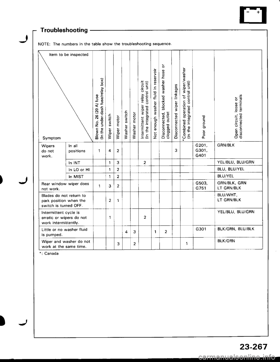
NOTE: The numbers in the table show the troubleshooting sequence
Item to be inspected
Symptom
s
9\
<-tr
Rir
2E
3E9c@=
o=
;
E
;3
E
B
e:'d_
>i
9o
oo
;E
9E
c
).E
z
o
3
;
t,o
q(')
E3ot
.g
;
c
.9.o
i6
cP
F!
o3cj
o)
Wipers
oo nor
ln all
positaons123
G20'l
G301
G401
GRN/BLK
ln INTI3YEL/BLU, BLU/GRN
ln LO or Hl12BLU. BLU/YEL
In MIST12BLU/YEL
Rear window wiper does
not work.2Gs03,GRN/BLK, GRN
LT GRNi BLK
Blades do not return to
park position when the
switch is turned OFF.
2
BLU/WHT,
LT GRN/BLK
Intermittent cycle is
erratic or wipers do not
work intermittently.
aYEL/BLU, BLU/GBN
Little or no washer fluid
rs pumped.43I2G301BLK/GRN, BLU/BLK
Wiper and washer do not
work at the same time.321BLK/GRN
*: Canada
Troubleshooting
23-267
Page 1323 of 1681
Wipers/Washers
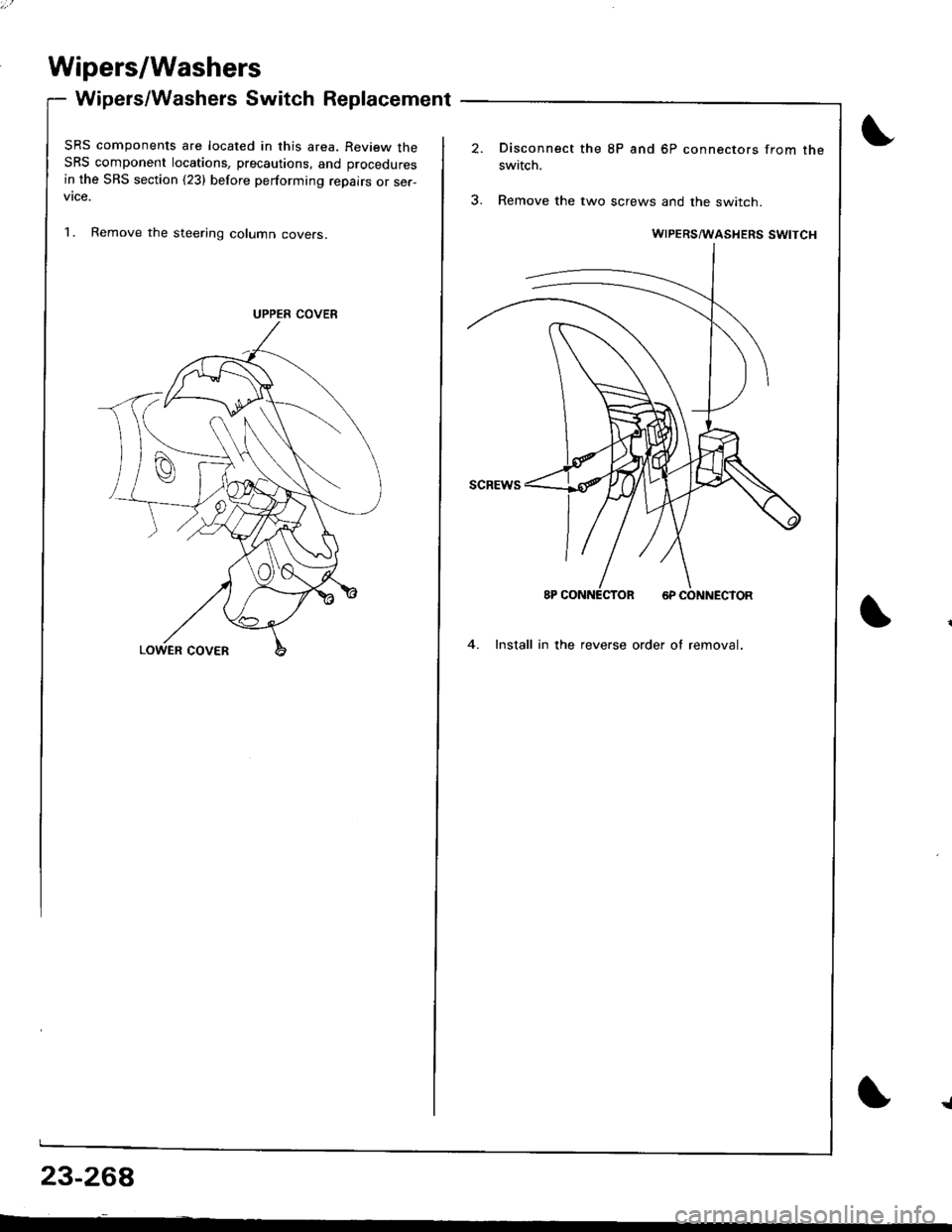
Wipers/Washers Switch Replacement
SRS components are located in this area. Review theSRS component locations, precautions, and procedures
in the SBS section (23) before performing repairs or ser-vtce.
1. Remove the steering column covers.
UPPER COVER
Disconnect the 8P and 6P connectors from the
switch.
3. Remove the two screws and the switch.
4. Install in the reverse order of removal.
{
23-26A
Page 1324 of 1681
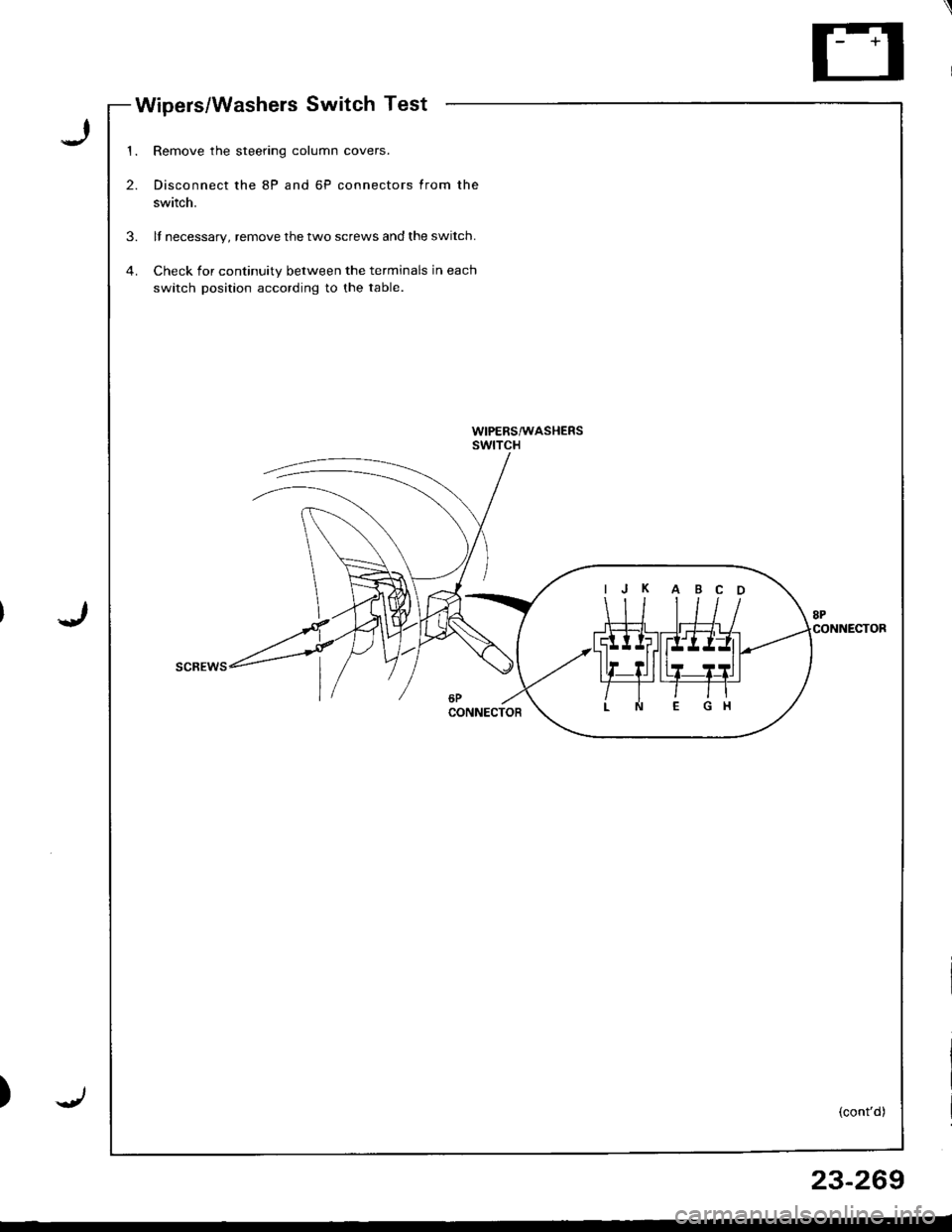
Wipers/Washels Switch Test
I
J
)
1.
2.
Remove the steering column covers.
Disconnect the 8P and 6P connectors from the
switch.
ll necessary, remove the two screws and the switch.
Check for continuity between the terminals in each
switch position according to the table.
3.
WIPERS/wASHERSswtTcH
(cont'd)
IJ K A BC O
23-269
Page 1325 of 1681
Wipers/Washers
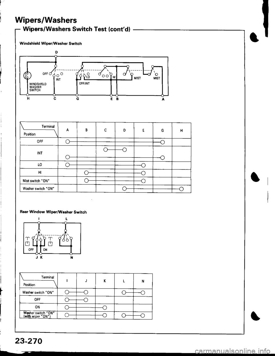
Wipers/Washers Switch Test (cont'd)
WindEhield Wiper/Wssher Switch
o
EB
R€ar Window Wiper/Wssher Switch
IL
JK
,, o"di)"------
wm+* I-
i- 4l
rt--"J
OFF/INT
Terminal
t"'-*
--_\cnEH
o--o
INT
o-
o----o
--o
LOo---o
HIG---o
Mist switch '0N'o----o
Washef switch "0N"o----o
qI{
tt(x! - --- ---- --1r, \',h.l Xr'. )a
lJ"q
Teminal
t".,r-----__\JKN
Washer switch "0N'o----oo---o
OFFo----o
ONo----o
Washer switch "01,1'
&tlwiper'0N")o----oG----o
.f
23-270
I--�
Page 1326 of 1681
I
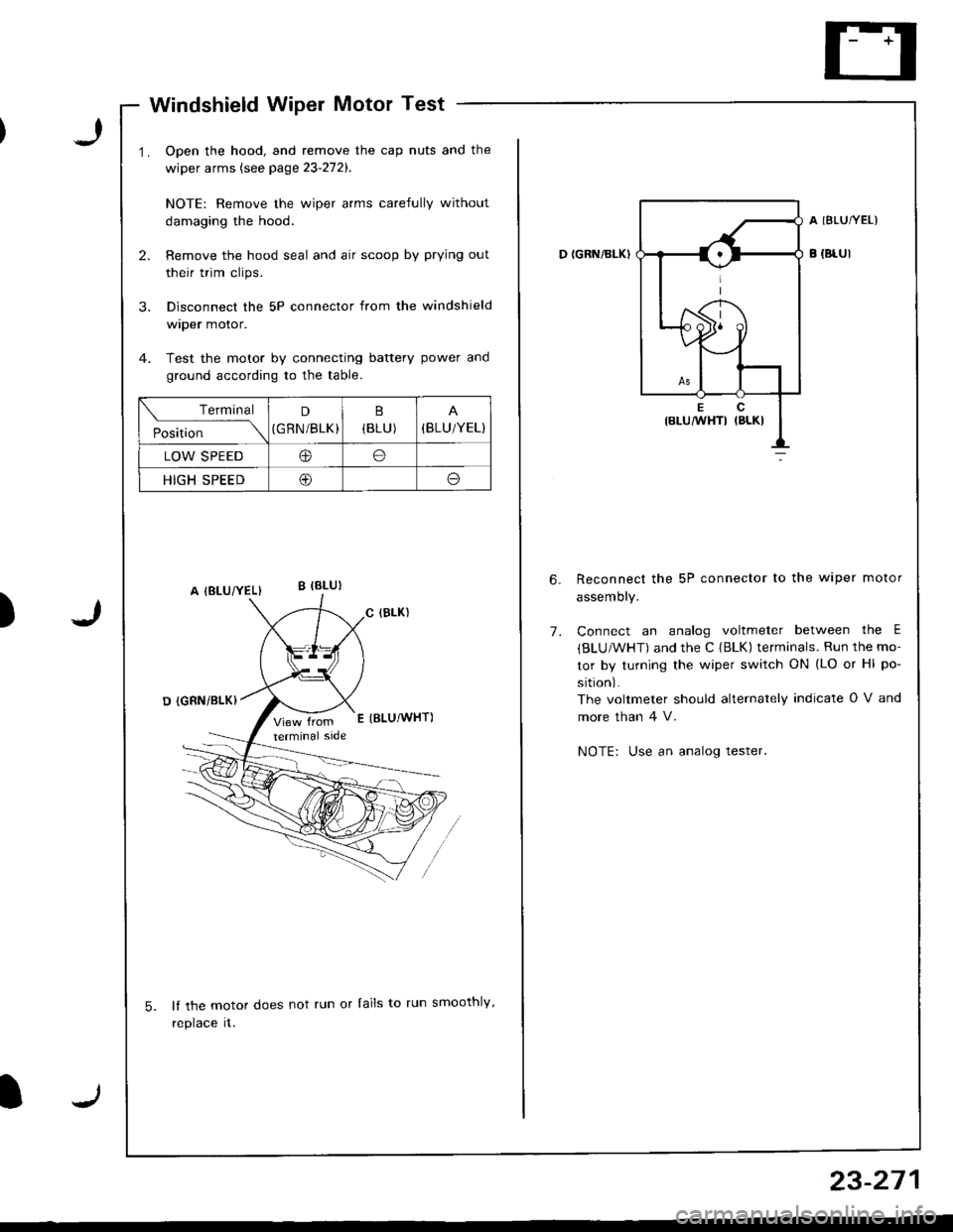
Windshield Wiper Motor Test
Open the hood, and remove the cap nuts and the
wiper arms (see page 23-272).
NOTE: Remove the wiper arms carefully without
damaging the hood.
Remove the hood seal and air scoop by prying out
their trim clips.
Disconnect the 5P connector from the windshield
wtper motor.
Test the motor by connecting battery power and
ground according to the table.
lf the motor does not run or lails to run smoothly,
reptace rr.
)
Terminal
Position
D
(GRN/BLK)(BLU )(BLU/YEL}
LOW SPEEDIto
HIGH SPEED@o
D {GRN/BI-K)
A IBLUTYEL)
B {Br-Ul
7.
Reconnect the 5P connector to the wiper motor
assemory.
Connect an analog voltmeter between the E
{BLU/WHT) and the C {BLK) terminals. Run the mo-
tor by turning the wiper switch ON (LO or Hl po-
sition).
The voltmeter should alternately indicate O V and
more than 4 V.
NOTE: Use an analog tester.
23-271
Page 1327 of 1681
Page 1328 of 1681
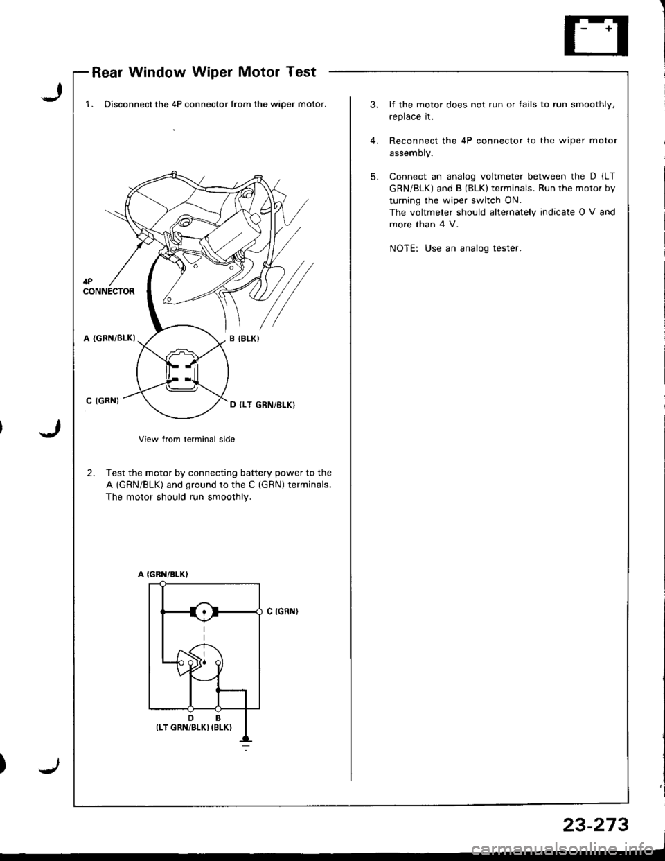
Rear Window Wiper Motor Test
J
J
1 . Disconnect the 4P connector from the wiper motor.3. lf the motor does not run or fails to run smoothly,
replace it.
4. Reconnect the 4P connector to the wiper motor
assemDty.
5. Connect an analog voltmeter between the D (LT
GRN/BLK) and B (BLKI terminals. Run the motor by
turning the wiper switch ON.
The voltmeler should alternately indicate O V and
more than 4 V.
NOTE: Use an analog tester.
1PCONNECTOR
A (GRN/BLKI
C IGRN)
View from terminal side
2. Test the motor by connecting battery power to the
A {GRN/BLK) and ground to the C (GRN) terminals.
The motor should run smoothly.
C IGRN}
);
23-273
Page 1329 of 1681
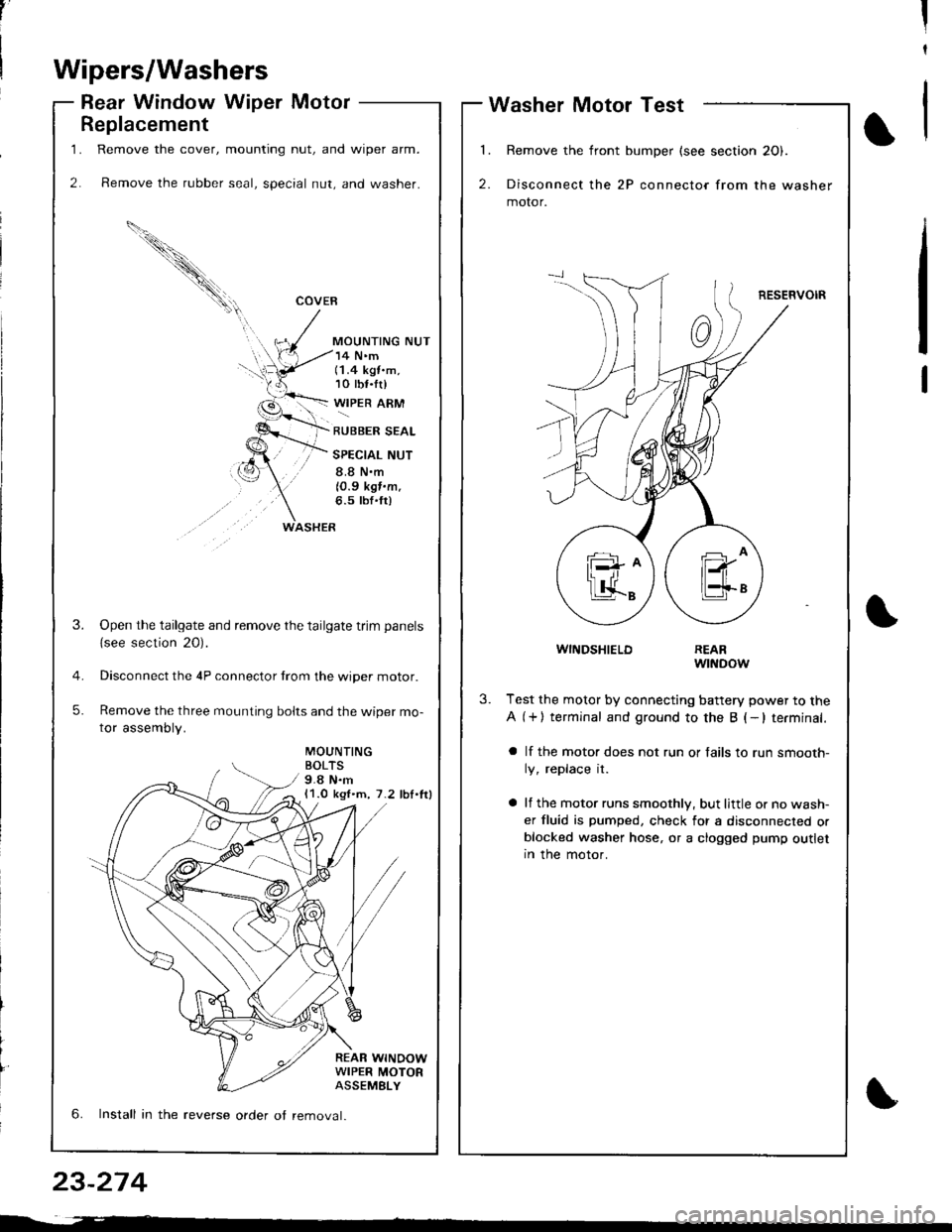
1.
2.
Replacement
Remove the cover, mounting nut, and wiper arm.
Remove the rubber seal, special nut, and washer.
COVEB
MOUNTING NUT
WASHER
14 N'm(1.4 kgt.m,10 tbf.tr)
WIPER ARM
RUBBER SEAL
SPECIAL NUT
8.8 N.m
10.9 kgf.m.6.5 tbf'fr)
MOUNTINGBOLTS9.8 N.m11.0 kgl.m, 7.2 lbl.lrl
REAR WINOOWWIPER MOTORASSEMELY
3.Open the tailgate and remove the tailgate trim panels
{see section 20).
Disconnect the 4P connector trom the wiper motor.
Remove the three mounting bolts and the wiper mo-
tor assembly.
5.
6. Install in the reverse order ot removal.
,'II
t
Wipers/Washers
Rear Window Wiper MotorWasher Motor Test
l�
2.
Remove the front bumper (see section 20).
Disconnect the 2P connector from the washer
motor.
RESERVOIR
1
WINDSHIELDREARwtNDow
3.Test the motor by connecting battery power to the
A (+) terminal and ground to the B (-lterminal.
a lf the motor does not run or fails to run smooth-
ly, replace it.
a lf the motor runs smoothly, but little or no wash-
er fluid is pumped, check for a disconnected orblocked washer hose, or a clogged pump outletIn the motor.
23-274
Page 1330 of 1681
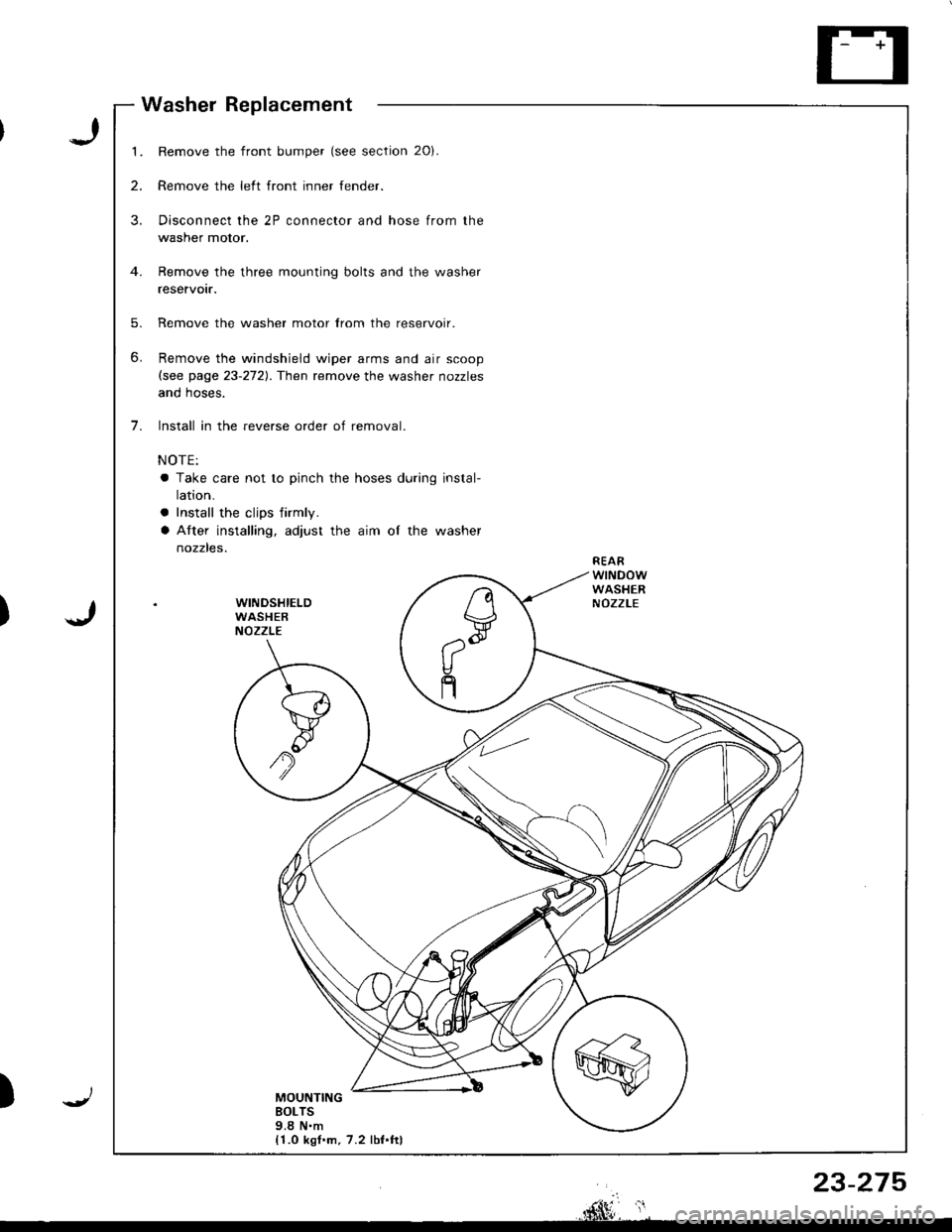
1.
2.
3.
5.
6.
7.
Remove the front bumper (see section 20).
Remove the left front inner fender.
Disconnect the 2P connector and hose from the
washer motor.
Remove the three mounting bolts and the washer
reservotr.
Remove the washer motor lrom the reservoir.
Remove the windshield wiper arms and air scoop(see page 23-272). Then remove the washer nozzles
anq noses.
Install in the reverse order of removal.
NOTE:
a Take care not to pinch the hoses during instal-
ralron.
a Install the cljps firmly.
a After installing, adjust the aim of the washer
nozzles.REAFWINDOWWASHERNOZZLEWINDSHIELDWASHERNOZZLE
MOUNTINGBOLTS9.8 N.m{1.0 kgl.m, 7.2 lbf.ftl
n
V,--"Q
V
n
Washer Replacement
J
J)
)
rnhlF*, ',
23-275
Trending: tire type, fuel cap release, display, oil filter, high beam, c503, oil level
![HONDA INTEGRA 1998 4.G Workshop Manual (
Wipers/Washers
Circuit Diagram
UNDEF.OASHFUSEiRELAYSOX
NTE NMI]TEIIIWPES RELAYCIFCUIT/ In lhe inr6grar6d \ @nlrolun( I
IGNITIONSW TCHUNDER,HOOD FUSE/RELAY BOX
GRI]/BLK
GFIVBLK
WINDSHIELO WPENJWASHE HONDA INTEGRA 1998 4.G Workshop Manual (
Wipers/Washers
Circuit Diagram
UNDEF.OASHFUSEiRELAYSOX
NTE NMI]TEIIIWPES RELAYCIFCUIT/ In lhe inr6grar6d \ @nlrolun( I
IGNITIONSW TCHUNDER,HOOD FUSE/RELAY BOX
GRI]/BLK
GFIVBLK
WINDSHIELO WPENJWASHE](/img/13/6069/w960_6069-1320.png)
