HONDA INTEGRA 1998 4.G Workshop Manual
INTEGRA 1998 4.G
HONDA
HONDA
https://www.carmanualsonline.info/img/13/6069/w960_6069-0.png
HONDA INTEGRA 1998 4.G Workshop Manual
Trending: child restraint, Front bumper, automatic transmission fluid, bulb, washer fluid, Valve cover, check transmission fluid
Page 1301 of 1681
r
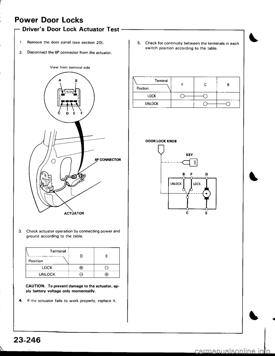
Power Door Locks
Driver's Door Lock Actuator Test
Remove the door panel (see section 20).
Disconnect the 6P connector from the actuator.
CONNECTOR
Check actuator operation by connecting power and
ground according to the table.
CAUTION: To prevent damage to the acluator, ap-ply battely voltage only momentarily.
if the actuator fails to work properly, replace it.
Terminal
DE
Position
LOCK@o
UNLOCKo@
5. Check for continuity between the terminals in each
switch position accordiog to the table.
DOOR LOCK KNOB
Terminal
il;;-----tFcB
LOCKoo
UNLOCKo-----o
23-246
Page 1302 of 1681
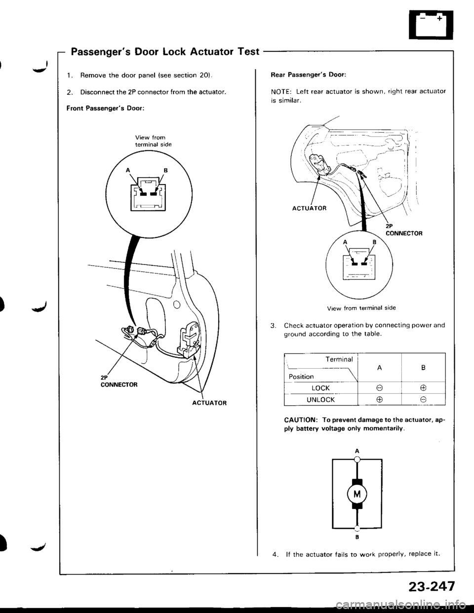
Passenger's Door Lock Actuator Test
1. Remove the door panel (see section 20).
2. Disconnect the 2P connector from the actuator.
Front Passenger's Door:
lerminal side
ACTUATOR
)J
23-247
Rear Passenger's Door:
NOTE: Left rear actuator is shown, right rear actuator
is similar.
View from lerminal side
Check actuator operation by connecting power and
ground according to the table.
CAUTION: To prevent damage to the actuator, ap-
ply battery voltage only momenta.ily.
;
4. lf the actuator tails to work properly, replace it.
Term inal
Position
B
LOCKo@
UNLOCKoo
Page 1303 of 1681
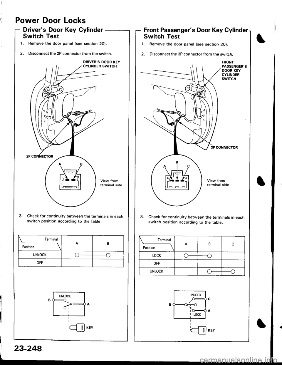
Power Door Locks
Driver's Door Key Cylinder
Switch Test
1. Remove the door panel (see section 20).
2. Disconnect the 2P connector f.om the switch.
terminal side
Check tor continuity between the terminals in eachswitch position according to the table.
Front Passenger's Door Key Cylinder
Switch Test
1. Remove the door panel (see section 20).
2. Disconnect the 3P connector from the switch.
FRONTPASSENGER'SDOOR KEYCYLINDERSwlTCH
CONNECTOR
3. Check for continuity between the terminals in eachswitch position according to the table.
Terminal
il;------__\tt
UNLOCKoo
OFF
Terminal
P**--__\c
LOCKo--o
UNLOCKoo
UNTOCK<
I
UNLOCK
r--O\:
I LOCK
23-248
(--l__!J KEYtil
Page 1304 of 1681
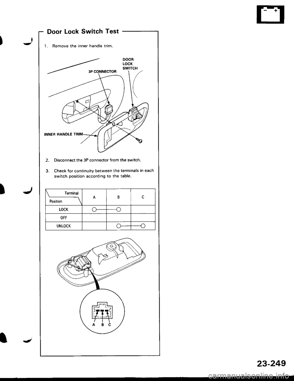
Door Lock Switch Test
1. Remove the inner handle trim.
2. Disconnect the 3P connector from the switch.
3. Check tor continuity between the terminals in each
switch position according to the table.
)
oooRLOCKswtTcH
Terminal
t"r--
-\Bc
LOCKo-----o
OFF
UNLOCKoo
4
23-249
Page 1305 of 1681
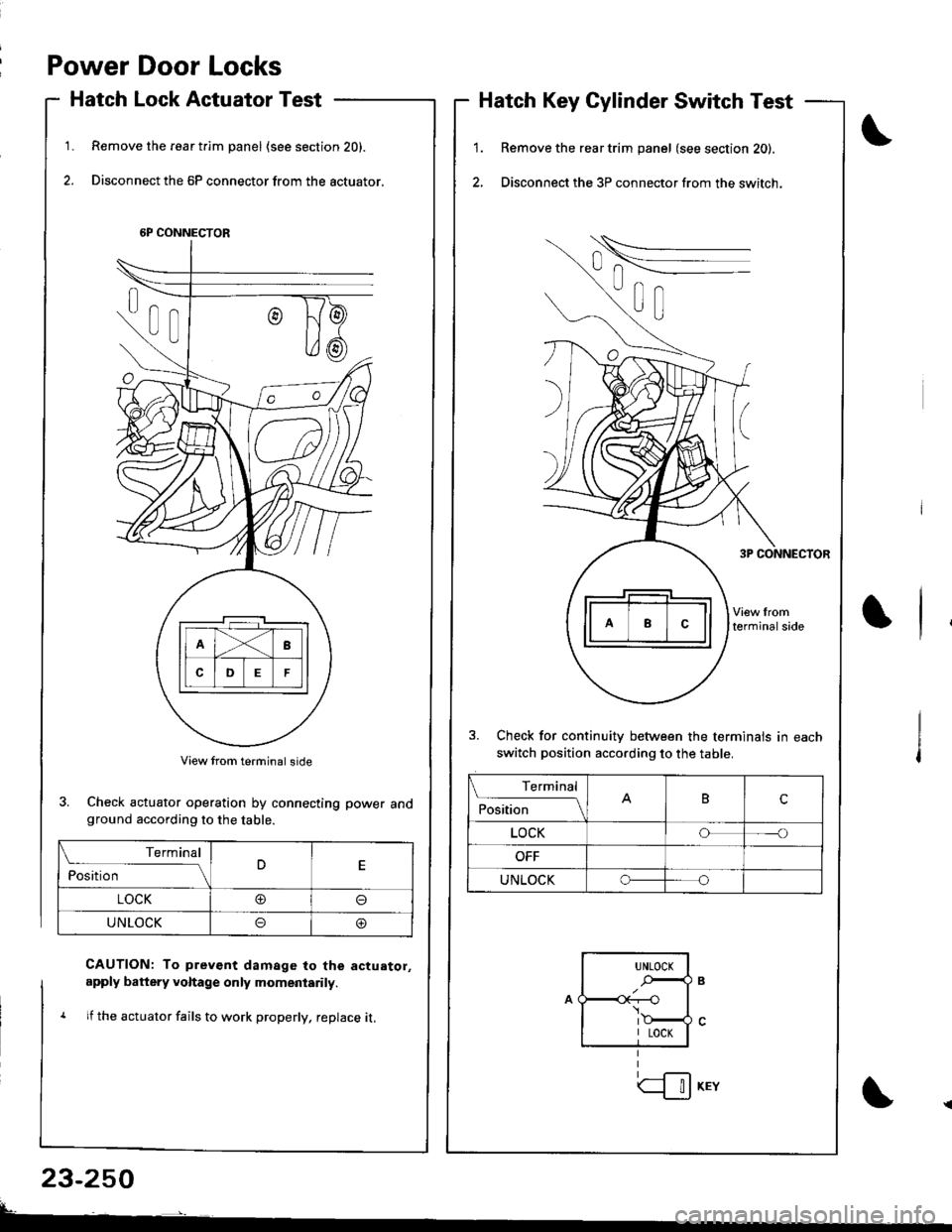
Power Door Locks
Hatch Lock Actuator Test
Remove the rear t.im panel (see section 20).
Disconnect the 6P connector from the actuator.
1.1.
2.
Hatch Key Cylinder Switch Test
Remove the rear trim panel (see section 20).
Disconnect the 3P connector from the switch.
3. Check for continuitv between the terminals in each
switch position according to the table.
6P CONNECTOR
3. Check actuator operation by connecting power andground according to the table.
CAUTION: To prev€nt damage to the actuator,
apply battery voltage only momeniarily.
1 lf the actuator fails to work properly, replace it,
23-250
Terminal
ilil;---tBc
LOCKoo
UNLOCKo
Terminal
ilil;-]E
LOCK@o
UNLOCKoo
UNLOCK
.-,4
I LOCK
| !J KEY
Page 1306 of 1681
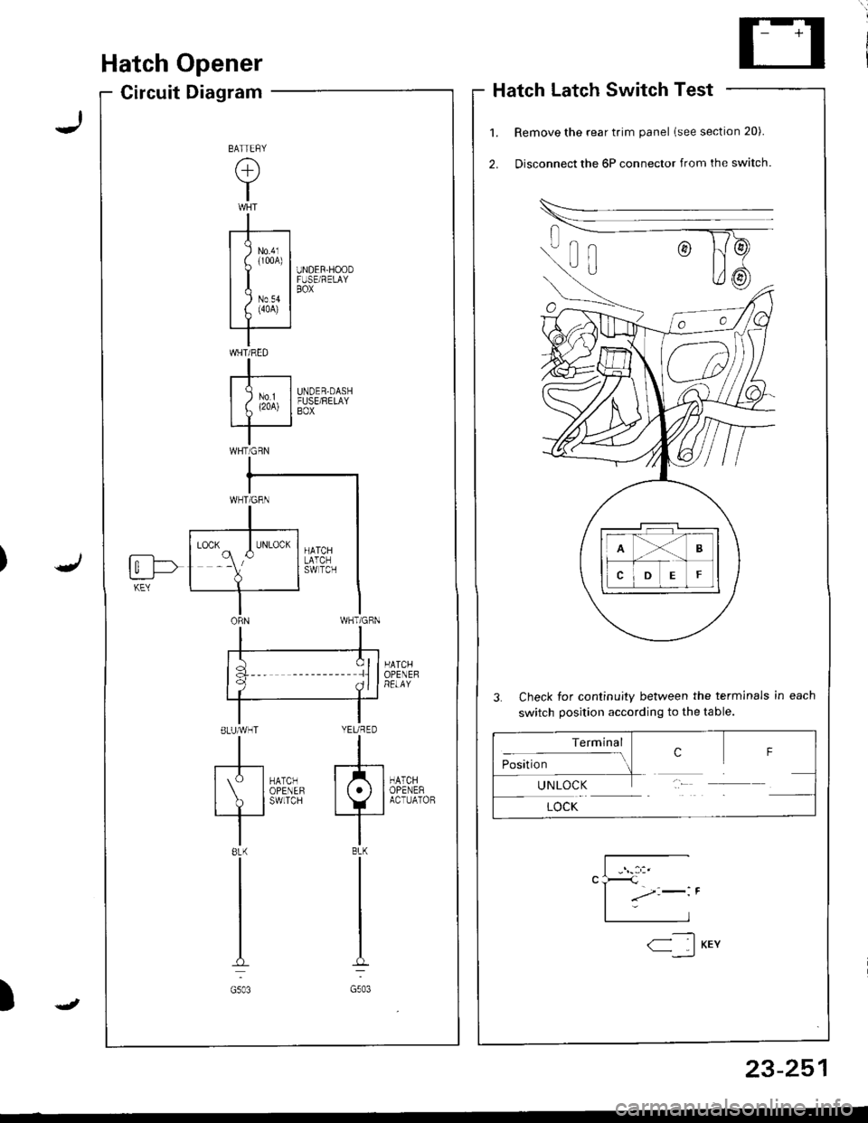
Hatch Opener
Circuit DiagramHatch Latch Switch Test
Remove the rear trim panel lsee section 20).
Disconnect the 6P connector from the switch.
3. Check for continuity between the terminals in each
switch position according to the table.
HATCHOPENEHRELAY
HATCHOPENERACTUATOB
UNDER-HOODFUSE/RELAYBOX
UNDER.DASHFUSE/RELAYBOX
la :llf q ^ll
ELUMHT YEURED
tl
[S-l*0,., f/tl| IoPENEF lt.l I
I ? l'*n'" +_i
tl8LK BLK
tl
tl
tt.:
G503 G503
BATTEFY
(+)
Y
I
-r--t
I I lm,1
uI| )Nov II f. (4oA) |rT '
IWHT/RED
I-r----| )ur II L (2oA) I
IWHTiGRN
fi--l->t_:___J-KEY
Terminal
:- ..- crosrUon-1UNLOCK
LOCK
F
23-251
-----t1< IKEY--,_)
J
Page 1307 of 1681
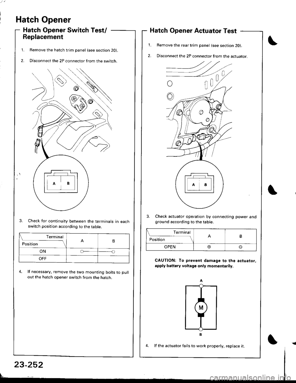
Hatch Opener
Hatch Opener Switch Test/
Replacement
Remove the hatch trim panel (see section 20).
Disconnect the 2P connector from the switch.
3. Check for continuity between the terminals in eachswatch position according to the table.
4. lf necessary, remove the two mounting bolts to pull
out the hatch opener switch from the hatch.
1.
2.
1.
2.
Hatch Opener Actuator Test
Remove the rear trim panel (see section 20).
Disconnect the 2P connector from the actuator.
3. Check actuator operation by connecting power andground according to the table.
CAUTION: To prevent damage to the actuator,
apply battery voltage only momentarily.
Terminal
PositionB
ONo
OFF
Terminal
PositionB
OPEN@o
23-252
4. lf the actuator fails to work properly, replace it.{
Page 1308 of 1681
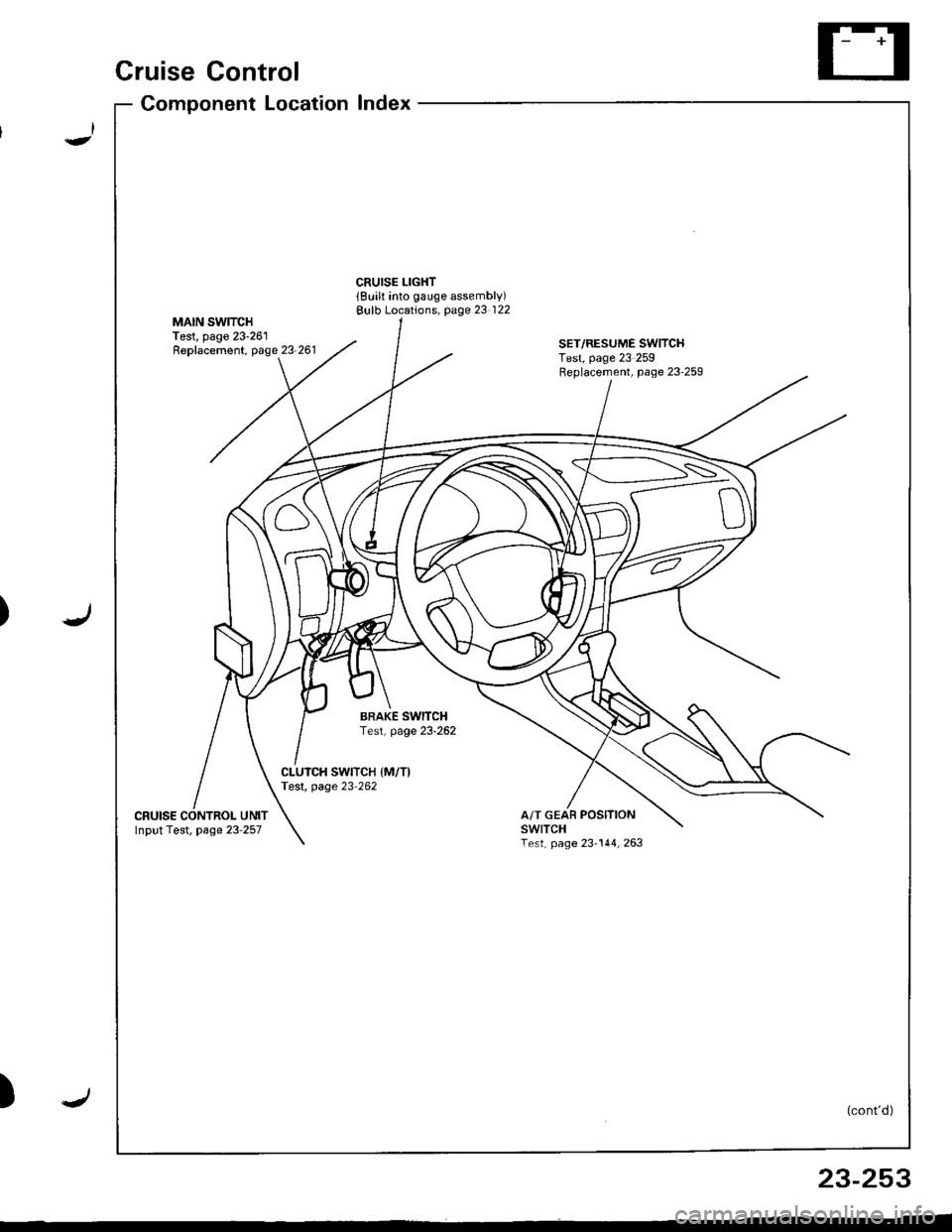
Cruise Control
)
Component LocationIndex
CRUISE LIGHT{Built into gauge assembly)Bulb Locations, page 23 122MAIN SWITCHTest, page 23-261Replacement, page 23-261SET/RESUME SWITCHTest, page 23 259Feplacement, page 23'259
BRAKE SwlTCHTest, page 23-262
CLUICH SWITCH IM/T)Test, page 23 262
cRutsEA/T GEAR POSITIONswtTcHTest, page 23-144,263Input Test, page 23 257
(cont'd)
23-253
Page 1309 of 1681
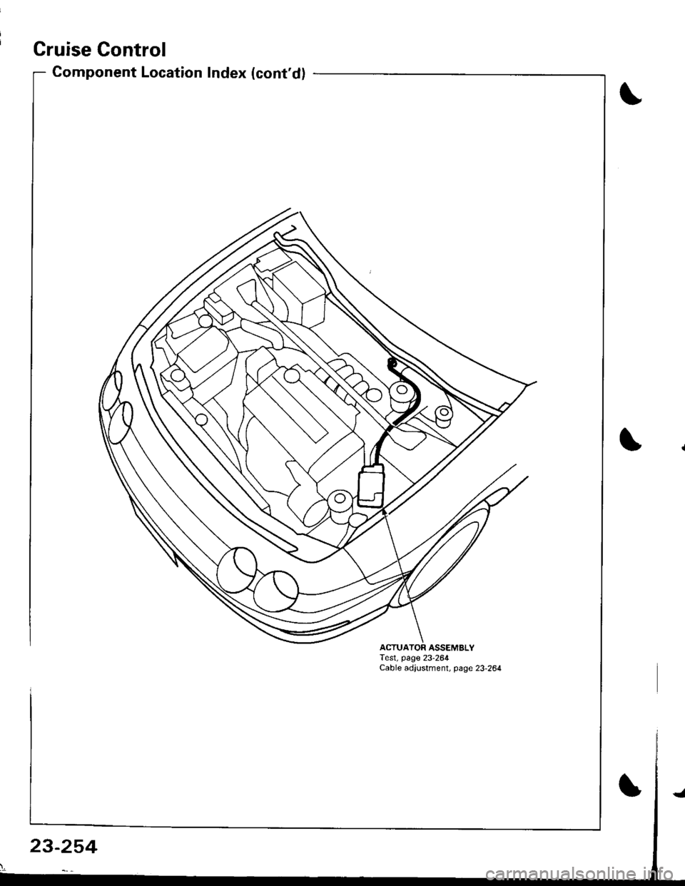
Cruise Control
Component Location Index (cont'd)
ACTUATOR ASSEMBLYTest, page 23-264Cable adjustment, page 23-264
23-254
Page 1310 of 1681
Circuit Diagram
J
WNT/BLK +WHT
BLKYEL YEL/8LU
CABLEREEL
SET/BESUME1 SW]TCH
J
IGNITONCONTROLMODULE(cM)
LT
B lA
i,"'YlDGBY
c
IT GRN/RED LTGRN/BLK
BLK
I
:
:2013401
III
I
VEHICLE SPEEDSENSOR (VSS)
M/T: CLLTCH SWITCH \A/T:A,TGEARPostT oN swrc!(oN E].tr tr
8LK 8LK
lltl-0-_L-- --
G301 G2AlG401
UNDER-HOOD FUSEiFELAY BOXUNDEF DASH FUSEi RELAY BOX
lNDICATORL]GHT(0.91W)
BLU/RED
23-255
:?:'
ACC : ACCELERATIONOEC iDECELERATION
Trending: warning, oil viscosity, transmission oil, c503, radio, oil dipstick, bulb
![HONDA INTEGRA 1998 4.G Workshop Manual Circuit Diagram
J
WNT/BLK +WHT
BLKYEL YEL/8LU
CABLEREEL
SET/BESUME1 SW]TCH
J
IGNITONCONTROLMODULE(cM)
LT
B lA
i,"YlDGBY
c
IT GRN/RED LTGRN/BLK
BLK
I
:
:2013401
III
I
VEHICLE SPEEDSENSOR (VSS)
M/T: CL HONDA INTEGRA 1998 4.G Workshop Manual Circuit Diagram
J
WNT/BLK +WHT
BLKYEL YEL/8LU
CABLEREEL
SET/BESUME1 SW]TCH
J
IGNITONCONTROLMODULE(cM)
LT
B lA
i,"YlDGBY
c
IT GRN/RED LTGRN/BLK
BLK
I
:
:2013401
III
I
VEHICLE SPEEDSENSOR (VSS)
M/T: CL](/img/13/6069/w960_6069-1309.png)