HONDA INTEGRA 1998 4.G Workshop Manual
Manufacturer: HONDA, Model Year: 1998, Model line: INTEGRA, Model: HONDA INTEGRA 1998 4.GPages: 1681, PDF Size: 54.22 MB
Page 1291 of 1681
Power
Master
Windows
Switch Input Test (Hatchbackl
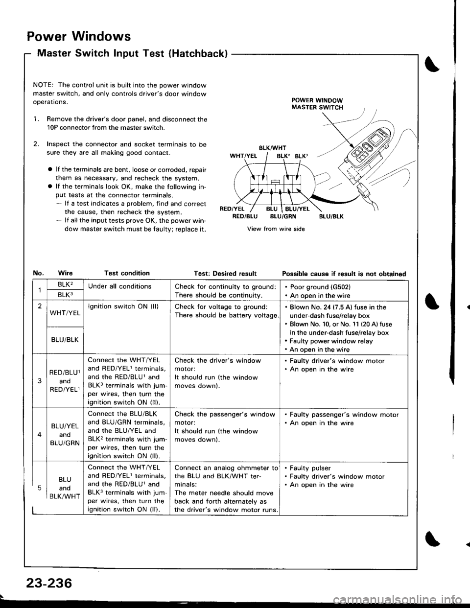
NOTE: The control unit is built into the power window
master switch, and only controls driver's door window
ooerations.POWER WINDOWMASTER SWITCH
1.Remove the driver's door panel, and disconnect the
10P connectorfrom the master switcn.
Inspect the connector and socket terminals to be
sure they are all making good contact.
a lI the terminals are bent, loose or corroded, reDair
them as necessary, and recheck the system.
a lf the terminals look OK, make the following in-
put tests at the connector terminals.- It a test indicates a problem, find and correct
the cause, then recheck the system.- lf all the input tests prove OK, the power win-
dow master switch must be taulty; reDlace it.
No.WileTest condition
BLK/WHT
BLK' BLKI
RED/YELRED/BLUBLU/GRNBLU/BLK
View from wire side
Tgst: DesiredresultPossibls cause if result is not obtainsd
BLU
and
BLK/WHT
Check for continuity to ground:
There should be continuity.
Poor ground (G502)
An open in the wire
lgnition switch ON (ll)Check for voltage to ground:
There should be battery voltage
. Blown No. 24 (7.5 A) fuse in the
under-dash fuse/relay box' Blown No. 10, or No. '11 (20 A) fuse
in the under-dash fuse/relay box. Faulty power window relay. An open in the wire
Connect the WHT/YEL
and RED/YELI terminals,
and the RED/BLU1 and
BLK3 terminals with jum-
per wires, then turn the
ignition switch ON (ll).
Check the driver's window
motor:
It should run (the window
moves oownl.
. Faulty driver's window motor. An open in the wire
Connect the BLU/BLK
and BLU/GRN terminals,
and the BLU/YEL and
BLK2 terminals wjth jum-
per wires, then turn the
ignition switch ON (ll).
Check the passenger's window
motor:
It should run (the window
moves oownl.
. Faulty passenger's window motor. An open jn the wire
Connect the WHT/YEL
and RED/YEL1 terminals.
and the RED/BLUI and
BLK3 terminals with jum-
per wires, then turn the
ignition swirch ON (ll).
Connect an analog ohmmeter to
the BLU and BLK/WHT ter-
minals:
The meter needle should move
back and forth alternately as
the driver's window motor runs.
. Faulty pulser. Faulty driver's window motor. An open in the wire
23-236
Page 1292 of 1681
Master Switch Test (Sedanl
't
J)
I
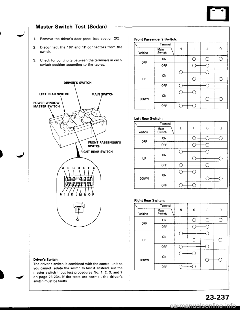
1.Remove the driver's door panel (see section 20).
Disconnect the 16P and 1P connectors from the
switch.
Check Jor continuity between the terminals in each
switch position according to the tables.
,,
s swtTcH
LEFT REAF SWITCHMAIN SWITCH
POWER WINDOWMASTER SWITCH
PASSENGER'SswtTcH
RIGHT REAR SWITCH
Drivsr's Switch:
The driver's switch is combined with the control unit so
vou cannot isolate the switch to test it. Instead, run the
master switch input test procedures No. 1, 2, 3. and 7
on page 23-234. lf the tests are normal, the driver's
switch must be faulty.
Front Passenger's Swltch:
Terminal
JoI uain \Position I Switch \
OFFONG_o--o
OFFG*--o
UPONo---o
o-
OFFo---o
DOWNONo---o
G-_O
OFFG--o
ABCDEFG
HIJKLMNO
L€ft Rear Switch:
Terminal
EFGoI Main \Position I Switch \
OFFONo-o--o
OFFo---o
UPONo---o
--oo-
OFFo---o
DOWNONo---o
o--o
OFFo--o
Right Rear Switch:
Terminal
ooPosirion | 35ii.r \
OFFONG-
OFFo-._,f
UPON.)-]--------{-)1___i----o
OFFo--o
DOWNONc-l
o-
oFF :----o
J
23-237
Page 1293 of 1681
Power Windows
Master Switch Test (Hatchback)Passenger's Window Switch Test
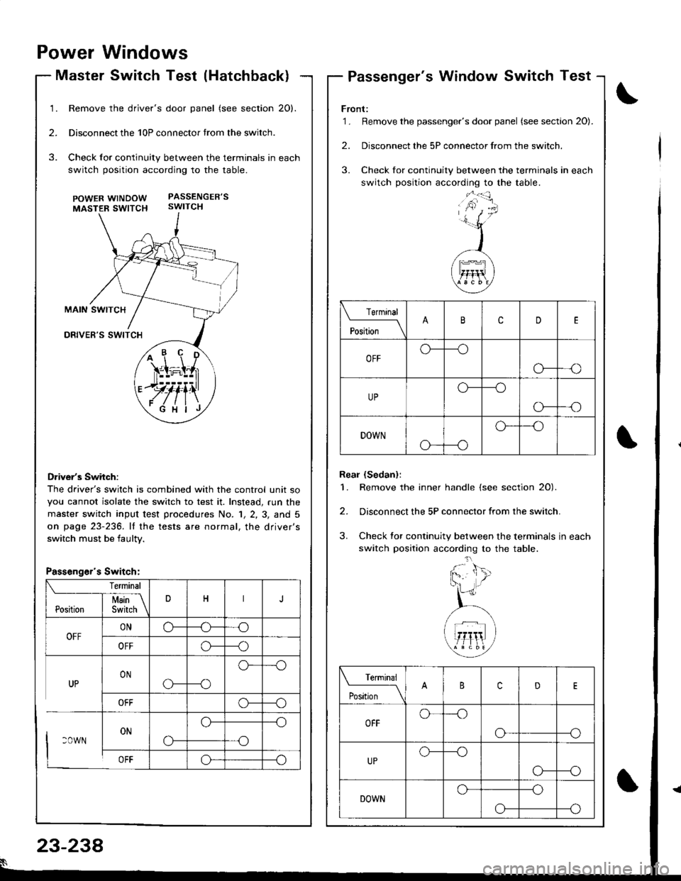
Remove the driver's door panel (see section 20).
Disconnect the 10P connector trom the switch.
Check for continuity between the terminals in each
switch position according to the table.
POWERwtNDOW PASSENGER'S
MASTER SWTTCH swtTCH
Driver's Switch:
The driver's switch is combined with the control unit so
you cannot isolate the switch to test it. Instead, run the
master switch input test p.ocedures No. 1, 2, 3, and 5
on page 23-236. lf the tests are normal, the driver's
switch must be iaultv.
/+ r' \'ir=i;l,r
.JJ#iill
ryfi'\
Front:'1. Remove the passenger's door panel (see sectaon 20).
2. Disconnect the 5P connector from the switch.
3. Check for continuity between the terminals in each
switch position according to the table.
Real (Sedan):
1. Remove the inner handle (see section 20).
2. Disconnect the 5P connector from the switch.
3. Check tor continuity between the terminals in each
switch position according to the table.
Terminal
'*';__\cD
OFFo---o
o---o
UPo---o
o-
DOWN
o---o
o--'o
Terminal
t"t-* \cD
OFFo---o
o---o
UPo--_o
o---o
DOWNo---o
--oo-
Passenger's Switch:
23-238
Page 1294 of 1681
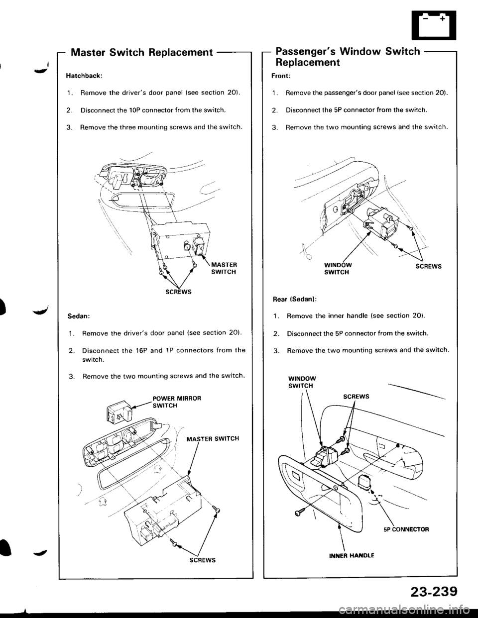
Hatchback:
1. Remove the driver's door panel (see section 20).
2. Disconnecl the 10P connector from the switch.
3. Remove the three mounting screws and the switch.
Sedan:
1. Remove the driver's door panel (see section 20).
2. Disconnect the 16P and 1P connectors from the
swrtcn.
3. Remove the two mounting screws and the switch.
POWER MIRRORswtrcH
scBEws
Master Switch ReplacementPassenger's Window Switch
I-
.J)
I
Replacement
Front:
1 . Remove the passenger's door panel lsee section 20).
2. Disconnect the 5P connector from the switch.
3. Remove the two mounting screws and the switch.
Rear (Sedan);
1. Remove the inner handle (see section 2O).
2. Disconnect the 5P connector from the switch.
3. Remove the two mounting screws and the switch.
wtNDowswrTcH
swtTcH
5P CONNECTOR
IN ER HATOLE
23-239
Page 1295 of 1681
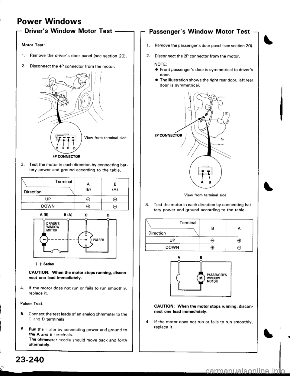
Power Windows
Driver's Window Motor Test
Motor Test:
'1. Remove the driver's door panel (see section 20).
2. Disconnect the 4P connector from the motor.
View from terminal side
4P CONNECTOR
3. Test the motor in each direction by connecting bat-tery power and g.ound according to the table.
CAUTION: When the motor stops running, discon-
nect one lead immediately.
4. lf the motor does not run or fails to run smoothly.
reprace rI.
Pulser Test:
5. Connect the test leads of an analog ohmmeter to the: and D terminals.
6. Run the -noror by connecting power and ground totho A anO 8:errninals.
Thg ohmrneter need e should move back and forthalternately,
1.
2.
Passenger's Window Motor Test
Remove the passenger's door panel {see section 20).
Disconnect the 2P connector from the motor.
NOTE:
a Front passenger's door is symmetricalto driver's
door.
a The illustration shows the right rear door. left rear
door is symmetrical.
2P CONNECTOR
View from terminal side
3. Test the motor in each direction by connecting bat-
tery power and ground according to the table.
CAUTION: When the motol stops running, discon-
nect one lead immediately.
lf the motor does not run or fails to run smoothlv,
reprace rI.
(
I
Terminal
Direction{B)
B
{At
UPo@
DOWN@o
Terminal
O'*"r*-TB
UPo@
DOWN@o
23-240
Page 1296 of 1681
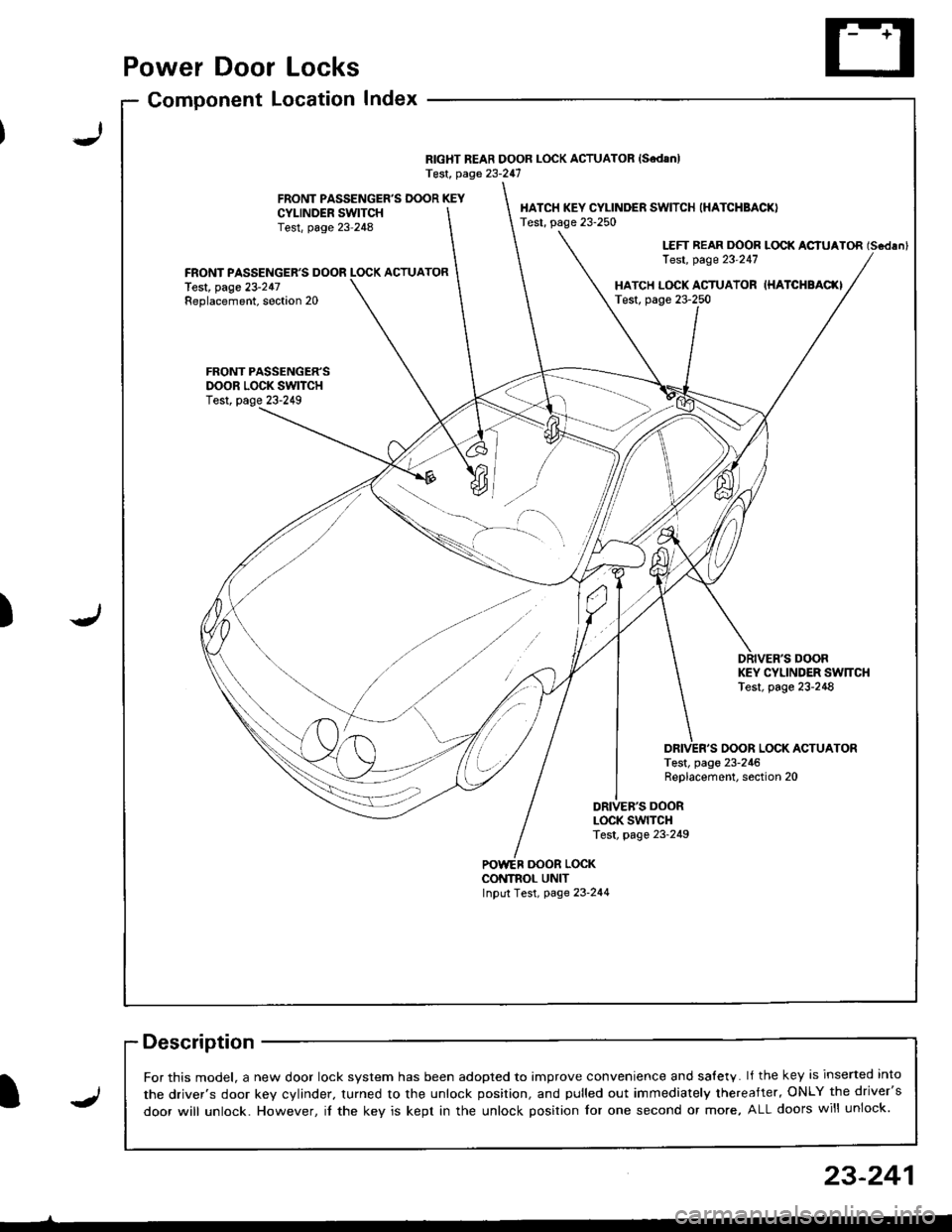
Power Door Locks
Component LocationIndex
RIGHT REAR DOOR LOCK ACTUATOR {SedanlTest, page 23-247
FRONT PASSENGER'S DOOR KEYCYI-INDER SWITCHTest, page 23-248
HATCH KEY CYLINDER SWITCH (HATCHBACK)
Test, page 23-250
LEFT REAR DOOR LOCK ACIUATOR (Scdlnl
Test, page 23'247FRONT PASSENGER'S DOOR LOCK ACTUATORlest, page 23-247Replacement, soction 20HATCH L(rcK ACTUATOR IHATCHBAC(ITest, page 23-250
FRONT PASSENGER'SDOOR LOCK SWITCHTest, page 23-249
DRIVER'S DOORKEY CYLINDER SW]TCHTest, page 23-248
OOOR LOCK ACTUATORTest, page 23-246Replacement, section 20
DRIVEB'S DOORLOCK SWITCHTest, page 23-249
oooR LocKCONTNOL UNITInput Test, page 23-244
-)
J)
I
For this model, a new door lock svstem has been adooted to imDrove convenience and salety. lf the key is inserted into
the driver's door kev cvlinder. turned to the unlock position, and pulled out immediately thereafter, ONLY the driver's
door will unlock. However, il the key is kept in the unlock position for one second or more, ALL doors will unlock.J
23-241
Page 1297 of 1681
![HONDA INTEGRA 1998 4.G Workshop Manual Power Door Locks
Circuit Diagram
@*"
DR]VERS000R LocKSWITCH
NATCN KEYCYLINDER SWITCH
L_____
ooon rocx xroe If7 l
VIKEY
DRIVERSDOOR LOCKACTUATOR
E
UNDER.HOOO FUSEi RELAY BOX
N0.41 (1004) No.s4 (40A)
HONDA INTEGRA 1998 4.G Workshop Manual Power Door Locks
Circuit Diagram
@*"
DR]VERS000R LocKSWITCH
NATCN KEYCYLINDER SWITCH
L_____
ooon rocx xroe If7 l
VIKEY
DRIVERSDOOR LOCKACTUATOR
E
UNDER.HOOO FUSEi RELAY BOX
N0.41 (1004) No.s4 (40A)](/img/13/6069/w960_6069-1296.png)
Power Door Locks
Circuit Diagram
@*"
DR]VER'S000R LocKSWITCH
NATCN KEYCYLINDER SWITCH
L_____
ooon rocx xroe If7 l
VIKEY
DRIVER'SDOOR LOCKACTUATOR
E
UNDER.HOOO FUSEi RELAY BOX
N0.41 (1004) No.s4 (40A)
DFIVERS DOORKEY CYLJNOERSWITCH
WHT/GRN
FRONTPASSENGERSDOOR LOCKACTUATOR
T--=-l-4{il^
* LEFT REARDOOR LOCKACTUATOR
,@-
* RIGHT NEARDOOR LOCKACTUATOH
-4{.ill^
HATCH LOCKACTUATOR
T-:-lfl.|.{-
LTGRN
LT BLU
A
t--lt=JKEY
i
Atl
T-tl-lKEYBLK
I
G503
.LK BLKll
tlAA
:-l
G501 G2r.G502 ercl
BLK
,l'
G5o1G502
LOCK
o
POWER DOORLOCK CONTROLUNIT
8LK
A-l
G501G502
23-242
Page 1298 of 1681
I,t
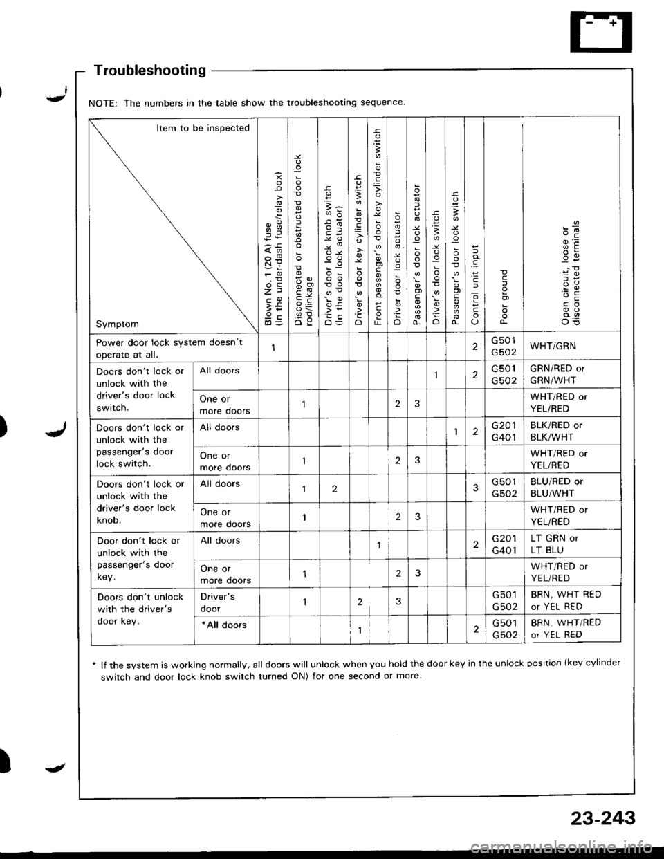
Troubleshooting
* lf the system is working normally, all doors will unlock when you hold the door key in the unlock oosrtion {key cylinder
switch and door lock knob switch turned ON) for one second or more
)
NOTE: The numbers in the table show the troubleshooting sequence
Item to be inspected
Symptom
g
;i
:
5
{,!
(,o
o-c
E5
B
'io
B
o)c
c
o
:
D
.uo
I
o)
o-
-c
:o
o
I
!
o)
cJ
o
c
c
o)
Power door lock system doesn't
operate at all.
G501
G502WHT/GRN
Doors don't lock or
unlock with the
driver's door lock
switch.
All doors2G 501
G502
GRN/RED or
GRN/WHT
One or
more doors
'I23WHT/RED or
YEL/RED
Doors don't lock or
unlock with the
passenger's door
lock switch.
All doors1G201
G401
BLK/RED or
BLK/WHT
One or
more ooors123WHT/RED or
YEL/RED
Doors don't lock or
unlock with the
driver's door lock
knob.
All doors123G501
G502
BLU/RED or
BLU/WHT
One or
more doors123WHT/RED or
YEL/RED
Door don't lock or
unlock with the
passenger's door
key.
All doorsl2G201
G401
LT GRN or
LT BLU
One or
more doors2WHT/RED or
YEL/RED
Doors don't unlock
with the driver's
door key.
Driver's
ooor23G501
G502
BRN, WHT REO
or YEL RED
*All doors1G 501
G502
BRN, WHT/RED
or YEL RED
-
23-243
Page 1299 of 1681
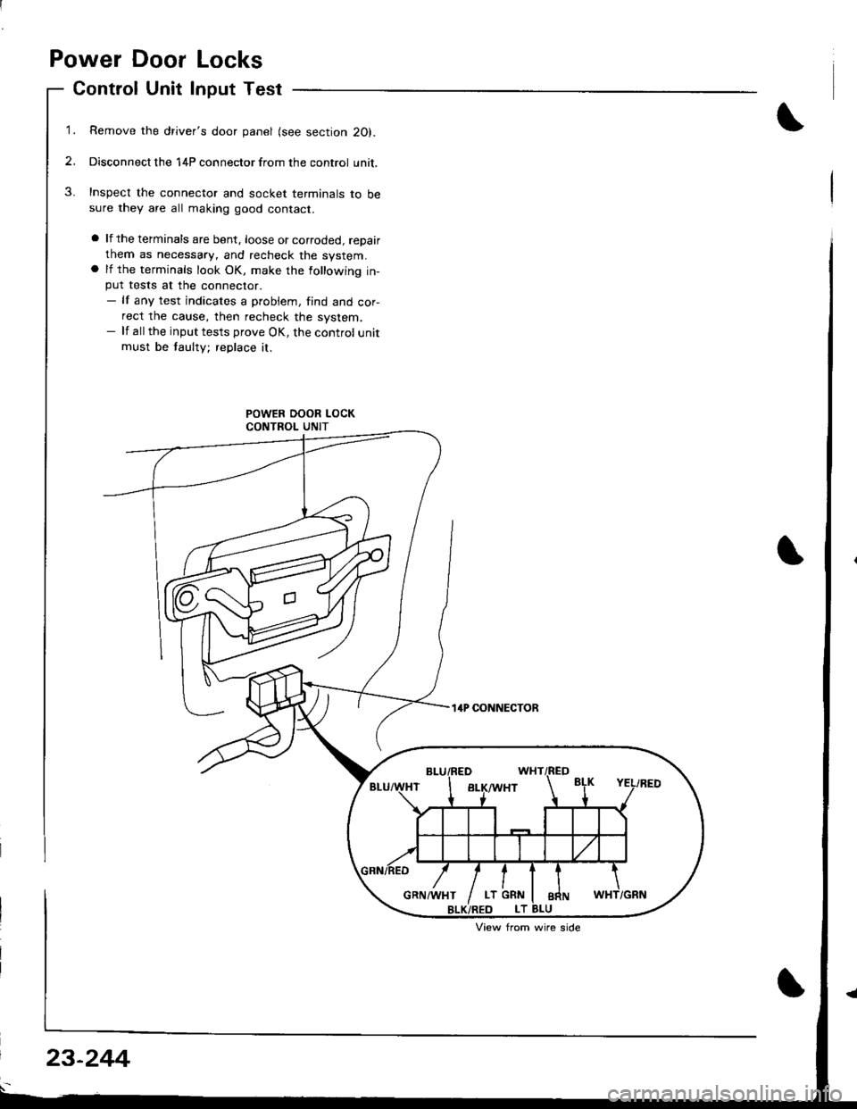
Power Door Locks
Control Unit Input Test
1.Remove the driver's door panel (see section 20).
Disconnect the 14P connector from the control unit,
Inspect the connector and socket terminals to besure they are all making good contact.
a lf the terminals are bent. loose or corroded, repairthem as necessary, and recheck the system.a lf the terminals look OK, make the following in-put tests at the connector.- lf any test indicates a probiem, find and cor-rect the cause, then recheck the system.- lf all the input tests prove OK, the control unitmust be faulty; replace it.
14P CONNECTOR
View from wire side
23-244
Page 1300 of 1681
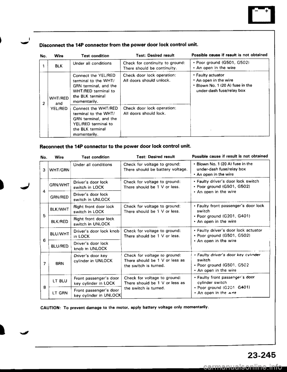
Disconnect the 14P connector from the power door lock control unit'
)
No. WileTest conditionTest: Dgsired resultPossible causo if rosult is not obtained
Reconnect the 14P conneetor to the power door lock control unit'
No. wireTest conditionTest: Desired resultPossible cause il result is not obtained
I
1BLKUnder all conditionsCheck tor continuity to ground:
There should be continuity.
. Poor ground (G50'1, G502). An open in the wire
2
WHTi RED
ano
YEL/RED
connect the YEL/RED
terminal to the WHT/
GBN terminal, and the
WHT/RED terminal to
the BLK terminal
momentarily.
Check door lock operation:
All doors should unlock.
Faulty actuator
An open in the wire
Blown No. 1 {20 A} fuse in the
under-dash Juse/relay box
Connect the WHT/RED
terminal to the WHT/
GRN terminal, and the
YEL/RED terminal to
the BLK terminal
momentanly.
Check door lock operation:
All doors should lock.
3WHT/GRN
Under all conditionsCheck for voltage to ground:
There should be battery voltage.
. Blown No. 1 (20 A) fuse in the
under-dash fuse/relay box. An open in the wire
GRN/WHTDriver's door lock
switch in LOCK
Check lor voltage to ground:
There should be 1 V or less.
Faulty driver's door lock switch
Poor ground (G501, G502)
An open in the wire
GRN/REDDriver's door lock
switch in UNLOCK
5
BLK/WHTRight front door lock
switch in LOCK
Check for voltage to ground:
There should be 1 V or less.
Faulty front passenger's door lock
switch
Poor ground (G201 , G401)
An open in the wireBLKi REDRight front door lock
switch in UNLOCK
BLU/WHTDriver's door lock knob
in LOCK
Check for voltage to ground:
There should be 1 V or less.
. Faulty driver's door lock actuator. Poor ground (G501, G502). An open in the wire
BLU/REDDriver's door lock
knob in UNLOCK
7BRN
Oriver's doo. key
cylinder in UNLOCK
Check for voltage to ground:
There should be 1 V or less as
the switch is turned.
. Faulty driver's door key cvtrrder
switch. Poor ground (G501, G502. An open in the wire
8
LT BLUFront passenger's door
key cylinder in LOCK
Check for voltage to ground:
There should be 1 V or less as
the switch is turned.
. Faulty front passengef's door
cylinder switch. poor ground lG20r G4Ol). An open in the *reLT GRNFront passenger's door
key cylinder in UNLOCK
\J
CAUTION: To prevent damage to the motol, apply battery voltage only momentarily
23-245