ignition HONDA INTEGRA 1998 4.G Workshop Manual
[x] Cancel search | Manufacturer: HONDA, Model Year: 1998, Model line: INTEGRA, Model: HONDA INTEGRA 1998 4.GPages: 1681, PDF Size: 54.22 MB
Page 1033 of 1681
![HONDA INTEGRA 1998 4.G Workshop Manual COMPRESSOR CLUTCH RELAY P SOCIGT
I
,l
I
i:]
lll
i
ll
rl.
,i
lil
ECM CONNECTOR A (32PI
BLK/f,ED
WIRE SIDE OF FEMALE TERMINALS
ECM CONNECTOR C {31P}
BLU/RED
Connect the backprobe adapters to the stacki HONDA INTEGRA 1998 4.G Workshop Manual COMPRESSOR CLUTCH RELAY P SOCIGT
I
,l
I
i:]
lll
i
ll
rl.
,i
lil
ECM CONNECTOR A (32PI
BLK/f,ED
WIRE SIDE OF FEMALE TERMINALS
ECM CONNECTOR C {31P}
BLU/RED
Connect the backprobe adapters to the stacki](/img/13/6069/w960_6069-1032.png)
COMPRESSOR CLUTCH RELAY 'P SOCIGT
I
,l
I
i:]
lll
i
ll
rl.
,i
lil
ECM CONNECTOR A (32PI
BLK/f,ED
WIRE SIDE OF FEMALE TERMINALS
ECM CONNECTOR C {31P}
BLU/RED
Connect the backprobe adapters to the stacking patch cords, and connect the cords to a mul-timeter. Using the wire insulation as a guide lor the contoured tip oI the backprobe adapter,gently slide the tip into the connector trom the wire side until it comes in contact with the ter-minalend ofthe wire {see section l1).
From page 22-14
*How to use the backprobe sets
Turn the ignition switch ON {11}.
i/leasure the voltage between theNo. 4 wire terminal (+) and bodyground {-).
Rcp.ir opon in tho BLK/YEL wirobetwsen tha undor.dash tu3a/rehy box rnd the undor.hoodfw6/i6lry box.
Turn tho ignition switch OFF, andreinstall the compressor clutch
Make suro the !y'C and heater fanswitches are OFF.
Turn the ignition switch ON {l1).
Using a *Backprobe Set (T/N
07SAZ - 001000A), measure th€voltage between the No. 17 termi-nal oI the ECM connocror A (32P)
and body ground wirh the ECMconnectors connected.
R.pair op.n in tho BLK/R€O wirobgtweon thg undor-hood fu!a/relly box 6nd th. ECM.
Using a *Backprobe Set (T/N
07SM - 001000A), moasure thevoltage betwe€n the No. 5 termi-nal of the ECM connector C (31P)
and body ground with the ECMconnectors connected.
Ropair op6n in tho BLU/RED wircbctwccn tho A/C diodc rnd theECM,
Subiiituto . known-good ECMrnd rochock. lt symptom/indicr-tion 90o3 away, .6placc the origi-n.l ECM.
WIRE SIOE OF FEMALE TERMINALS
22-15
Page 1034 of 1681
Troubleshooting
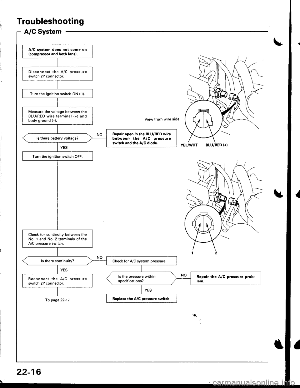
A/C System
I
A/C sy3tem doe! not coms on{cornDrcssor lnd bolh fan3),
Disconnect the A/C pressure
switch 2P connector.
Turn the ignition switch ON (ll).
Measure the voltage between theBLU/RED wire terminal (+) andbody ground {-).
Repeir opon in the BLU/RED wirobotwoon the A/C D.ossuro3witch and the A,/C diode.
Turn the ignition switch OFF.
Check for continuity between theNo. 1 and No. 2 torminals of theA,/C pressure switch.
Check for Ay'C system pressure.
Recon nect the A/C pressure
switch 2P connector.
Repbce the A/C pro$ur6 3witch.
View from wire side
YEL/WHTBLU/RED l+l
fo page 22-17
22-16
\
Page 1035 of 1681
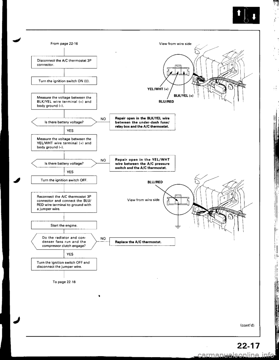
JView from wire sideFrom page 22-16
i,:,
il
rlt'
8LK/YEL l+)
YEL/WHT {+}
View from wire side
BLU/FED
(cont'd)
Turn the ignition switch ON {ll).
Measure the voltago between theBLK/YEL wire terminal (+) andbody ground (-).
Reprir opon in th€ BLK/YEL wir€batween the under-d.sh tuse/relay box rnd the A/C therm6tlt.
ls there battery vohageT
Moasure tho voltage between theYEL,A/VHT wire terminal (+) andbody ground (-).
Repair op6n in the YEL/WHTwire betwGen the A/C pressure
switch snd the A/C thermostat.ls th6re battery voltage?
Turn the ignition switch OFF.
Reconnect the A,/C thermostat 3Pconnector and connect the BLU/RED wire terminal to ground with
Do the radiator and con-denser fans run and thecompressor clutch engage?
Turn the ignition switch OFF anddisconnect the jumper wire.
To page 22'18
22-17
Page 1036 of 1681
Troubleshootang
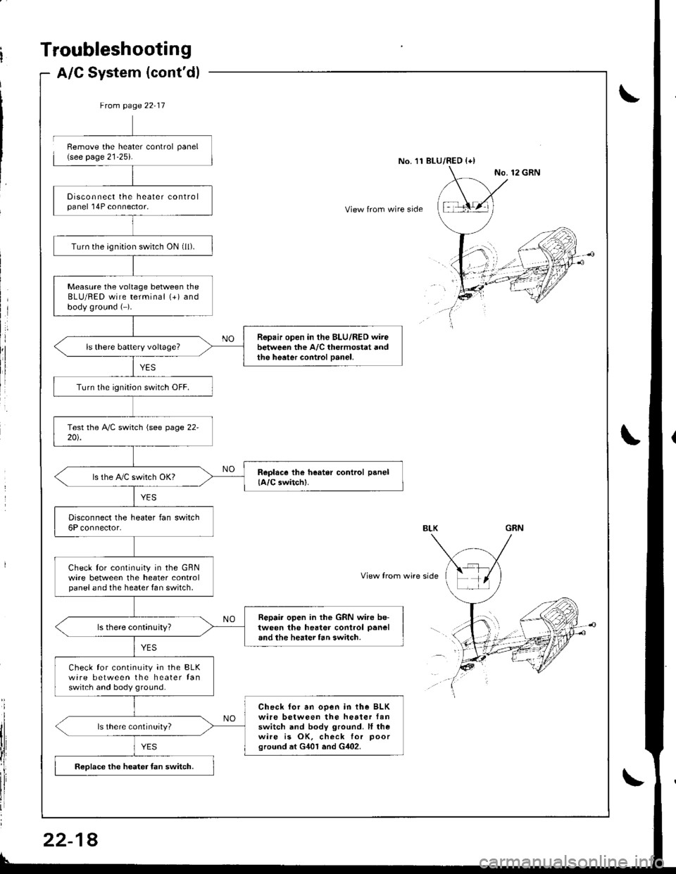
A/C System (cont'd)
8
Ftom page 22-17
Disconnect the heater controlpanel 'l4P connector.
Turn the ignition switch ON (ll).
Measure the voltage between theBLU/RED wire terminal (+) andbody ground (-).
Ropair open in the BLU/RED wirebetween the A/C thermostat andthe heater control Danel,
Turn lhe ignition switch OFF.
ls the PVC switch OKI
Disconnect the heater fan switch6P connector.
Check lor continuity in the GBNwire between the heater controlpanel and the he6ter fan switch,
Repair open in the GRN wire be-tween the hester control panel
and the heater fan switch.
Check for continuity in the BLKwire between the heater fanswitch and body ground.
Check for an ooen in the BLKwire between the hetter fanswitch and body ground. ll rhewire is OK, check for poorground at G401 and G402.
ls there continuity?
Reolace the heater fan switch.
Remove the heater control panel(see page 21-25).No.'11 BLU/RED {+)
View from wire side
View from wire side
22-1
Page 1063 of 1681
Troubleshooting
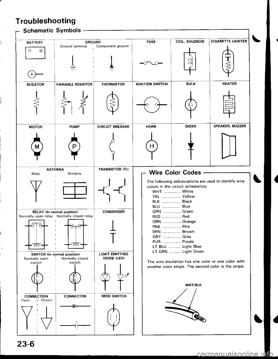
Schematic Symbolsym
BATTEBY
tr3
o-
GROUNDGround terminal Componenr ground
I il
FUSE
rhtdl
l9l.|
CIGARETTE LIGHTER
,A
lrl
Y
RESISTOR
+
T
VARIABLE RESISTOR
TD
=rX
ttf
THERMISTOR
/b'
t=l
v
IGNITION SWITCH
1-\-T- l.--
BULB
A
Y
HEATER
-h
t=l
tr
MOTOR
0
PUMP
A
Y
CIRCUIT EREAKER
I
t
Y
HORN
+
DIODE
+
SPEAKER, BUZZER
D
Mast
Y
ANTtiNNA
T,
TRANSISTOR (Tr)
ll
+1^'l
)
Wire Color Codes
The following abbreviations are used to identify wire
colors in the circuit schematics:
WHT ............ White
YE1 .............. Yellow
81K .............. Black
B1U .............. Blue
GRN ............. Green
RED .............. Red
ORN ............. Orange
PNK .............. Pink
BRN .............. Brown
GRY ............. Gray
PUR .............. Purple
LT BLU ......... Light Blue
LT GRN ......... Light Green
The wire insulation has one color or one color with
another color stripe.'The second color is the stripe.
WHT/BLK
,//,aI,//t- /
R
BELAY lln noNormally open relayrmal position)
Normally closed relay
-tr-f,-
l=T= |
til
trf
CONDENSER
I
T
SWITCH {ln nrNormally openswitch
I
/6\
v
I
)rmal position)Normally closed
I
A
w
I
LIGHT EMITTINGDIODE (LEDI
AJ"
YT
CONNE
V
I
CTIONOutput
J,
CONNECTOR
+>-
l-l'l
REED SWITCH
.K
Irr ]
Y
Page 1105 of 1681
![HONDA INTEGRA 1998 4.G Workshop Manual Fuses
Under-dash Fuse/Relay Box
C920 [To SRS msin harnc$ lc8{,l}lC922 [To ignition rwitchl
C923lTo main wir. harn6! (Cil,alll
C€24 [To m.in wiro hrrno$ lc,l,l2]l
lTo pow.r windowrclayl
CgNlS Oo turn HONDA INTEGRA 1998 4.G Workshop Manual Fuses
Under-dash Fuse/Relay Box
C920 [To SRS msin harnc$ lc8{,l}lC922 [To ignition rwitchl
C923lTo main wir. harn6! (Cil,alll
C€24 [To m.in wiro hrrno$ lc,l,l2]l
lTo pow.r windowrclayl
CgNlS Oo turn](/img/13/6069/w960_6069-1104.png)
Fuses
Under-dash Fuse/Relay Box
C920 [To SRS msin harnc$ lc8{,l}lC922 [To ignition rwitchl
C923lTo main wir. harn6! (Cil,alll
C€24 [To m.in wiro hrrno$ lc,l,l2]l
lTo pow.r windowrclayl
CgNlS Oo turn 3ign.l/h.z.rd rcl.yl
C919 [To root wir. hsmolr {C661ll
al Spare fusel: Option connector (+B)
2: Option conn€ctor (oash lights)3: Option connector (ACC)
4: Option connector {lG2}*: Not us€d
Fusa Number Amp!wire Color
C928 [To r..] window d.toggd r.l.yl
Compon€nt(s) or Circuit(3) Protaqtad
C92l ITo d..hbo.rd wir. h.rness lc551ll
- r-t r-'l r-'t n n r-'t n n r-1 r-'l r-l4 2321 2s 26 27 28 29 30 3t 32 33IJ IJ IJ LI LI IJ LI LJ IJ LI LJ I.J
- r-t n n r-l r-'t r-t r-'l r-1 n r-'t r-1a 12 13 14 15 t6 17 ,t8 19 20 21 22I-J LI IJ IJ tJ LI LI IJ IJ IJ LI IJ
- r-'t |;l n r-1 n |;t r-'t r-t r-1 n r-'ta 12 3 it 5 67 8 910 11
LI IJ IJ IJ LI IJ LI LI I-J LI LJ LI
1204WHT/GRNPower door lock control unit
Not used
10AGRN,4/VHTRear window washer motor
GRN/BLKRear window wioer motor
410 ARED/BLURight headlight (high beam)
10ARED/GRNLeft headlight (high beam), high beam indicator light
Not used
720A.GRN/BLKLeft rear power window motor
a204YEUBLKRight rear power window motor
15 ABLK/YELlgnition coil
10204BLU/BLKPasseflger's power window motor
l1204WHTI/ELPower window master switch, power window control unit
23-48
Page 1115 of 1681
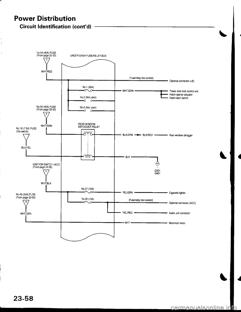
Power Distribution
N0.54 (404)FUSE(From page 23 55)
N0.49 (30A)FUSE(From page 23-55)
Gircuit ldentification (cont'dl
UNDER.DASH FUSEi FELAY BOX
(Fuserelay box sockel)Oplional conneclor (+B)
N0.50 (40A) FUSE(From page 23-55)
'/'/H_'GRN ----- rower door tock controt un,tF Halct op€ler acluatorl- Halch lalcn sw,rm
BLKGFN <- BLKRED - Rear window delogger
N0.16 (7.sA) FUSE(Viaswlch)
f7
IBLUfrEL
IGNITION SWITCHlFrom page 23 56)
ft
IWHT/BLK
"^--f,_
(Fus€irglay box soclel)
G201G401
Cigaretle lighler
Oplional conneclor (ACC)
Audro unil conneclorWHT/GRN
23-58
Page 1130 of 1681
;
Steering Lock Replacement
SRS components are located in this area. Review the
SRS component locations, precautions, and procedures
in the SRS section (23) before performing repairs or ser-
vice.
NOTE: The original radio has a coded theft protection
circuit. Be sure to get the customer's code number before- disconnecting the battery.- removing the No. 47 (7.5 A) fuse trom the under-hood
fuse/relav box.- removing the radio.
After service, reconnect power to the radio and turn it
on. When the word "CODE" is displayed. enter the cus-
tomer's 5-digit code to restore radio operation.
1. Disconnect the negative cable from the battery.
2. Remove ths dsshboard lower cover and knee bolster(s6o p8ge 23-72).
3, Disconnect the 5P connector from the under-dash
fuse/relay box and the 7P connsctor from th€ main
wire harness (see page 23-72l.,
4. Remove the steering column covars (see page
23-721.
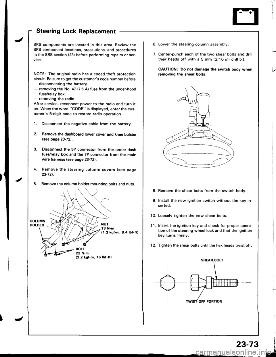
5. Remove the column holder mounting bolts and nuts.
NUT13 N.m(1.3 kgl.m, 9.4 lbt.ftl
BOLT22 N.m(2.2 kgf.m, 16 lbf.ftl
6.
7.
Lower the stee.ing column assembly.
Center-ounch each of the two shear bolts and drill
their heads oft with a 5 mm {3/16 in) drill bit.
CAUTION: Do not damage the switch body when
lemoving th€ sheal bolts.
Remove the shear bolts from the switch body.
Install the new ignition switch without the key in-
serted.
1O. Loosely tighten the new shear bolts.
11. Ins€rt the ignition key and check for proper opera-
tion of the sleering wheel lock and that the ignition
key turns freely.
12. Tighten the shear bolts until the hex heads twist off.
8.
Page 1132 of 1681
![HONDA INTEGRA 1998 4.G Workshop Manual Circuit Diagram (M/Tl
tJ
STARTEBCUT RELAY
)/
ll-G2o1G401
rAa rtFz5- r3
) -rr
CLUTCHINTERLOCKSW]TCH
IGNITIONX SWITCH
!_*",.^-*-G-l
"T"
BTKWHT BLKWHT
llr - tr |
BLKFED 8LU/BLK
- BLK,BE I__-lrror.oo*
I HONDA INTEGRA 1998 4.G Workshop Manual Circuit Diagram (M/Tl
tJ
STARTEBCUT RELAY
)/
ll-G2o1G401
rAa rtFz5- r3
) -rr
CLUTCHINTERLOCKSW]TCH
IGNITIONX SWITCH
!_*",.^-*-G-l
"T"
BTKWHT BLKWHT
llr - tr |
BLKFED 8LU/BLK
- BLK,BE I__-lrror.oo*
I](/img/13/6069/w960_6069-1131.png)
Circuit Diagram (M/Tl
tJ
STARTEBCUT RELAY
)/
ll-G2o1G401
rAa rtFz5- r3
) -rr
CLUTCHINTERLOCKSW]TCH
IGNITIONX SWITCH
!_*",.^-*-G-l
"T"
BTKWHT BLKWHT
llr - tr |
BLKFED 8LU/BLK
- BLK,BE' I__-lrror.oo*
I I
+Yffii'"'Tf'o' | |
u"T-l
i,t^il'r** | |
=-T--. I
twt t
l$*Tl r
IA II
BLK
tY--lt I-|ffim-
|
rl
UNDEB HOOD FUSE/BELAY BOX
No 41 (100A) N0.42 (404)
Page 1133 of 1681
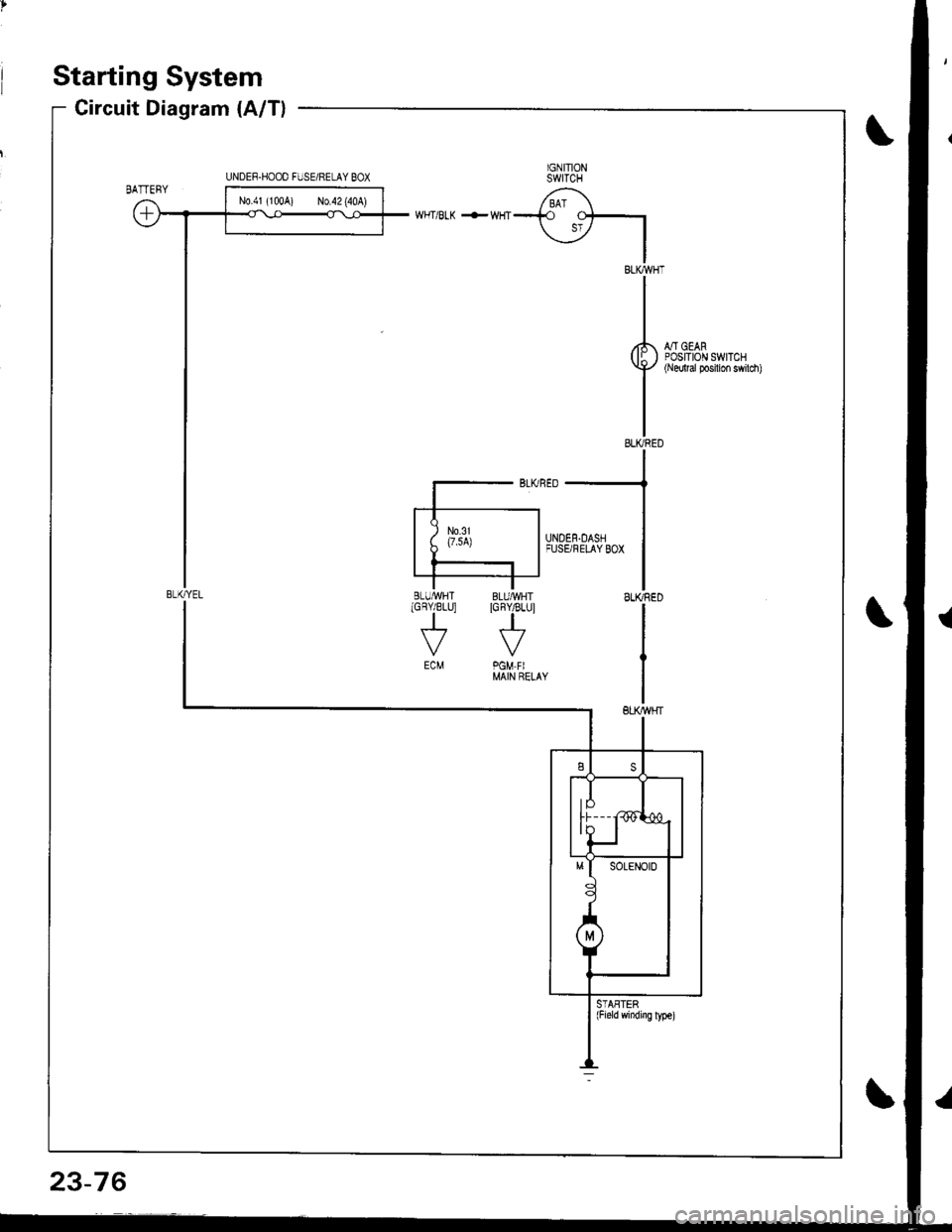
Starting System
Circuit Diagram (A/T)
IGNITIONSWITCH
/ BAT \--i.o
\jz IIBLKWHT
II
I
rl., - oro,( lI ) POStlOr\l swrTcHY+'/ {Nedtal Posilion swilch)
II
IELIVRED
WHT/BLK +WHT
::--JFUSBFELAYBox
ISLIffiED
I
IGBY/BLU]
J
ECM
STASTER(Field windiig ly!€)
UNDEF.HOOO FIJSE/RELAY BOX
BLI(YEL
N0.41 (100A) No.42 (40A)
23-76