ignition HONDA INTEGRA 1998 4.G Workshop Manual
[x] Cancel search | Manufacturer: HONDA, Model Year: 1998, Model line: INTEGRA, Model: HONDA INTEGRA 1998 4.GPages: 1681, PDF Size: 54.22 MB
Page 593 of 1681
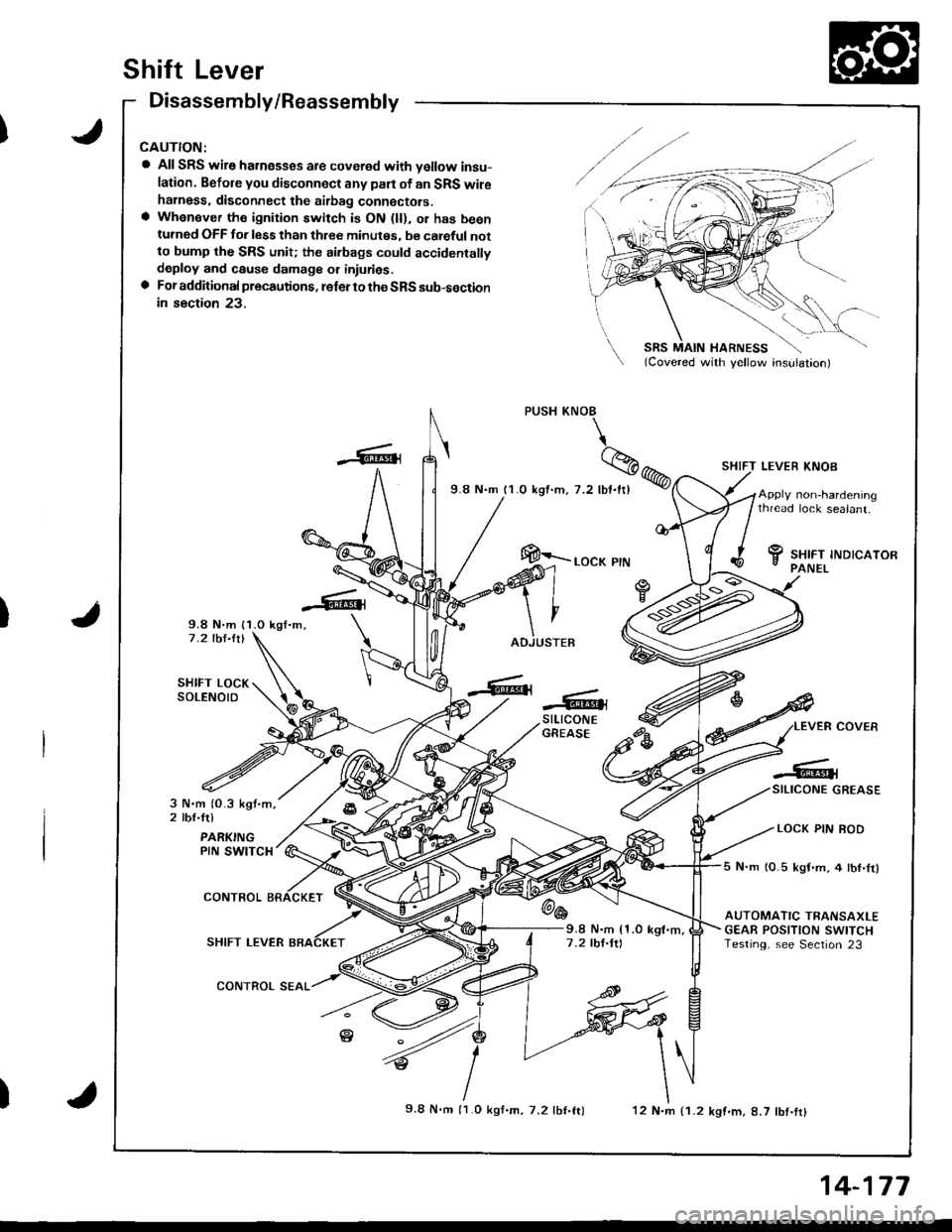
Shift Lever
Disassembly/Reassembly
a All SRS wire harnesses are covered with vellow insu-
lation. Befole you disconnect any part ol an SRS wileharness. disconnect the aitbag connectors.a Whensver the ignition switch is ON (ll), or has beenturned OFF for less than three minutes, be careful notto bump the SRS unit; the airbags could accidentallydeploy and cause damagg or iniuries.a For additional precautions, lefer to the SRS sub-sectionin section 23.
9.8 N.m {1.0 kgl.m,-7 .2 lbl.ltl
SHIFT LOCKSOLENOID
SHIFT LEVER KNOB
5 N.m 10.5 kgf.m,4lbl,Irl
AUTOMATIC TRANSAXLEGEAE POSITION SWITCHTesting, see Section 23
Apply non-hardeningthread lock sealant.
f, sxrrr rruorcaron- PANEL
PUSH KNOB
\
%
9.8 N.m 11.0 kgt.m. 7.2 lbl.ftl
@>.o"* r,"
-6{stLrcoNEGREASE
_GlSILICONE GREASE
' LOCK PIN ROD
3 N.m (O.3 kgt.m,2 tbt'trl
PARKINGPIN SWITCH
@6CONTROL
SHIFT LEVER
CONTROL SEAL
9.8 N.m (1.0 kgl.m,7 .2 tbl.ttl
)9.8 N.m l1.O kgf.m, 7.2 tbt.ft)12 N.m {1.2 kgf.m, 8.7 lbf.fr}
14-177
Page 594 of 1681
I
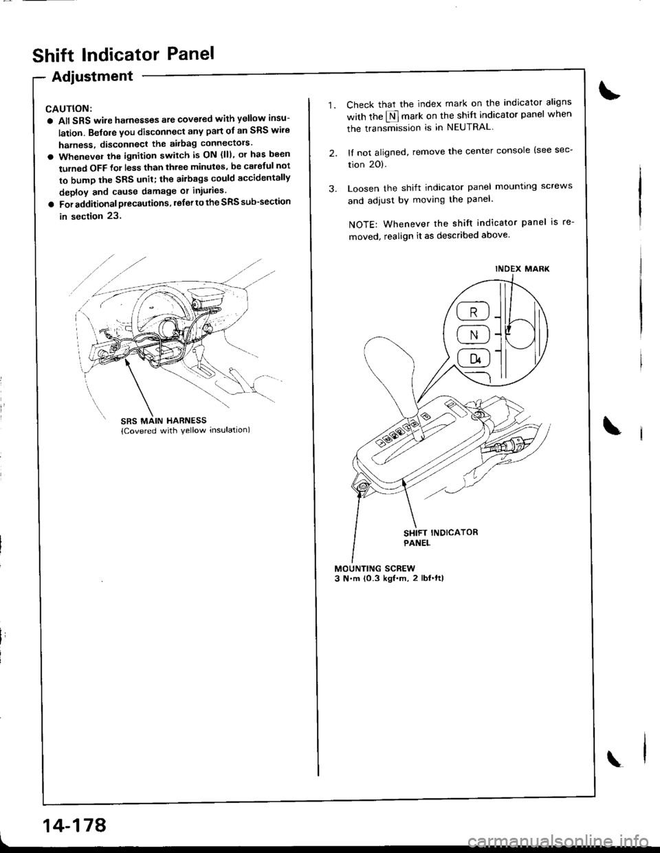
Shift lndicator Panel
Adjustment
CAUTION:
a All SRS wire harnesses ate covered with yellow insu-
lation. Belore you disconnect any part ol an SRS wire
harness, disconnect the airbag connectols'
a Whenever the ignition switch is ON (lll, ol has b€en
tulned OFF lo1 less than three minutes, be calgful not
to bump the SRS unit; the ailbags could accidentally
deploy and cause damage or iniulies.
a For additional precautions, lefer to the SRS sub-section
in section 23.
14-178
1.
3.
Check that the index mark on the indicator aligns
with the $ mark on the shitt indicator panel when
the transmission is in NEUTRAL
lI not aligned, remove the center console lsee sec-
tion 20).
Loosen the shift indicator panel mounting screws
and adiust by moving the Panel-
NOTE: Whenever the shift indicator panel is re-
moved, realign it as described above
INDEX MARK
a;-)\___ti_J -
@-
Page 650 of 1681
Steering
Componsnt Location
lndox
*Stooring Wheel
Removal ....
Disassombly/Ro8$.mbly
Disassombly ......
F08$€mbly
Powcr Stosring Gosrbox
R6moval
............................ 17-3
............. 17 -1
................ 17-16
............................. 17_25
17-30
17.31
.......17-21
Sy3tom DGcription
Fluid Flow Disgram
Steering Pump .............. 17-5
Stocring Goarbox ...17.8
Troublorhooting
Gonoral Troubleshooting .............................. 17.10
Noiso lnd Vibration ...... 17-1i[
Fluid Losk3
lnspoction
Installation
Powor Steering Hos6, Lino3
Roplacom€nt .................. 17.34
Powor Steoring Pump
RGplac6montlolpeqtion lnd Adiu3tm6nl
Stoo.ing Operation
Powor A$bi Chock
with v.hiclo Parked
Stcering Linkage 6nd Goarbox
Pump Bolt
17.18
17.18
17.19
17-20
17.35
t7-36
17 -37
r7-39
Inspoction
................... 17.41
Rack Guide Adiustmont ..........................-.-.-. 17 -21
Ffuid Rcplacemont ........17-21
Pump Prc&suro Chock ...,........................,..,..., 17 -22
Fluid Leakage Inrpection ............................... 17-23
Dissssembly
R€aEs€mbly
In3tallation........... 17_58
Ball Joint Boot Replacem.ni ........................ 17-61
17-U
17.49
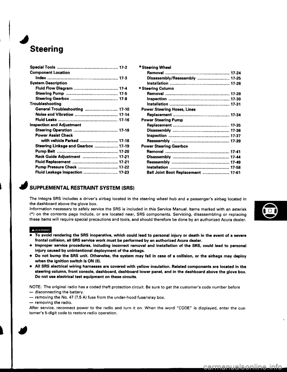
J ,urrar*TNTAL REsrRArNr sysrEM (sRsr
The Integra SRS includes a driver's airbag located in the steering wheel hub and a passenger's airbag located inthe dashboard above the glove box,
Information necessary to safely service the SRS is included in this Service Manual. ltems marked with an asterisk(*) on the contents page include, or are located near, SRS components. Servicing, dissssembling or replacing
these items will require special pr6cautions and tools, and should therefore be done by an authorized Acura dealer.
. To avoid rondoring ths SRS inoparstivo. which could |rad to parsonal iniury or doath in the ov€nt of ! sev6.o
trontal collision, all SRS sarvice work must be perto.med by an authorizod Acura dsalor.. lmpropor 3orvic€ procadures, including inco[6ql rgmoval and inrtallation of the SRS, could l6ad to pgrsonal
iniury clus€d by unintentional doployment of the airbags,. Do nol bump tho SRS unh, (Xherwise, th6 3ystom may fail in cas€ ol a collision, or the airbags may d€ploy
when ths ignition switch is ON {ll).. All SRS electrical wiring harness€s aro covered with yallow insulation. Related component3 are located in ths
stcaring column. tront con3ol6, dashboard, d.shbolrd lower panel, and in the dashboard above ths glove box.
Do not u3o electrical test oquipm€nt on the3e circuii3.
NOTE: The original radio has a coded theft protection circuit. Be sure to get the customer's code number before- disconn€cting the battery.- removing the No. 47 (7.5 A) fuse from the under-hood fuse/relay box,- removing the radio.
After service, reconnect power to the radio and turn it on. When the word "CODE" is displayed. enter the cus-
tomer's 5-digit code to restore radio operation.
Page 673 of 1681
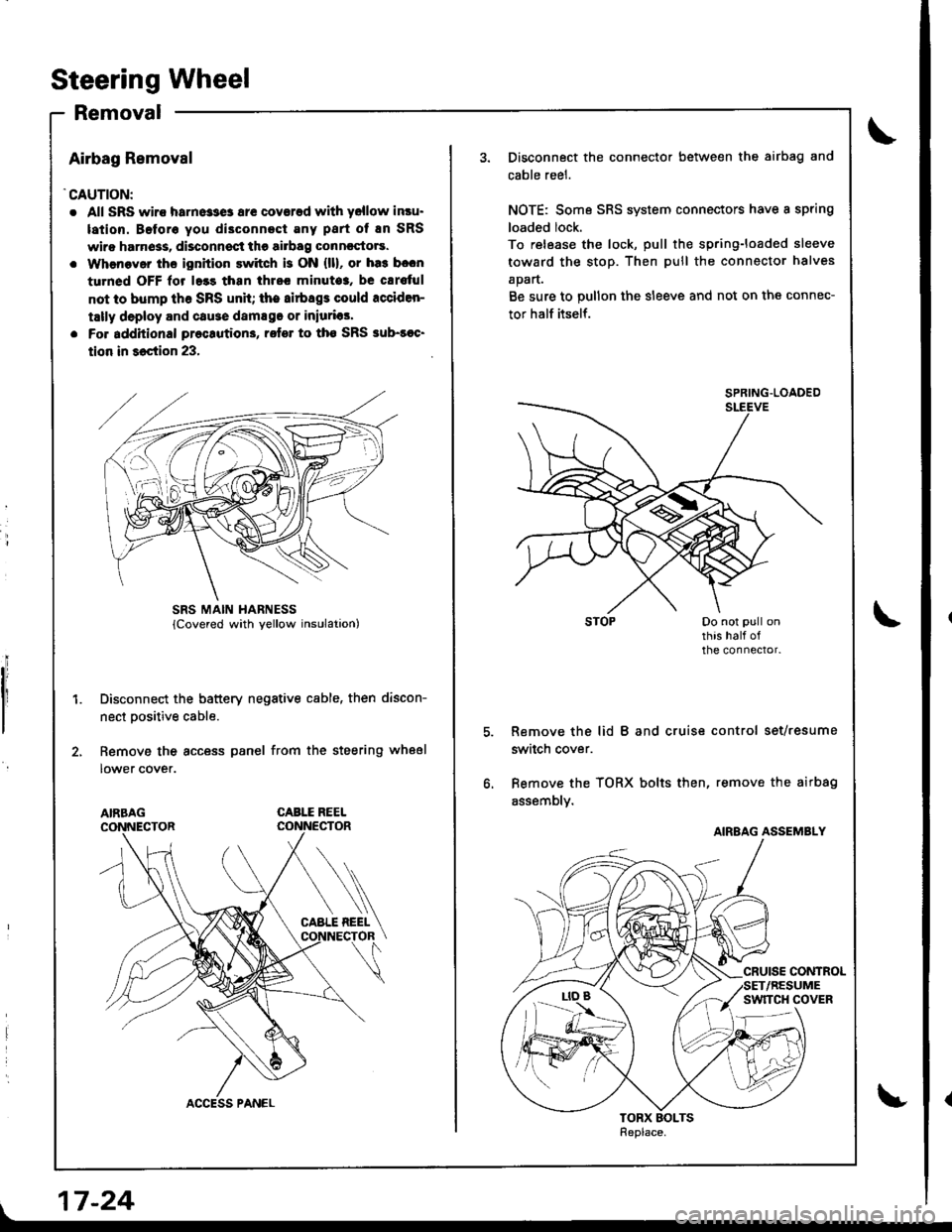
Steering Wheel
Removal
Airbag Removal
'CAUTION:
. All SRS wiro harne33e3 ar€ coverad with yellow insu.
lation. Beforo you di3connect Eny part of En SRS
wiro harn6ss, disconnsct the airbag conncctors.
. Whenaver ths ignition switch is ON {ll}, or ha3 b.cn
turned OFF lor l.3s than thrcc minuto3, be cErs{ul
not to bump th6 SRS unh; the airbags could rcciden-
tally deploy and cause damsgo or iniurias'
. Fo. additional preclution3, rofer to tho SRS sub-soc'
tion in 36ction 23,
Disconnect the battery negative cable, then discon-
nect Dositive cable.
Remove the access panel from the steering wheel
lower cover.
CABLE REEL
L
SRS MAIN HARNESS
17-24
Disconnect the connector between the airbag and
cable reel.
NOTE: Some SRS system connectors have a spring
loaded lock.
To release the lock, pull the spring-loaded sleeve
toward the stop. Then pull the connector halves
apart.
Be sure to pullon the sleeve and not on the connec-
tor half itself.
Remove the lid B and cruise control set/resume
switch cover.
Bemove the TORX bolts then, remove the airbag
assembly.
SPRING.LOADED
AIRBAG ASSEMBLY
Page 676 of 1681
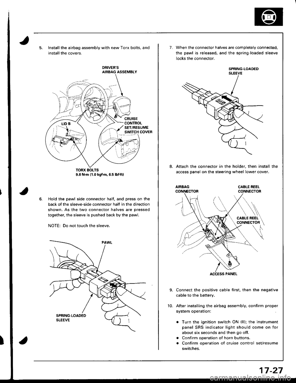
Installthe airbag assembly with new Torx bolts, and
installthe covers.
cRursECONTROLSET/RESUMEswtTcH covER
Hold the pawl side connector half. and press on the
back of the sleeve-side connector halt in the direction
shown. As the two connector halves are pressed
together, the sleeve is pushed back by the pawl.
NOTE: Do not touch the sleeve.
7.When the connector halves are completely connected.
the pawl is released. and the spring loaded sleeve
locks the connector.
SPRING.LOADEDSLEEVE
Attach the connector in the holder, then install the
access panel on the stee.ing wheel lower cover.
Connect the positive cable first. then the negative
cable to the battery.
After installing the airbag assembly, confirm proper
system operation:
. Turn the ignition switch ON (ll); the instrument
panel SRS indicator light should come on for
about six seconds and then go off.
. Confirm operation of horn buttons.
. Confirm operation of cruise control sevresume
switches.
10.
17-27
Page 677 of 1681
Steering Golumn
Removal
I
a All SRS wire harnesses are covered with yellow insu-
lation. Before vou disconnect any pan of an SRS wire
harness, disconnect the airbag Gonnectors.
a Whenever the ignition switch is ON (lll, or has been
turned OFF for less than three minutes, be carelul not
to bump the SRS unit; the airbags could accidentally
deploy and cause damage or iniuries.
a For additional precautions, lelel to the SRS sub-section
in section 23.
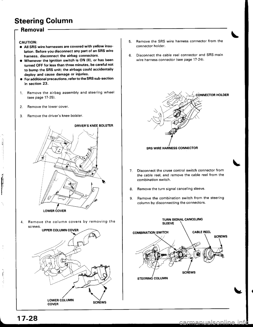
1. Remove the airbag assembly and steering wheel
(see page 17-25).
2. Remove the lower cover.
3. Remove the driver's knee bolster,
Remove the column covers by removing the
screws.
'//
,,1G
LOWER COVER
17 -28
1.
9.
Remove the SRS wire harness connector from the
connector holder.
Disconnect the cable reel connector and SRS main
wire harness connector (see page 17-24).
CONNECTOR HOI-DER
SRS WIRE HARNESS CONNECTOR
Disconnect the cruse control switch connector from
the cable reel, and remove the cable reel trom the
combination switch.
Remove the turn signal canceling sleeve.
Remove the combination switch from the steering
column by disconnecting the connectors.
Page 678 of 1681
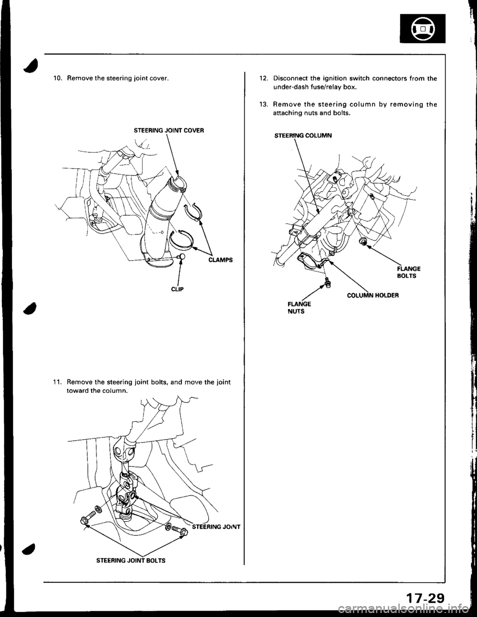
10. Remove the steering joint cover.
Remove the steering joint bolts, and move the iointtoward the column.
11.
JOINT COVER
12.
'13.
Disconnect the ignition switch connectors from the
under-dash fuse/relay box.
Remove the steering column by removing the
aftaching nuts and bolts.
17-29
Page 679 of 1681
Steering Column
Inspection
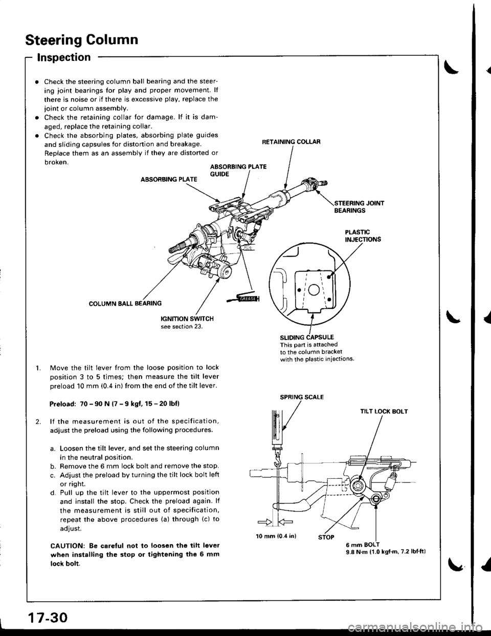
Check the steering column ball bearing and the steer-
ing joint bearings for play and proper movement. ll
there is noise or if there is excessive plav, replace the
ioint or column assembly.
Check the retaining collar tor damage. lf ir is dam'
aged, replace the retaining coilar.
Check the absorbing plates, absorbing plate guides
and sliding capsules for distonion and breakage.
Replace them as an assembly if they are distorted or
DroKen.
ABSORBING PLATE
COLUMN SALL BEANING
IGNITION SWITCHsee section 23.
Move the tilt lever from the loose position to lock
position 3 to 5 times; then measure the tilt lever
preload 10 mm (0.4 in) from the end of the tilt lever.
Preload: 70-90 N {7 -9 kgl, 15-20 lbll
lf the measurement is out of the specification,
adjust the preload using the following procedures.
a. Loosen the tilt lever, and set the steering column
in the neutral position,
b. Remove the 6 mm lock bolt and remove the stop.
c. Adjust the preload by turning the tilt lock bolt left
or right.
d. Pull up the tilt lever to the uppermost position
and install the stop. Check the preload again. lf
the measurement is still out of specification,
repeat the above procedures (a) through (c) to
adjust.
CAUTION: Be carelul not to loosen the lilt lsvel
when installing the stop or tightening the 6 mm
lock bolt.
RETAINING COLLAR
AESORBING PLATE
JOINTBEARINGS
PLASTICINJECTIONS
This pan is attachedto the column bracketwith the plastic iniectaons.
t
SPRING SCALE
TILT LOCK BOLT
17-30
9.8 N.m (1.0 kst.m, 7.2 lblft)
t
{
I
Page 681 of 1681
Steering Column
Installation (cont'dl
CAUTION:
a All SRS wire harness€s are covored with yollow insu-
lation. B€fors you disconnect any part of an SRS wire
harness. disconnoct the airbag connoctois.
a Whenever the ignition switch is ON (lll, or has beon
turned OFF for less than throo minutos, be caleful not
to bump the SRS unit; ths airbags could accidsntslly
deploy and caus€ damago or iniuries.
a For additionalpracautions, reter to the SRS sub-section
in section 23,
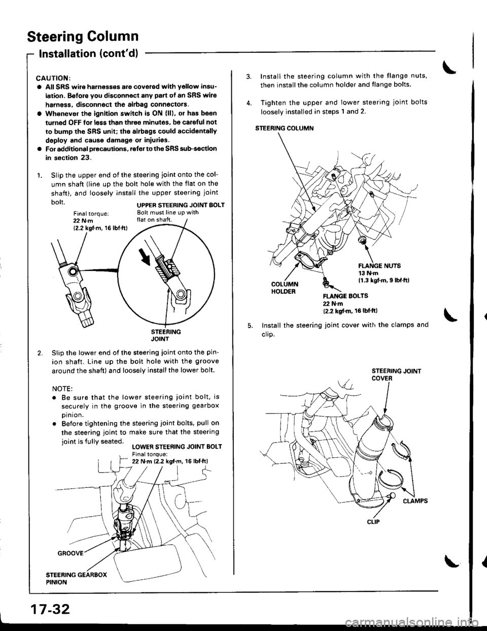
1. Slip the upper end of the steering joint onto the col-
umn shaft (line up the bolt hole with the flat on the
shaft). and loosely install the upper steering joint
bolt UPPER STEERTNG JorNT BoLT
STEERINGJOINT
Slip the lower end of the steering joint onto the pin-
ion shaft. Line up the bolt hole with the groove
around the shaft) and loosely installthe lower bolt.
NOTE:
. Be sure that the lower steering joint bolt, is
securely in the groove in the steering g€arbox
prn ron.
. Before tightening the steering joint bolts, pull on
the steering ioint to make sure that the steering
ioint is fullY seated.LOWER STEERING JOINT BOLT
Fin6ltorque:22 N.m12.2 kgf.m, 16 lbf.ft)
17-32
Install the steering column with the flange nuts,
then installthe column holder and flange bolts.
Tighten the upper and lower steering joint bolts
loosely installed in steps'l and 2.
STEERING COLUMN
FLANGE BOLTS22 N'm(2.2 kgt'm' 16lbf'ftl
Install the steering joint cover with the clamps and
cllP.
CLIP
\{
Page 682 of 1681
9.
1.
8.
11.
10.
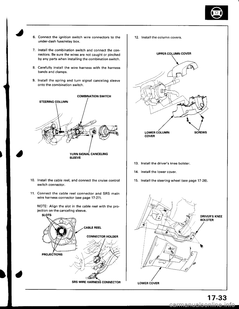
Connect the ignition switch wire connectors to the
under-dash fuse/relay box.
Install the combination switch and connect the con,
nectors. Be sure the wires are not caught or pinched
by any parts when installing the combination switch.
Carefully install the wire harness with the harness
bands and clamps.
Install the spring and turn signal canceling sleeve
onto the combination switch.
Install the cable reel, and connect the cruise control
switch connector.
Connect the cable reel connector and SRS main
wire harness connector (see page '17-27).
NOTE: Align the slot in the cable reel with the pro-jection on the canceling sleeve.
CABLE REEL
CONNECTOR HOLDER
COMBINATION SWITCH
SLEEVE
SRS WIRE
17-33
12. Installthe column covers.
UPPER COLUMN COVER
LOWER COLUMNCOVERscREws
13.
14.
Install the driver's knee bolster.
lnstall the lower cover.
Install the steering wheel (see page 17 26).
LOWEF COVER