HONDA INTEGRA 1998 4.G Workshop Manual
INTEGRA 1998 4.G
HONDA
HONDA
https://www.carmanualsonline.info/img/13/6069/w960_6069-0.png
HONDA INTEGRA 1998 4.G Workshop Manual
Page 996 of 1681
qrt
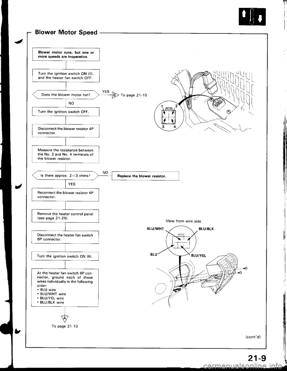
View from wire side
BLU/BLKBLU/WHT
1
To page 21- 1O
ii!
i'l! |
f
'tr
t
!
I
!I
tl
\\
BLU/YEL
l'r
Elowor motor runs, but one ormole speeds sr€ inoperative,
Turn the ignition switch ON lll),and the heater fan switch OFF.
Does the blower motor run?
Turn the ignition switch OFF.
Measure the resistance betweenthe No. 2 and No. 4 terminals ofthe blower resistor.
ls there approx. 2-3 ohms?
Remove the heater control panel(see page 21-25).
Turn the ignition switch ON (ll).
At the heater fan switch 6P con-nector, ground each of thesewires individually in the followingorder:. BLU wire. BLUMHT wire. BLU/YEL wire. BLU/BLK wire
To page 21 10
(cont'd)
21-9
Page 997 of 1681
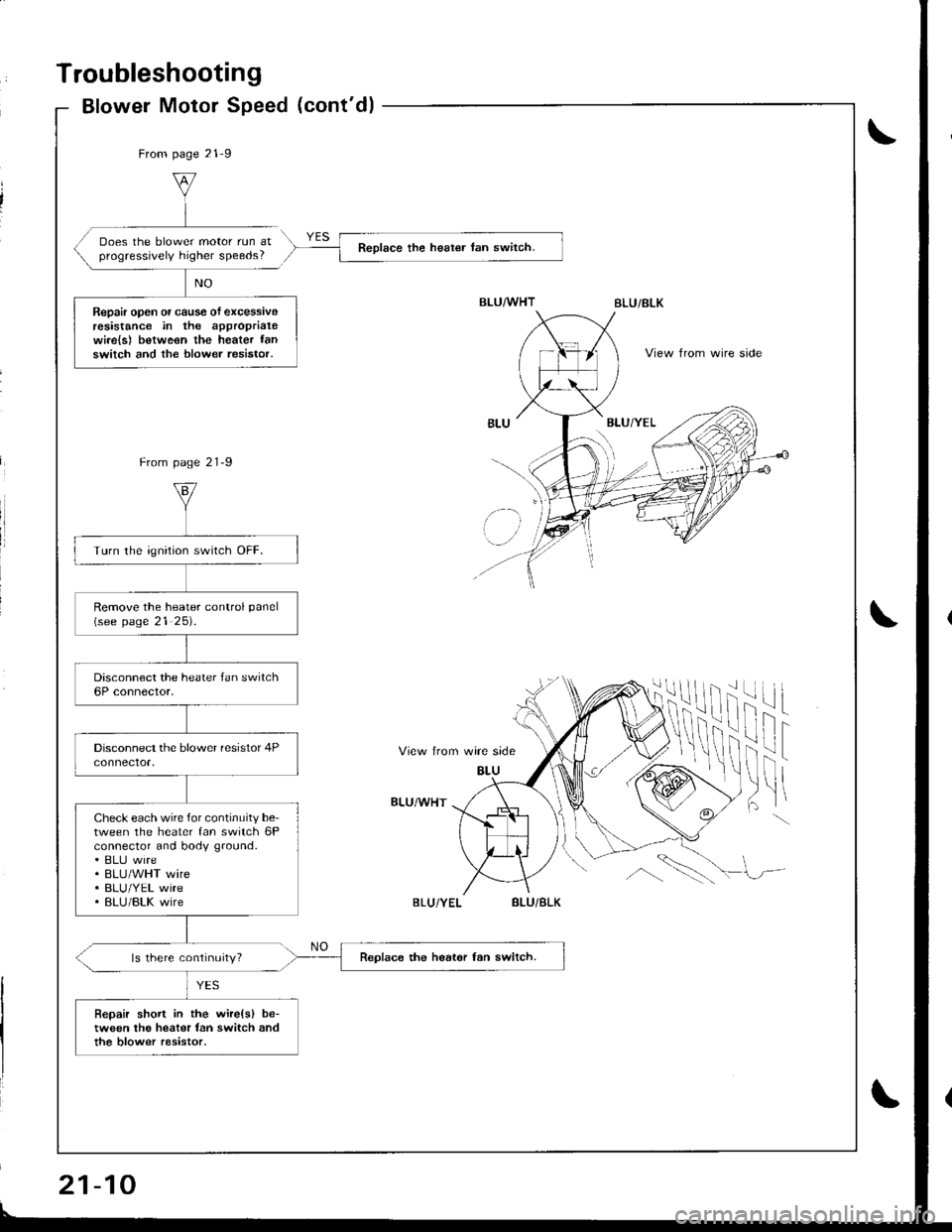
Troubleshooting
Blower Motor Speed (cont'dl
From page 21-9
Does the blower motor run atprogressively higher speeds?Reolace the heat€r tan switch.
Repair open or cause of excessiveresistance in the approprialewi.e{s) betweon the heater fanswitch and the blower resistor.View from wire side
From page 21-9
View trom wire side
BLU
ilif
fril t
)ltBLU/WHT
ls there continuity?
BLU/BLK
BLU
' lz-
Turn the ignition switch OFF.
Remove the heater conlrol panel(see page 21 25).
Check each wire for continuity be-tween the heater fan switch 6Pconnector and body ground.. ELIJ wire. BLU/WHT wire. BLU/YEL wire. BLU/BLK wire
Replace the heat6r fan switch.
Bepair short in the wire(sl be-tween the heater fan switch andthe blow€r resistor.
If
\!,\
BLU/BLK
21-10
Page 998 of 1681
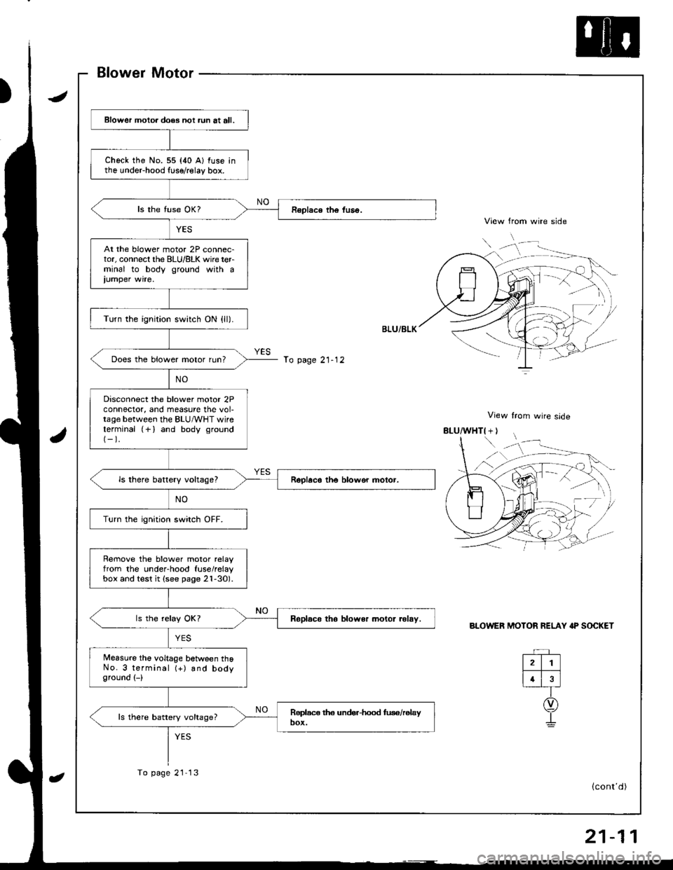
Blower Motor
View from wire side
View from wire slde
BLOWER MOTOR RELAY IP SOCKET
Blower motoa does not aun at all.
check the No. 55 {40 A} fuse inthe undeFhood fuse/relay box.
At the blower motor 2P connec-tor, connecl the BLU/8LK wire terminal to body ground with a
iumper wire.
Turn the ignition switch ON {ll).
Does the blower motor run?
Disconnect the blower motor 2Pconnector, and measure the vol-tage between the BLU/vVHT wireterminal (+) and body ground(-).
ls there battery vokagel
Turn the ignition switch OFF.
Rernove the blower motor relayfrom the under-hood fuse/relaybox and test it (see page 2l-30).
Roplsco tho blower motor .olsy.
Measure the voltage between thoNo. 3 terminal (+) and bodyground (-)
ls there battery voltage?
To page 21- 12
To page 21 13
rD
(cont'd)
Page 999 of 1681
Troubleshooting
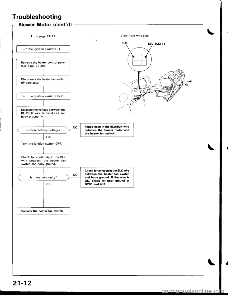
Blower Motor (cont'd)
From page 21-11\View from wire side
8LU/BLK( + I
Turn the ignition switch OFF.
Remove the heater control panel(see page 21-25).
Turn the ignition switch ON lll).
Measure the voltage between theBLU/BLK wire terminal {+) andbody ground (- ).
Repair open in the BLU/Bl-K wir6between the blowea motor andthe hoster lsn switch.ls there battery voltage?
Turn the ignition swirch OFF.
Check for continuity in the BLKwire between the heater fanswitch and body ground.
Check fo. an oDen in th6 8LK wirebotwo€n th€ haat€r tan switchand body ground. ll th6 whe isOK. check tor poor ground atG201 and 401.
Rsplac€ the heat€r fan switch.
ls there continuity?
Page 1000 of 1681
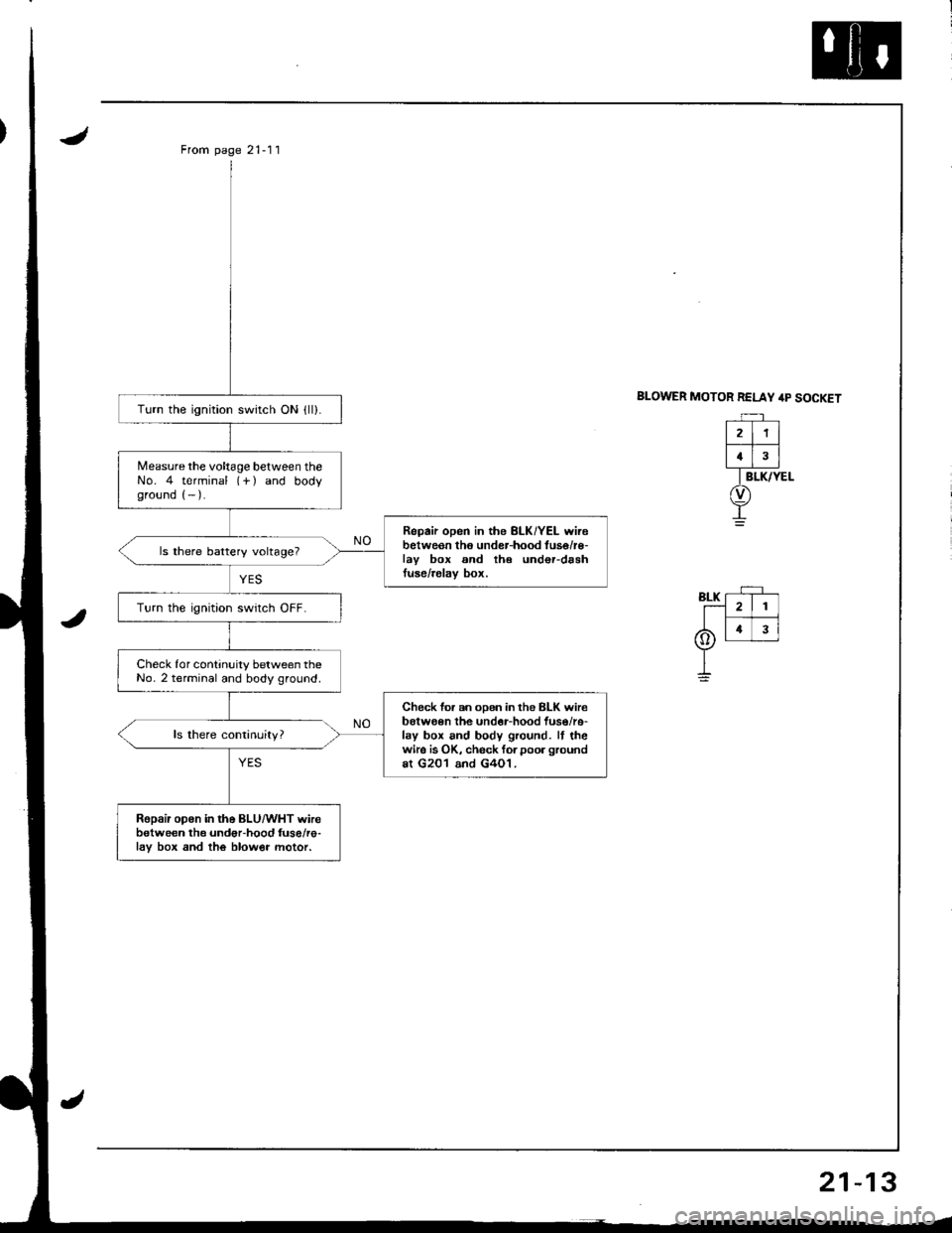
From page 21-11
BLOWER MOTOR RELAY /rp SOCKETTurn the ignition switch ON {ll).
Measure the voltage between theNo. 4 terminal (-f ) and bodyground (- ).
Repair open in the BLK/YEL wirebetweon tho under-hood tuse/r€-lav box and th€ und€r-drshtuse/relav box.
ls there battery voltage?
Turn the ignition swrtch OFF.
Check for continuity between theNo. 2 terminal and body ground.
Check for an oDen in the BLK wir€belween the undor-hood fuso/re-lay box and body ground. It thewire is OK, check forpoor groundat G201 and G4O1.
Ropair open in the BLU/WHT wirebetween the undor-hood fuse/re-lav box and the blow€r motor.
21
4
Page 1001 of 1681
Troubleshooting
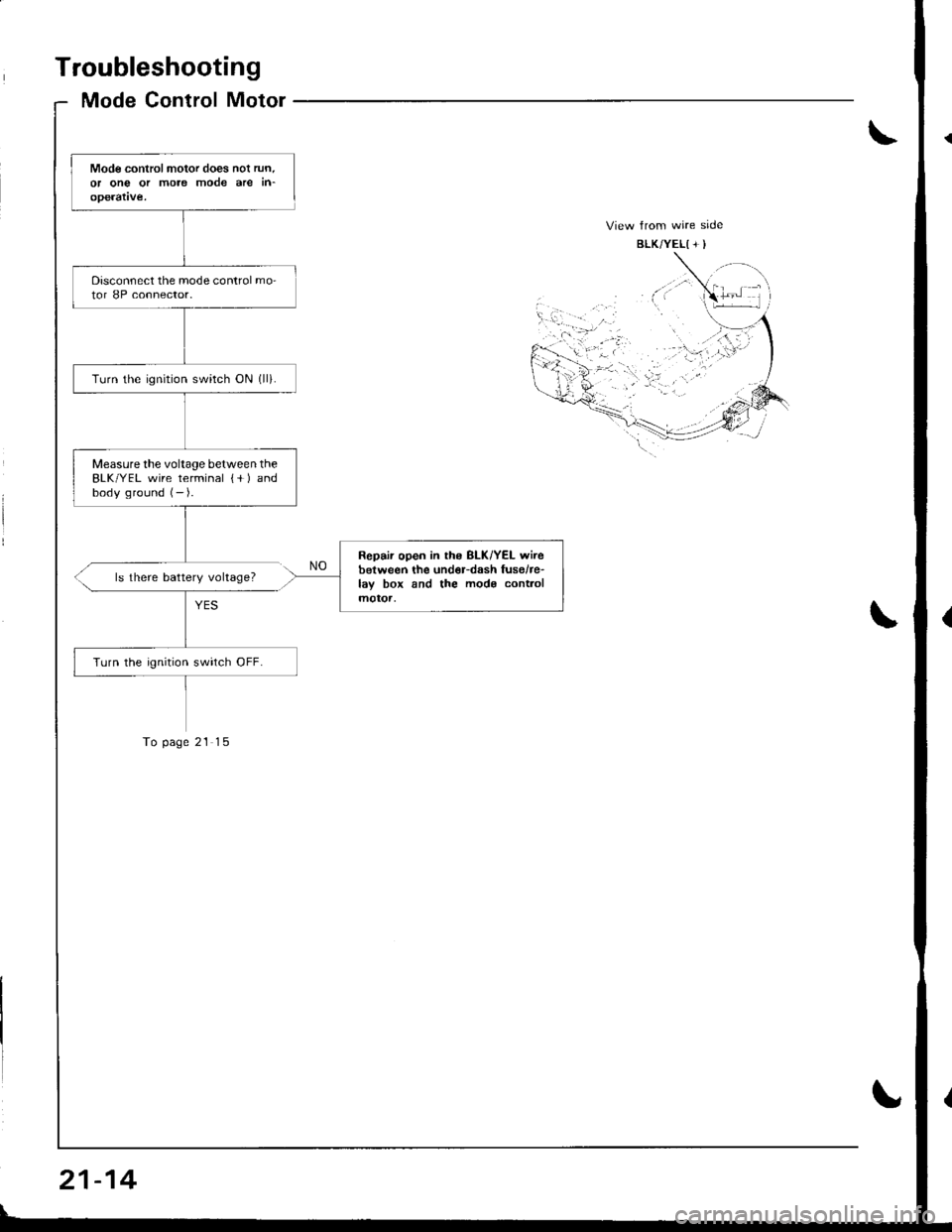
Mode Control Motor
Mode controlmotor does nol run.or ong or more mode are in-operatve.
Disconnect the mode control mo-tor 8P connector.
Turn the ignrtion switch ON (ll).
Measurethe voltage between theBLK/YEL wire terminal {+ ) andbody ground (- ).
Repair open in ths BLK/YEL wirebetween the und€r-dash fusehe-lay box and the mods cont.olmotoa,
Turn the ignition swirch OFF.
ls there battery voltage?
To page 21 15
21-14
Page 1004 of 1681
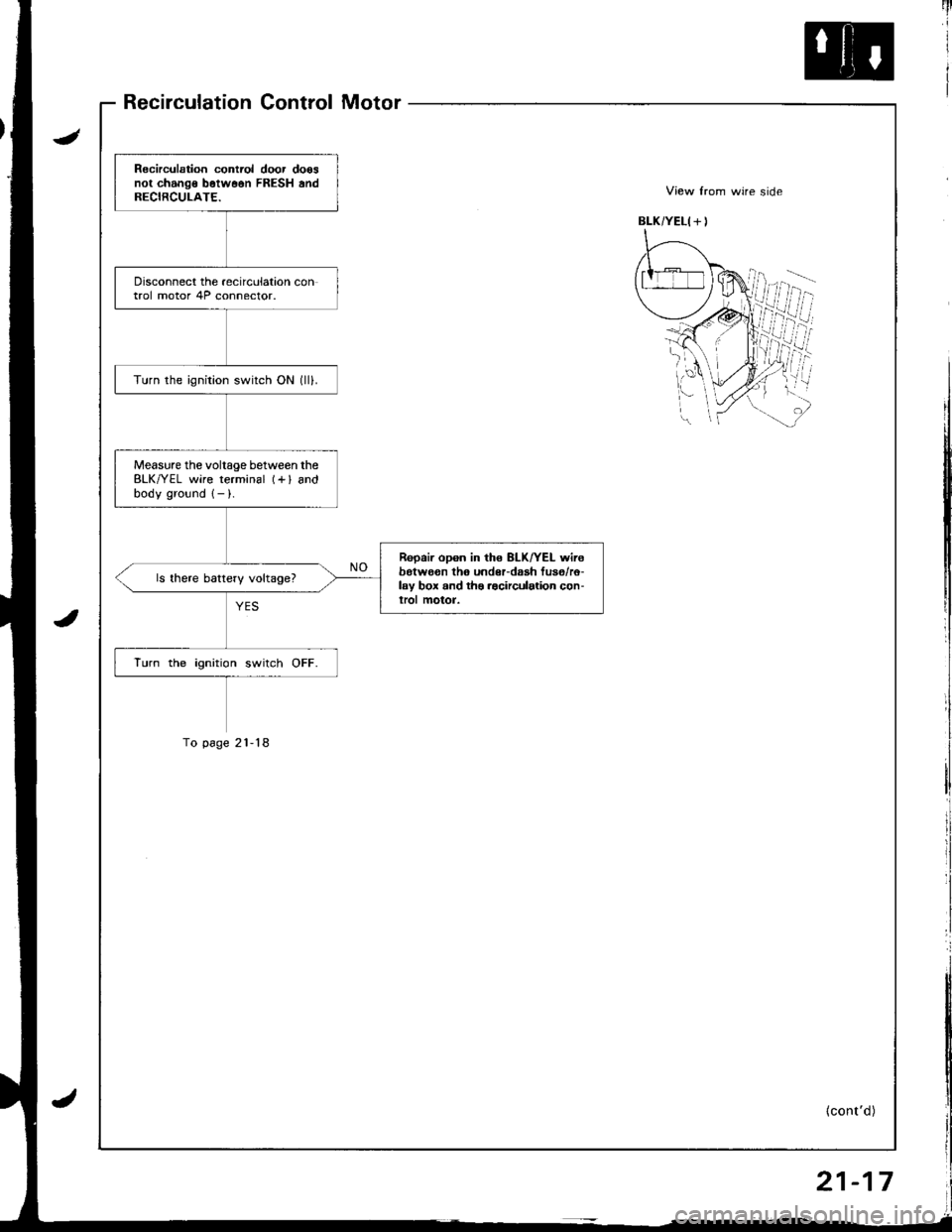
Recirculation Control Motor
Recirculation contiol door doosnot change b6tw66n FRESH andRECIRCULATE.
Disconnect the recirculation control motor 4P connector.
Turn the ignition switch ON (lll.
Measure the voltage between theBLK/YEL wire terminal (+l andbodv ground 1- ).
Repair opon in the 8LK/YEL wirebotwo€n th6 undeFdaah fus6/r6-lay box and ths .acirculation con-lrol motor.
ls there battery voltage?
lurn the ignition switch OFF.
To p6ge 21-18
{cont'd)
21-17
Page 1027 of 1681
From page 22 8
RADIATORFAN RELAY
l-'--l
| 2 |
[T;]
I BrK/YEt
o)
I
RELAY 4P SOCKET
Disconnect the,umper wire andturn the ignition switch ON (II).
Measure the voltage between theNo. 4 terminal (+i and bodyground ( ).
Ropair op€n in the GRN wire be-tween the undor-hood Iuse/.elay box and the A/C diode.
ls there battery voltage?
Repair open in the BLK/YEL wirebotwean the under-hood tuse/relay box snd the under-daahfuso/relay box,
22-9
Page 1029 of 1681
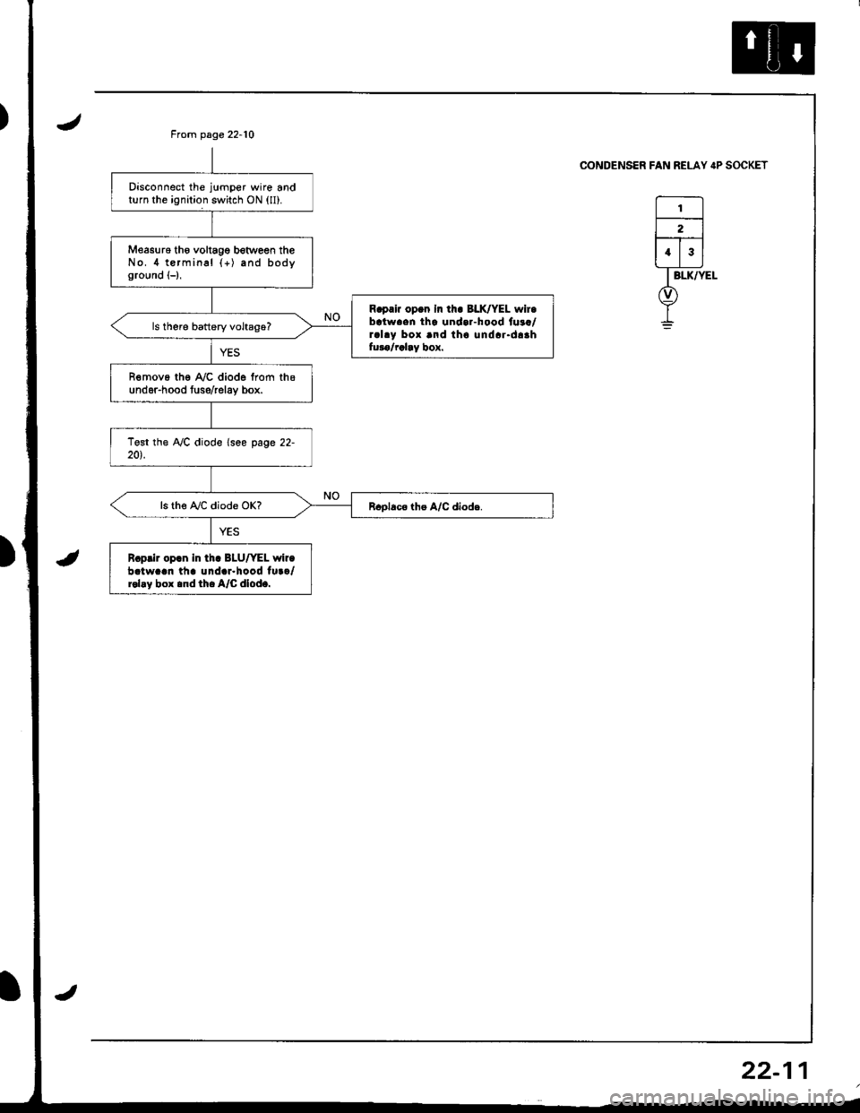
Disconnect the jumper wire andturn the ignition switch ON (ll).
Measu16 tho voltagg botween theNo.4 terminal {+) and bodyground (-),
R.prir op.n In th. BLK/YEL wir.batwaen tha undar-hood fuaa/ral.y box and tho undar.daahfuro/rclay box.
R€move the A,/C diode from thsund6r-hood tuso/relav box.
ls the A,/C diode OK?
R.prir op.n in tha BLU/YEL wir.batw..n th. und.r.hood tu../rol.y box .nd th. A/C dlod..
From page 22-10
CONDENSER FAN RELAY IP SOCKET
I
22-1
Page 1030 of 1681
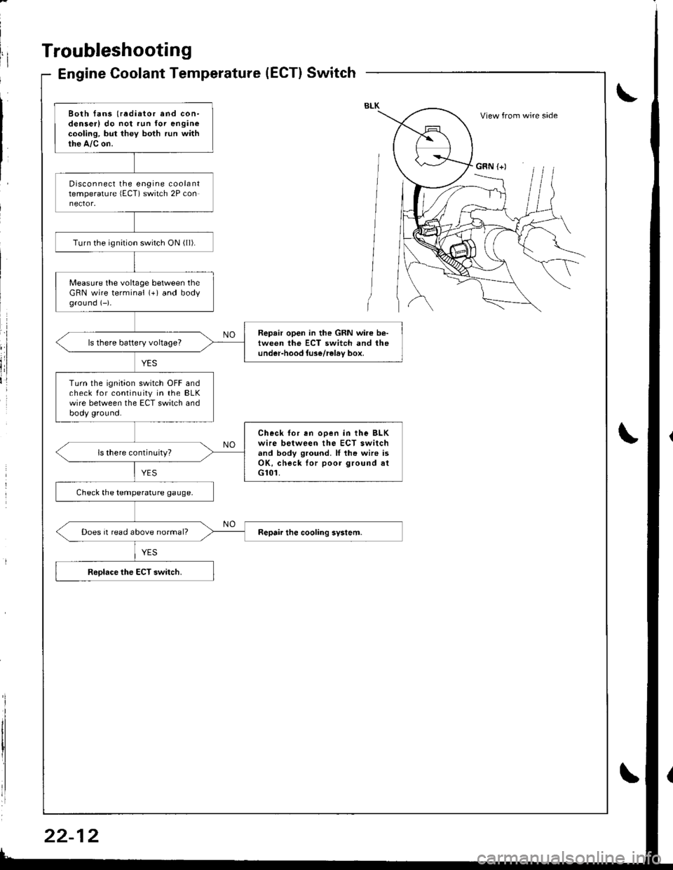
Troubleshooting
Engine Coolant Temperature(ECT}Switch
Both fans (radiator and con-denserl do not run for enginecooling, but they both run withthe A,/c on.
Disconnect the engine coolanttemperature lECT) switch 2P con
Turn the ignirion switch ON ( ll).
Measure the voltage between theGRN wire terminal (+) and bodyground (-)-
Repair open in the GRN wire b€-tween the ECT switch and theunder-hood luse/rel6v box,ls there battery voltageT
Turn the ignition switch OFF andcheck for continuity in the BLKwire between the ECT switch andbody ground.
Check for en ooen in the BLKwire between the ECT switchand body ground. ll th. wire isOK, check lor poor ground atG101.
ls there continuity?
Check the temperature gauge.
Does it read above normal?
View from wire side
GRN (+)
![HONDA INTEGRA 1998 4.G Workshop Manual From page 22 8
RADIATORFAN RELAY
l---l
| 2 |
[T;]
I BrK/YEt
o)
I
RELAY 4P SOCKET
Disconnect the,umper wire andturn the ignition switch ON (II).
Measure the voltage between theNo. 4 terminal (+i and b HONDA INTEGRA 1998 4.G Workshop Manual From page 22 8
RADIATORFAN RELAY
l---l
| 2 |
[T;]
I BrK/YEt
o)
I
RELAY 4P SOCKET
Disconnect the,umper wire andturn the ignition switch ON (II).
Measure the voltage between theNo. 4 terminal (+i and b](/img/13/6069/w960_6069-1026.png)
