HONDA INTEGRA 1998 4.G Workshop Manual
Manufacturer: HONDA, Model Year: 1998, Model line: INTEGRA, Model: HONDA INTEGRA 1998 4.GPages: 1681, PDF Size: 54.22 MB
Page 1551 of 1681
![HONDA INTEGRA 1998 4.G Workshop Manual Security System (contd)
NOTE: Wires that look likethis 5--------5 are part of the ootional
aY cz.tz ||rrrur oPcn rnpur ]wHr RED ll P&?ir rz
I .- - ro 6___z_|f__________Jlf
8,"hT" ll ll see Trunk o"n HONDA INTEGRA 1998 4.G Workshop Manual Security System (contd)
NOTE: Wires that look likethis 5--------5 are part of the ootional
aY cz.tz ||rrrur oPcn rnpur ]wHr RED ll P&?ir rz
I .- - ro 6___z_|f__________Jlf
8,"hT" ll ll see Trunk o"n](/img/13/6069/w960_6069-1550.png)
Security System (contd)
NOTE: Wires that look likethis 5--------5 are part of the ootional
aY cz.tz ||rrrur oPcn rnpur ]wHr RED ll P&?ir rz
I .- - ro 6___z_|f__________Jlf
8,'"'hT" ll ll see Trunk o"n*i l
t"t*
,, V P,'::.^
Lid Open or >-a
r.I-.;.-,:1 UNDER. Security System harness installed between factory harness connectors.
I { i":"",'# | !.o.^o-g sEcuRrrY
I J t$r- i ;Eiii I c"itrns Door I coNrBoL
L^*-^lt-jF,i[,, i lg5 fffJ I','#llitT iv,j:]'",,
t-l,",,*,"""^'"*f,'''o" ll ffi dlffi'r,'*ir*'
[*l
.*"*1*,
1
ll
*""&
L= Jsts.""ll
.L:-.ntt
"l1",.,."""'o.L---- _I,&:1*,"","11
'I:;"12 * H4rqH
""
I
.,"""ffi:;:91., ll ':L--:SI{ ,l"u.u
-='1=rr^,."-"" l"''qi:'':* ll ilSl:il,:f,-,. i |.�l;H,I!il""
li!qr,,n.t !fiJ"''
I ll lFhalchooen ' HPrata'�te
ru;;i.- >1 r i ll :tl-------i "if
"*'
L---ilr-J I ll 1gcs28 |
---:Ij1'-----l ll "-l'nnn'''o--,..^,.^ I "".
."*":['*'-
ll ;;:, *lH'T,'*i'*"
a, o"n ".oI P,olo s6
r----{-- 'NDER-DAsFI
! ,. I "oo. I FUSE;BELAY
L----V-J I lr 1gcs28 I
---:{j1'-----l il "-l
_''.""o,"""0 | _"""o,ounocnNe.u I l-o 'rr{ oisiriourtn. or{ oLtrioutron,
L'�"---J_.i14 lr c44e
----1---
'":;1"_.
""" ".u ll
*o'o'
11"""
," I ",,,
*"{ "." ll ".*l pase u, u.* | pase 14-8'
""^l.:fit*t" gn:+r- ;t'"*."
f+J l#-*ll
V
'cnrneof 99,to;t,u :iio_,_o.0,,
| | cFN BLu ll s"" u cnr neo I-:- -Gc--open - -t-Indicator ll., Lr cFN RED
(ln-line connector;,
"""",u! .,o""".0! ',-
____l::.*"! .,o"n",'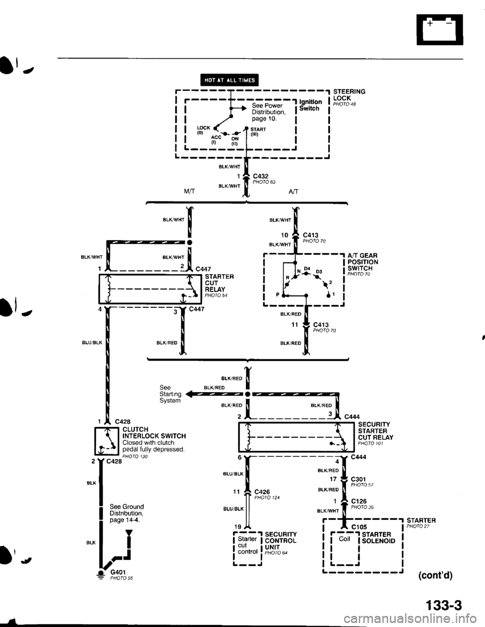
J
r-----T-
I r----T--"-==-1 lgnition
| | f--r i[!,iii[ir" lswncn
| | -/ Pase 10 lI I !'gcK < , sraRr I!!3"-.:^.*--1tli"' | |l l tf" p* l" | |I L----J!L----.1 |
T---------erxrwur It li9,o:,2",
M/r BLK wHr
I Nl
STEERINGLOCK
l
".--",f,
-ra
1r:I
10
BLKryI/HT
c413
A/T GEARPOSITIONswtTcHr..1STABTERcuTRELAY\,
ar., I
c413
JBLK/REO
11
l
".r".lt*'"totrba".s.::ri-,**
1 ^ C42ASECURITY
ffi P*tLt*%"*r*r"" I f--------
{ lsrnnren
l}l$!"i',:in'Hll;[* '.' n.1lt15*'
'"f--:
T[**,-- td:':i
! Ur,run:
"':ljl "T:'+-':- -r.sriqrF^
I """'-- rgA i I cros ai.i&li,
"."1 I i:T;li.p"d,El[ ii-";ls8iEl'J"i
l:j L"l:i'*'t- il--i it
1- c+ot L I
= PHero 56 (cont'd)
---a.
133-3
Page 1553 of 1681
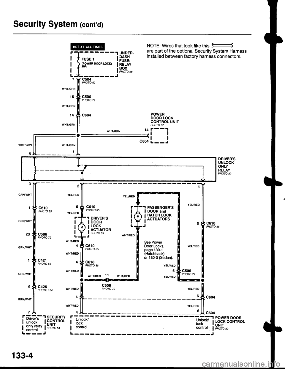
Security System (cont'd)
NOTE: Wires that look like this 5--------J
are part of the optional Security System Harness
WHT/GRN
6
r-l-------1 qrygER- l:Ii:"J u'e vPuv"q' vcvu"rv evole"' ' 'o
I I rus. t i P$38 installed between factory harness connectors'
! l s3*"0*"-* !83f"I I I aoros|LJ-------J, Y9,':A,,,rnr,o"n Iurs I csoe
I PHOfO 79
wnicnr I
r+ f, coor B38"tTo"*II CONTNOL UNITwHr GRN ll PHA|O 82
ll ,n",io"u 11i--l
ll--il-L__J
ll """o"n ll
A_______t_A
DRIVER'SUNLOCKONLYRELAYPHO|O 82
GFNAAIHT
GBNAVHT
GFNrI/VHT
GRNAiVHT
GRNAVHT
:4
;-[
@a
85
79
56
124ll n-o
l1
PASSENGER'SDOOR andHATCH LOCKACTUATORS
Seo PowerDoor Locks,page l3G1(Hatchback)or 1sGg (Sodan).
c610
VEL/BED
6
YEVREO
r ii.#:,:.'r sEcuRrw r;-_=----- ----=:-.r powER DooR
| ilril'ir- | fi$,ynol I unrucn/ l:nl@v I Lo.cK coNrRoL
| ::1ffi1"v l;;6ib" I contror controt liri6'ibazL---J L------- _____J
133-4
Page 1554 of 1681
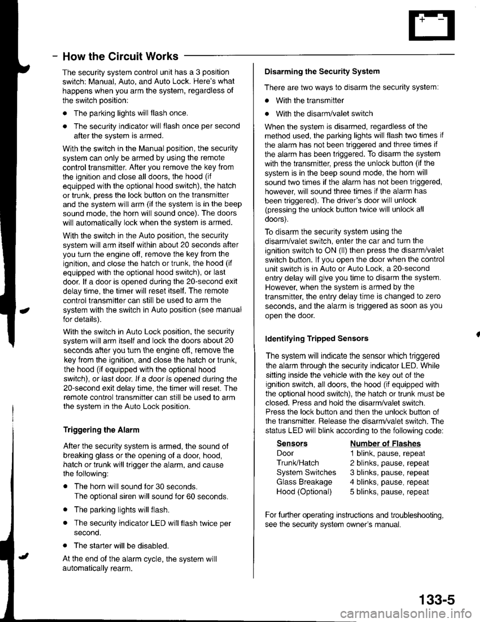
- How the Circuit Works
The security system control unit has a 3 position
switch: Manual. Auto. and Auto Lock. Here's what
happens when you arm the system, regardless ol
the switch position:
o The parking lights will flash once.
. The security indicator will flash once per second
after the system is armed.
With the switch in the Manual position, the security
system can only be armed by using the remote
control transmitter, After you remove the key from
the ignition and close all doors, the hood (if
equipped with the optional hood switch), the hatch
or trunk. Dress the lock button on the transmitter
and the system will arm (if the system is in the beep
sound mode, the horn will sound once). The doors
will automatically lock when the system is armed.
With the switch in the Auto position, the security
system will arm itself within about 20 seconds after
you turn the engine off, remove the key from the
ignition, and close the halch or trunk, the hood (if
equipped with the optional hood switch), or last
door. lf a door is opened during the 2o-second exit
delay time, the timer will reset itself . The remote
control transmitler can still be used to arm the
system with the switch in Auto position (see manual
for details).
With the switch in Auto Lock position, the security
system will arm itself and lock the doors about 20
seconds after you turn the engine of{, remove the
key from the ignition, and close the hatch or trunk,
the hood (if equipped with the optional hood
switch), or last door. lf a door is opened during the
2o-second exit delay time, the timer will reset. The
remote control transmitter can still be used to arm
the system in the Auto Lock position.
Triggering the Alarm
After the security system is armed, the sound ot
breaking glass or the opening of a door, hood,
hatch or trunk will trigger the alarm, and cause
the following:
r The horn will sound for30 seconds.
The optional siren will sound lor 60 seconds.
. The parking lights will flash.
. The security indicator LED will flash twice per
second.
. The starter will be disabled.
At the end of the alarm cycle, the system will
automatically rearm.
Disarming the Security System
There are two ways to disarm the security system:
. With the transmitter
o With the disarm/valet switch
When the system is disarmed, regardless of the
method used, the parking lights will flash two times if
the alarm has not been triggered and three times if
the alarm has been triggered. To disarm the system
with the transmitter, press the unlock button (if the
system is in the beep sound mode, the horn will
sound two times if the alarm has not been triggered,
however, will sound three times if the alarm has
been triggered). The driver's door will unlock
(pressing the unlock button twice will unlock all
doors).
To disarm the security system using the
disarm/valet switch, enter the car and turn the
ignition switch to ON (ll) then press the disarm/valet
switch button. lf you open the door when the control
unit switch is in Auto or Auto Lock, a 2o-second
entry delay will give you time to disarm the system.
However, when the system is armed by the
transmitter, the entry delay time is changed to zero
seconds, and the alarm is triggered as soon as you
oDen the door.
ldentifying Tripped Sensors
The system will indicate the sensor which triggered
the alarm through the security indicator LED. While
sitting inside the vehicle wlth the key out of the
ignition switch, all doors, the hood (if equipped with
the optional hood swilch), the hatch or trunk must be
closed. Press and hold the disarm/valet switch.
Press the lock button and then the unlock button of
the transmitter. Belease the disarm/valet switch. The
status LED will blink according to the following code:
Sensors
Door
Trunk/Hatch
System Switches
Glass Breakage
Hood (Optional)
Number ol Flashes
1 blink, pause, repeat
2 blinks, pause, repeat
3 blinks, pause, repeat
4 blinks, pause, repeat
5 blinks, pause, repeat
For further operating instructions and troubleshooting,
see the security system owner's manual.
133-5
Page 1555 of 1681
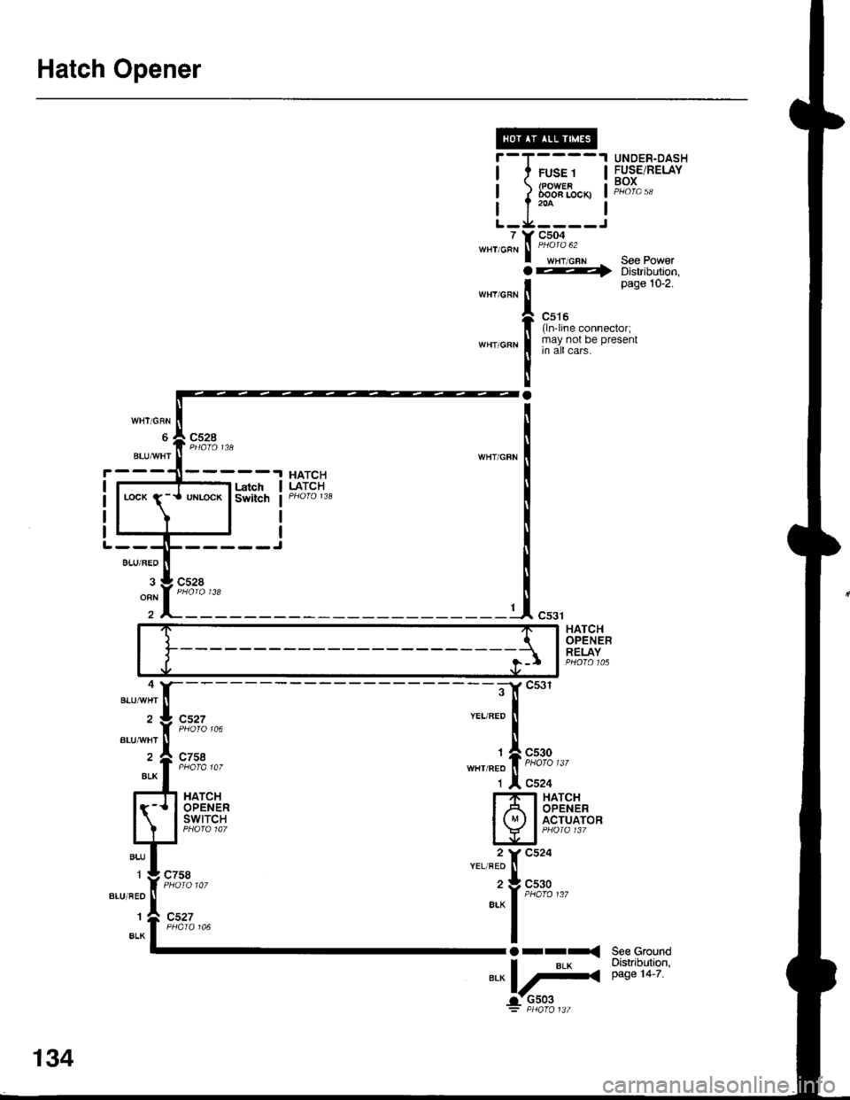
Hatch Opener
7WHT/GRN
WHY/GRN
;il
T(
t
IY
Ia
I
a
FUSE 1(POWERDooa Locx)
c504
wHT,cFN See Power---r> Distribution,page 10-2.
c516(ln'line connector;may not be presentin all cars.
UNDER-DASHFUSE/RELAYBOX
See GroundDistribution,page 14-7.
cs27
c758
c758
BLUAA/HT
cs30
c524HATCHOPENERswtTcH
HATCHOPENERACTUATOR
"":il;;,,,
Orr-<
*"L#
BLUAA/HT
134
Page 1556 of 1681
![HONDA INTEGRA 1998 4.G Workshop Manual lnterlock System
- 98-99 Models
l
HxPS*. !Til;;----
-i yxRi*I DASH I / rulE rz I HOOD
i[EiF,, i]!orn.o" Bli;;1il ilEjii
!s?T"., Lt::-s::3L j "3T",,. P,vu,d Lg _ _ Lt av ^rra: 8Y C216 16I wx HONDA INTEGRA 1998 4.G Workshop Manual lnterlock System
- 98-99 Models
l
HxPS*. !Til;;----
-i yxRi*I DASH I / rulE rz I HOOD
i[EiF,, i]!orn.o" Bli;;1il ilEjii
!s?T"., Lt::-s::3L j "3T",,. P,vu,d Lg _ _ Lt av ^rra: 8Y C216 16I wx](/img/13/6069/w960_6069-1555.png)
lnterlock System
- '98-'99 Models
'l
HxPS*. !'Til;;----
-''i yxRi*I DASH I / rulE rz I HOOD
i[EiF,, i]!orn.'o" Bli;;1il ilEjii
!s?T"., Lt::-s::3L j "'3T",,. P,v'u,d Lg _ _ Lt av ^rra: 8Y C216 16I wxlcnr,r PHora 24
J!^_YEUBLI
UNOER.OASHFUSE/RELAYBOX
c440
c432
ll S€o Power Diskibution,I page 10-9.
,n"tto"" I
1c,u'"" 11 | sa31F-I''I BRAKE SWITCH T--1 THROTTLE
I I closed wrth brake | 5"ns6, I lg.qLrlgN fiP)
lq-]J 1"""",i:;*""* t iii*' i "s'H39*
:ilH1fti$;",,"
;lX *Tt r#i*f= ft;1uii,'" 11? I ;:: [S[l 5p,[,"f*,,*""*l
;ny,t;sfl E?[T
l-T;l'"
t, L- t''""t'1"' ---C "0.,, to"-t' I
STEEBINGLOCK
r-=KeyInlerlockSwitchClosed withkey pushsd.
KeylnterlockSolenold
'" I--j"$t'U"t--:t "o', 3*".''
'f 'o"
i
-
r-, gEr-
- - -;;; - - - -: t rmrsu tsstot't ll
L$'e: 1ui ifiin?rri!::::
I
:- - _ _ _ _::{ : _ _ _ _ _ _ __ - - - J "",.
-JWHT]"TEL
INTERLOCKCONTROLUNIT
;,-".t^-l[-
-------;;f[ ":'"'"."'
seeA/rGearr A c+sg ar< Posnon
wHr BL( [ ero'o i28 cn1,,rvxr ll Indicalor
r* "o"* rz | g+r.q -,
l,/ |Bi*:yJL,tx o"nf'$y:-----1a"r.EAR
I G-11 sh,ft rever push ! | "- i a.o, I P/,oSlTloN swlTcH
-il,tii,oJ,tu"o.""""0 | ^ll \, | -'
-iJcni.'
!"L-----. i, !
'g",J"T,F;:'A$l"Y"";%,r, i" ---1 'r a solenord flom enelgrTing
"'^l '";;'"-
R:":.Rt?i# i F 33""'?Ji"" i ::f;',3J3u:"00":"":Ji",",",a-< 3l'Jlilgl L___+_::':_j ;;ff;;;;rr"p,".."dBLK I NOTE: In case olBLK I NOTE: In case ot syslem
Y r ! ccro malfunchon lhesh1fllever
I ",, I paoro to can be released byI --' I oushino the ionition kev
J---r"?r-"*l-f----) Distribution,
I oaoe to-o.
I ruse aa flNTERLocK uNrn( r.5^
i.- - ---- -
Koy Int6rlockCircuitAllows key inlerlocksolenoid to boenergized unlessshift lever is in "P'
138
f __ --__l pushing lhe ignition key
,lt--- il'""J1:oi:'""i,:"0'"d'l-' c4ol
Page 1557 of 1681
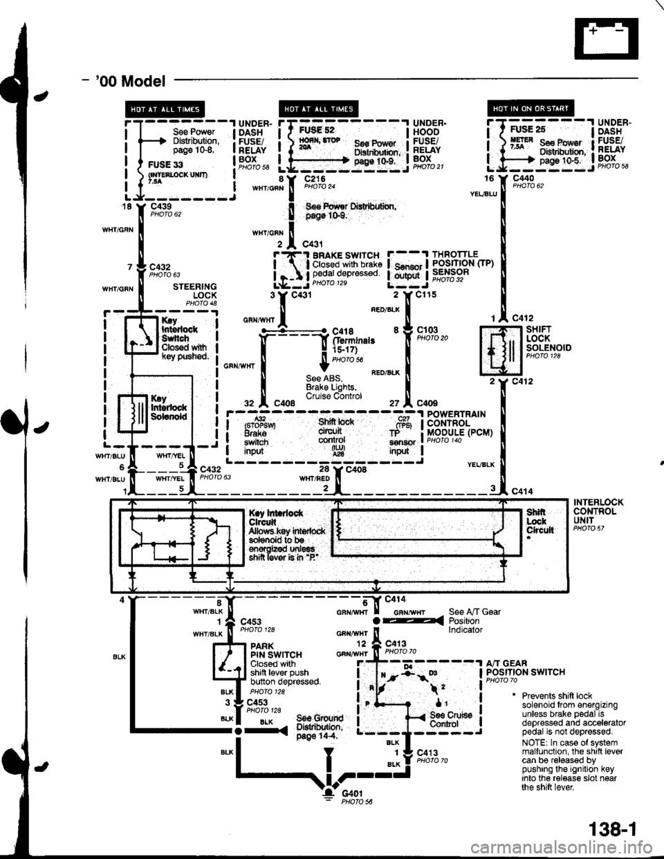
- '00 Model
I
I
FUsg 52I56€ Pow€r Ilxrtdhxbn, :g9:t"t:.i
UNDER.HOODFUSEiRELAYBOXPHOfO 21
Sse Power I DASHDlslribution, : FUSE/page 1G8. I RELAY
c440
c432
WHT/GFNSTEERINGLOCK
rry Ihtsdock :Suhch IClos€d with Il(ey pusned. I
I
I
I
I
I
I
c432
It
I
I
l-
WrtT/BLU
WHT/BLU
KryIr$rdockSdanold
c412-l SHIFT
, I LOCKI I SOLENOIDI lcuoto tzo
Jc412
c414
rAc4
m2Y c4
INtl
.-, I
i/BLX U
-rl"o
POWERTRAINCONTROLMODULE(PCM)
YEVBLX
INTERLOCKCONTROLUNIT
"-*;.'l[-
- - - - - - - -;*f-tr "'"'"'"-,,
r I casr a4
""""#"J;:.
_^ ll"ij*sa*,"
l4J $l't'"ii,''F:^,
*"T't. 3il1;'
;fi;ifJ,t""**o
i"'f- .
*1'
S€e A,/T GsarPositionlndicator
"liiffo,,' a"-BLK I 506 Grourd I-i-. ;*'o' ---;
*"1
I "l! s'*l'"-
Prevents shift locksolenoid trom energizingunless brake pedal isdepressed and acceleratorpedal is not depressed.
NOTE| In case of systemmalfunction, the shilt levercan be released bypushing the ignition keyinto the release slot nearthe shift lever
$l;---l UiSi'"
BRAKE SWITCH F--.t THROTTLE
;'3i:g*s::: !.mnj iffibr-
*,
,V-I'c4ol: PHoro s6
138-1
Page 1558 of 1681
lnterlock System
- How the Circuit Works
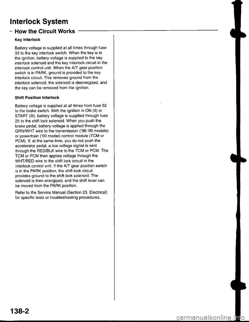
Key Interlock
Battery voltage is supplied at all times through f use
33 to the key interlock switch. When the key is in
the ignition, battery voltage is supplied to the key
intedock solenoid and the key interlock circuit in the
interlock control unit. When the A/T gear position
switch is in PABK, ground is provided to the key
interlock circuit. This removes ground from the
interlock solenoid, the solenoid is deenergized, and
the key can be removed from the ignition.
Shift Position Interlock
Battery voltage is supplied at all times lrom fuse 52
to the brake switch. With the ignition in ON (ll) or
START (lll), battery voltage is supplied through luse
25 to the shift lock solenoid. When you push the
brake pedal, battery voltage is applied through the
GRN/VVHT wire to the transmission ('98-�99 models)
or powertrain ('00 model) control module (TCM or
PCM). lf, at the same time, you do not push the
accelerator pedal, a low voltage signal is sent
through the RED/BLK wire to the TCM or PCM. The
TCM or PCM then applies voltage through the
WHT/RED wire to the shift lock circuit in the
interlock control unit. lf the A,/T gear position switch
is in the PARK position, the shift lock circuit
provides ground to the shift lock solenoid. The
solenoid is then energized, and the shift lever can
be moved from the PARK Dosition.
Refer to the Service Manual (Section 23, Electrical)
for specific tests or troubleshooting procedures.
138-2
Page 1559 of 1681
Power Mirrors
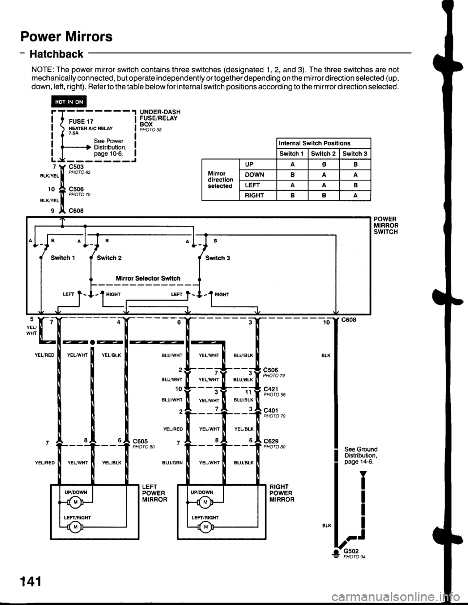
- Hatchback
NOTE: The power mirror switch contains three switches (designated 1, 2, and 3). The three switches are not
mechanically connected, but operate independently ortogether depending on the mirror direction selected (up,
down,left, right). Refertothetable belowfor internalswitch positions according to the mirrror direction selected.
@
I I ruse rz I
I xearenrceeuv I
|{754 |I I Uee FOI/ver I! l-----.-.| Distribution. !I I pase 10-6. ILg-------J
UNDER.DASHFUSE/RELAYBOX
7 ll, Cs03
"'-^."..
|
"'otou'
'o ft ffi%,,erxner II x c608
Internal Switch Positlons
Switch 'lSwltch 2Switch 3
Mirordirectionselected
UPAB
oowNA
LEFTAAE
RIGHTBA
B
Swiich 3
Mirror Ssl3clor Switch
LEFT } - I.1 RIGIfI
POWERMIRRORswtTcH
BLU/'WHT
BLU]'IVHI
10
BLU^^/HT
YEL/REO
7
ALU/GRN
YEL/YVHTBLU/ALK
11BLU/BLK
cs06
7
YEL,ryvHTPHOTO 56
c401
c629PHO|O A0c605PHOTA 80
141
Page 1560 of 1681
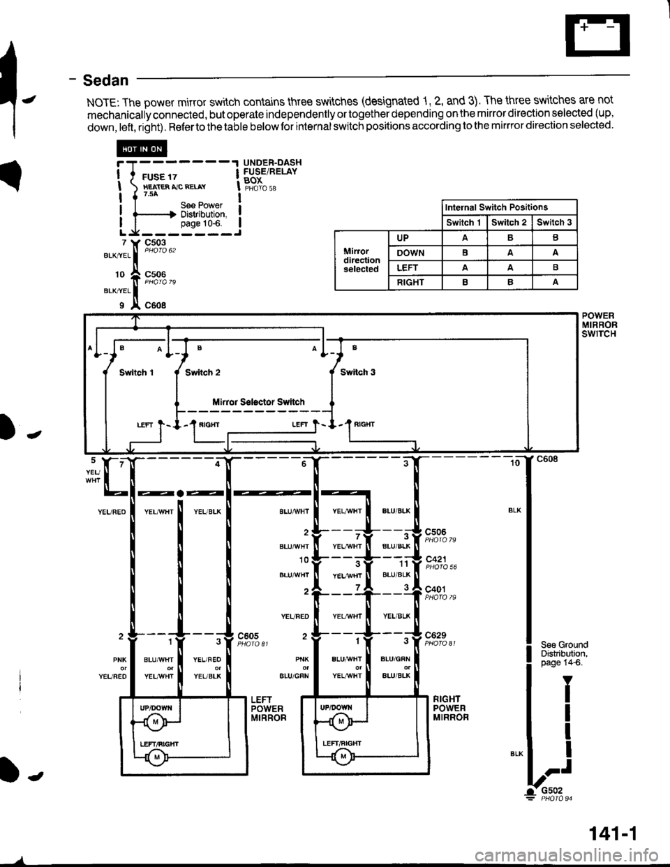
- Sedan
NOTE: The power mirror switch contains three switches (designated 1, 2, and 3). The three switches are not
mechanically connected, but operate independently or together depending on the mirror direction selected (up,
down,left, right). Refertothetable belowfor internalswitch positions according to the mirrror direction selected.
c506
c421
c401
BLU/GRN
ALU/BLK
3
YEL/VI/HT
1
B!U/{VHI
c629
I
POWERMIRRORswrTcH
YEU
BLU/BLK
11BLU/BLK
BLUA/VHI
BLUA!/HT
10
YEURED
2c6053
YEL/FEO
YEUBLK
1
BLUA!/HT
YELI/VHT
PNK
YEUFEOBIU/GFN
RIGHTPOWERMIRROR
f-
Inlehal Switch Positions
Switch 1Switch 2Switch 3
Miriordirectionselected
UPAB
DOWNBAA
LEFTAA
RIGHTBA
@
7 Y c503
".*.. |
""oto u'
'o + "";%,,erxrer II x c6o8
Switch 3
'1"'"-_LEFT }- I.'I fiIGXT
B
Mirror S€loctor Ssttch
141-1
/