engine HONDA INTEGRA 1998 4.G Workshop Manual
[x] Cancel search | Manufacturer: HONDA, Model Year: 1998, Model line: INTEGRA, Model: HONDA INTEGRA 1998 4.GPages: 1681, PDF Size: 54.22 MB
Page 353 of 1681
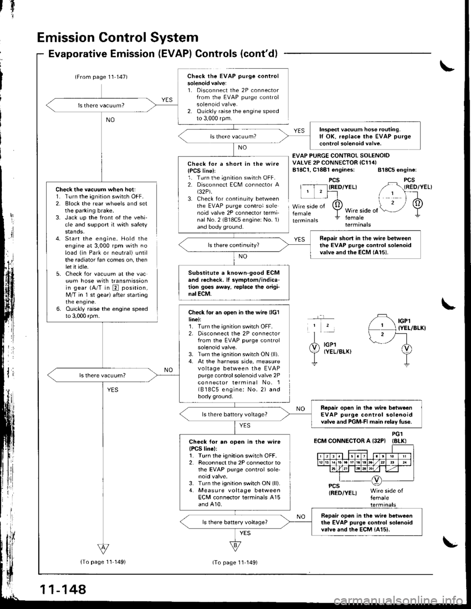
Emission Control System
Check the vacuum when hot:1. Turn the ignition switch OFF.2. Block the rear wheels and setthe parking brake.3. Jack up the front of the vehi-cle and support it with safetystands.4- Start the engine. Hold theengine at 3,000 rpm with noload (in Park or neutral) untilthe radiator fan comes on, thenlet it idle.5. Check for vacuum at the vacuum hose with transmissionin gear (A/T in E position,M/T in 'l st gear) after startingrne engrne.6. Ouickly raise the engine speedto 3,000 rpm.
Evaporative Emission (EVAP) Controls (cont'd)
(From page 1'l 147)Check the EVAP purge controlsolenoid valve:1. Disconnect the 2P connectorfrom the EVAP purge controlsolenoid valve.2. Ouickly raise the engine speedto 3,000 rpm.
{To page 11 149)
tfl'I
Check lor a short in the wire{PCS line}l1. Turn the ignition switch OFF.2. Disconnect ECM connector A(32P).
3. Check for continuity betweenthe EVAP purge control solenoid valve 2P connector termi-nal No. 2 (818C5 engine: No. 1)and body ground.
Check for an open in the wire llclline):1. Turn the ignition switch OFF.2, Disconnect the 2P connectorfrom the EVAP purge controlsolenoid valve.3. Turn the ignition switch ON (ll).
4. At the harness side, measurevo ltage between the EVAPpurge controlsolenoid valve 2Pco n nector terminal No. 1( B 18C5 engine: No. 2) andbody ground.
EVAP PURGE CONTROI SOLENOIDVALVE 2P CONNECTOR IC114)B18C1, Cl8Bl engines: 818C5 engine:
PCSIRED/YEL}
femaleWire side offemaleterminals
YES
IGPl{YEL/BLKI
IGPlIYEL/BLKI
ECM CONNECTOR A {32PIPG1IBLKI
Insp€ct vacuum hose routing.lf OK, replace the EVAP purge
control solenoid valve.
neDair short in the wire betweenthe EVAP purge control solenoidvalve and the ECM lAl5).
Substitute a known-90od ECMand recheck. lI symptom/indica-tion goes away, replace the origi-nal ECM.
Repair open in the wirc betweenEVAP purge control solenoidvalve and PGM-FI main relav fuse.ls there battery voltage?
Check for an open in the wireIPCS linel:1. Turn the ignition switch OFF.2. Reconnect the 2P connector tothe EVAP purge control sole'noid valve.3. Turn the ignition switch ON (ll).
4. Measure voltage betweenECM connector terminals A15and A10.
Bopair open in the wiro betweenthe EVAP purgo control 3olanoidvalvo and the EcM {415).
11-144
(To page 11-149)
Page 354 of 1681
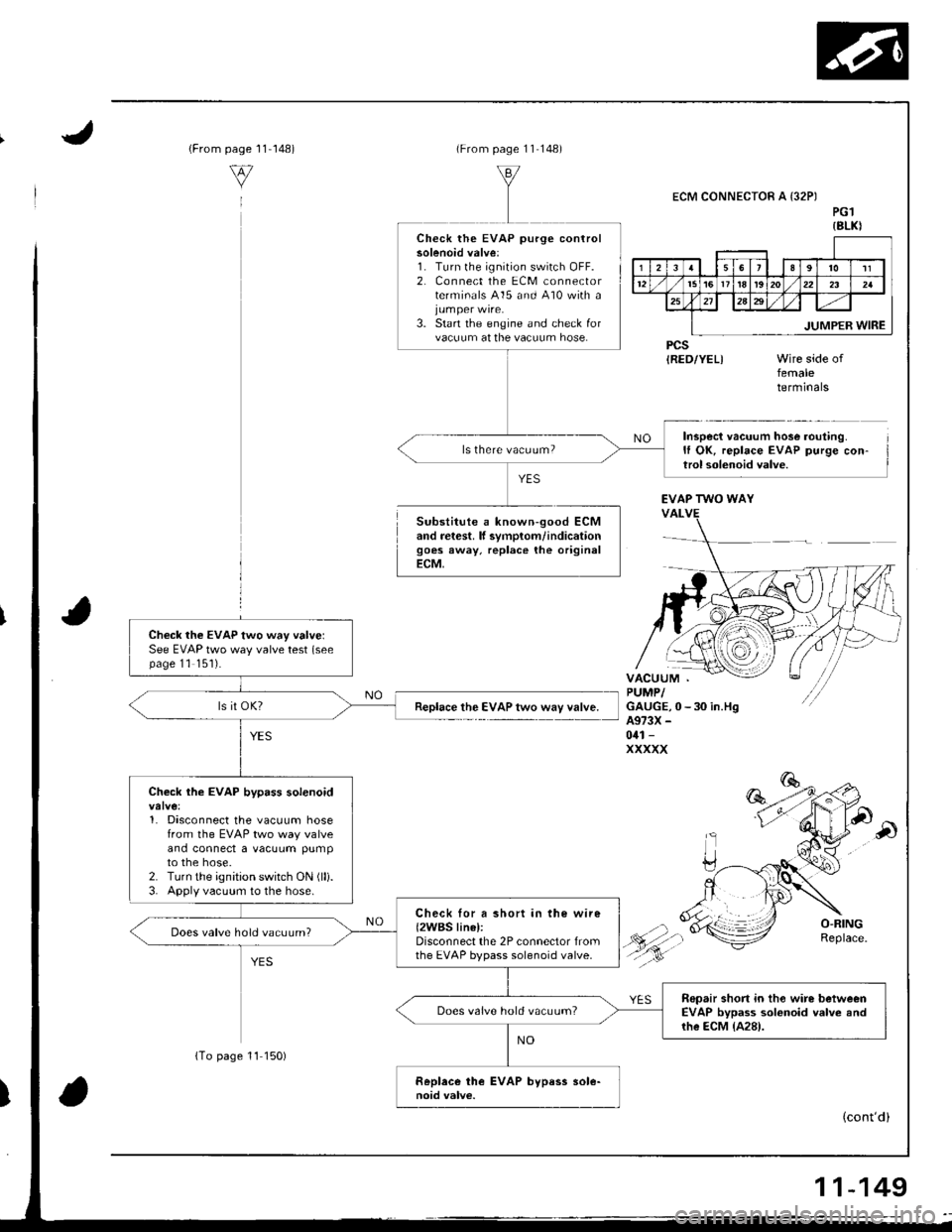
{From1 1-148)page
v
(From page 11 148)
Substitute a known-good ECMand retest. lf svmplom/indicationgoes away, replace the originalECM,
ECM CONNECTOR A {32PIPG1{8LKI
PCSIRED/YEL)femaletermrnars
Inspect vacuum hose routing.It OK, replace EVAP purge con-trol solenoid valve.
Check the EVAP purge controlsolenoid valve:1. Turn lhe ignition switch OFF.2, Connect the ECM connectorterminals 415 and 410 with a
3. Start the engine and check forvacuum at the vacuum hose.
ls there vacuum?
EVAP TWO WAY
Check the EVAP two way valvelSee EVAP two way valve test (seepage 11 '151).
Replace the EVAP two way valve.
Check the EVAP bypass solenoid
1. Disconnect the vacuum hosefrom the EVAP two way valveand connect a vacuum pumpto the hose.2. Turn the ignition switch ON (lli.
3. Apply vacuum to the hose.
Check lor a short in the wire{2WBS linel:Disconnect the 2P connector fromthe EVAP bypass solenoid valve.
Does valve hold vacuum?
Repair short in tho wire betweenEVAP bypass solonoid valve andrhe ECM {A28).
Does valve hold vacuum?
(cont'd)
{To page 11 150)
11-149
Page 357 of 1681
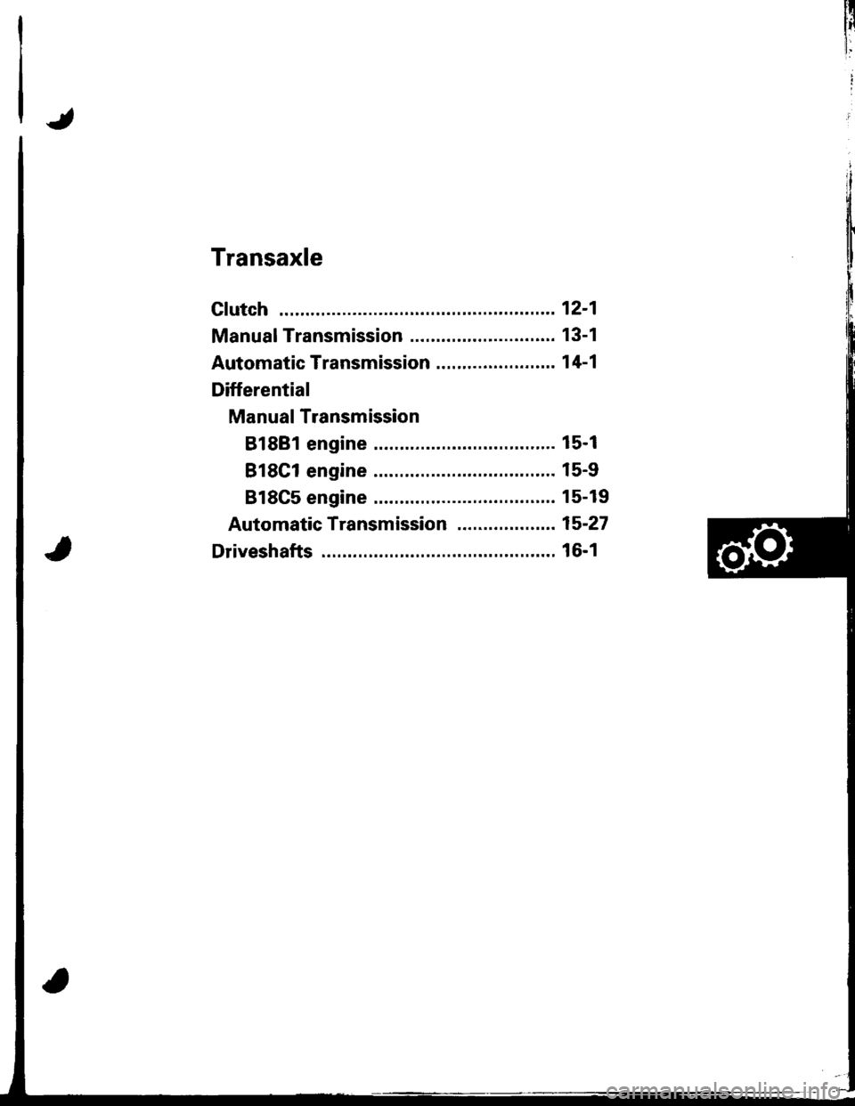
Transaxle
Clutch ...........12-1
Manual Transmission ............................ 13-1
Automatic Transmission ....................... 1 4-1
Differential
Manual Transmission
B1881 engine ................................... 15-1
818C1 engine ................................... 15-9
B18C5 engine .............. 15-19
Automatic Transmission ................. .. 15-27
Driveshafts ... 16-1
Page 361 of 1681
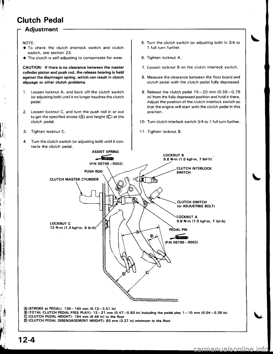
Clutch Pedal
Adjustment
NOTE:
a To check the clutch interlock switch and clutch
switch, see section 23.
a The clutch is self-adjusting to compensate Ior wear.
CAUTION: ll there is no clealance between the master
cylinder piston and push rod, the release bearing is held
against the diaphragm spring, which can result in clutch
slippage or other clutch problems.
1. Loosen locknut A, and back off the clutch switch
(or adjusting bolt) until it no longer touches the clutch
peoal.
2. Loosen locknut C. and turn the push rod in or out
to get the specified stroke (@) and height {O) at the
clutch Dedal.
3. Tighten locknut C.
4. Turn the clutch switch (or adjusting bolt) until it con-
tacts the clutch pedal.
ASSIST SPRING
@{
{PiN 08798-9002t
(STROKE at PEDAL): 130-140 mm (5.12-5.51 in){TOTAL CLUTCH PEDAI- FREE PLAYI: 12-21 mm (0.47-0.83 inl including tho p6dal play{CLUTCH PEDAL HEIGHT): 164 mm 16.46 inl to the tloor(CLUTCH PEDAL DISENGAGEMENT HEIGHTI: 83 mm {3.27 inl minimum to the floo.
t?
5.Turn the clutch switch (or adjusring bolt) in 3/4 to
1 full turn further.
Tighten locknut A.
Loosen locknut B on the clutch interlock switch.
Measure the clearance between the floor board and
clutch pedal with the clutch pedal tully depressed.
Release the clutch pedal 15-20 mm (O.59-O.79
in) from the fully depressed position and hold it there.
Adjust the position of the clutch interlock switch so
that the engine will stan with the clutch pedal in this
position.
Turn clutch interlock switch 3/4 to 1 full turn further.
Tighten locknut B.
9.
6.
7.
8.
10.
11.
LOCKNUT B9.8 N.m 11.0 kgt.m, 7 lbl.ft)
CLUTCH INTERLOCKswrTcHPUSH ROD
CLUTCH MASTER CYLINDER
CLUTCH SWITCH(or AOJUSTING BOLT)
LOCKNUT A9.8 N.m (1.0 kgf.m, 7 lbt.frl
l
{P/N 0879a-9002)
12-4
1- 10 mm (0.O4-O.39 inl
Page 366 of 1681
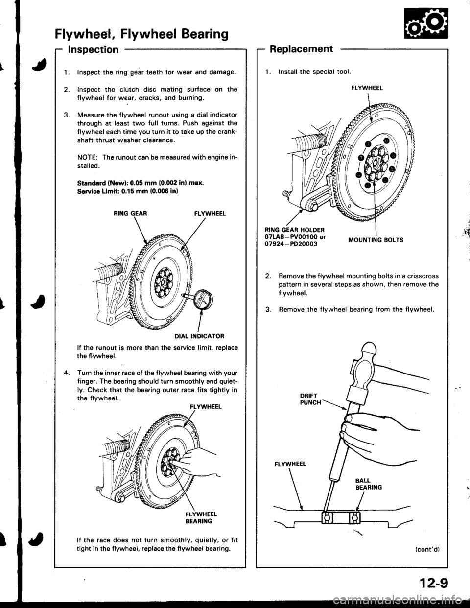
Flywheel, Flywheel Bearing
Inspection
t
',4
i
Replacement
1. Install the special tool.
MOUNTING BOLTS
Remove the flywheel mounting bolts in a crisscrosspattern in several steps as shown, then.emove the
Jlvwheel.
Bemove the flywheel bearing from the flywheel.
(cont'd)
FLYWHEEL
I
1.Inspect the ring gear teeth tor wear and damage.
Inspect the clutch disc mating surtace on the
flywheel for wear, cracks, and burning.
l\,reasure the flywheel runout using a dial indicator
through at least two full turns. Push agsinst the
Jlywheel each time you turn it to take up the crank-
shatt thrust washer clearance.
NOTE: The runout can ba measured with engine in-
stalled.
SiEndrrd (Ncw): 0.05 mm (0.002 inl max.
SerYicc Llmh: 0.15 mm (0.006 inl
DIAL INOICATOR
lf the runout is more than the service limit, reolace
the flywheel.
Turn the inner race of the flywheel bearing with your
tinger. The bearing should turn smoothly and quiet-
ly. Check that the bearing outer race tits tightly in
the flvwheel.
FLYWHEELBEARING
lf the race does not turn smoothly, quietly, or tit
tight in the flywheel, replace the flywheel bearing.
4.
FLYWHEEL
12-9
Page 372 of 1681
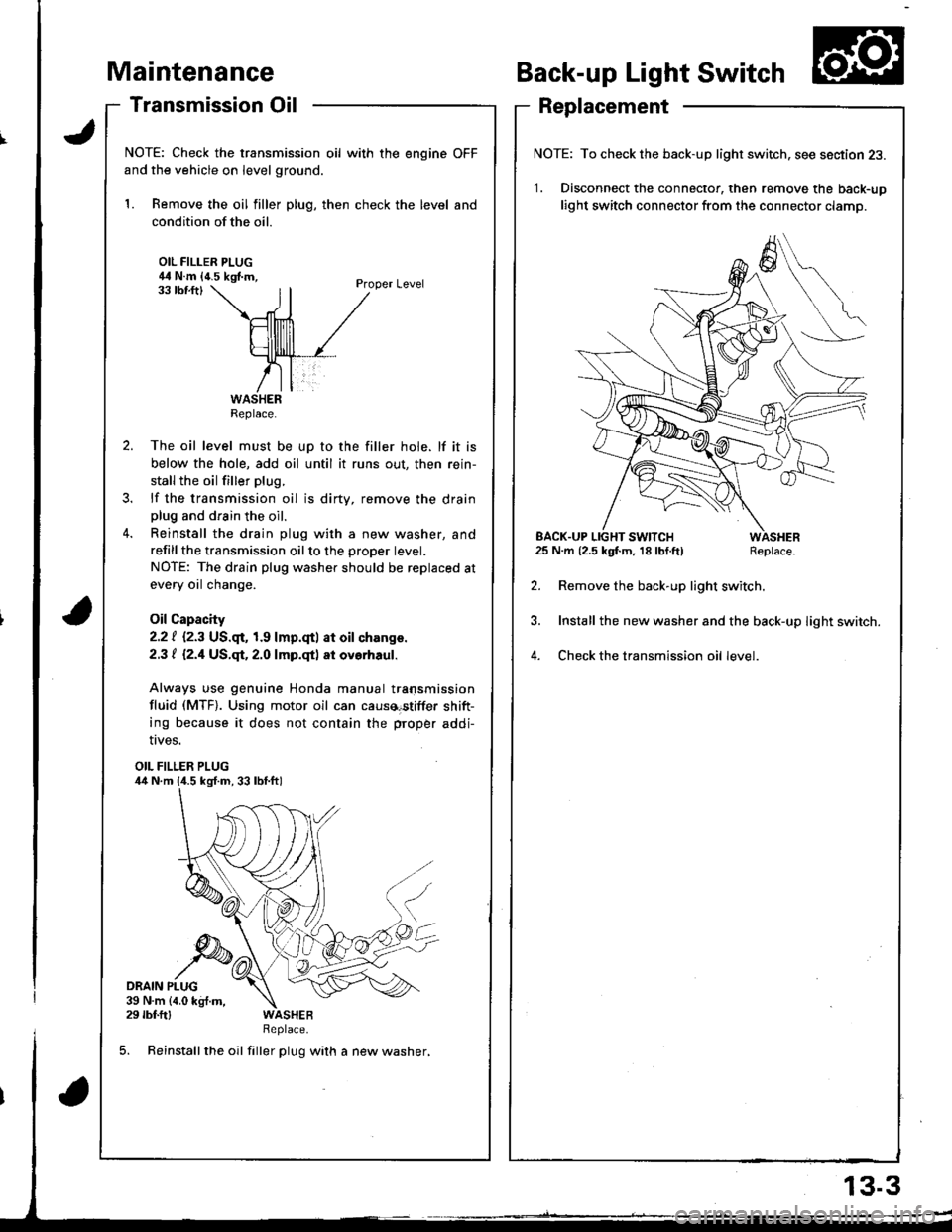
aintenance
Transmission Oil
NOTE: Check the transmission oil with the engine OFF
and the vehicle on level ground.
1. Remove the oil filler plug, then check the level and
condition of the oil.
OIL FILLER PLUG44 N.m {4.5 kgf.m,Proper Level33 tbf.ftl
The oil level must be up to the filler hole. lf it is
below the hole, add oil until it runs out, then rein-
stall the oil filler plug.
lf the transmission oil is dirty, remove the drainplug and drain the oil.
Reinstall the drain plug with a new washer, and
refillthe transmission oilto the proper tevet.
NOTE: The drain plug washer should be replaced at
every oil change.
Oil Capacity
2.2 | i.2.3 US.qr,1.9 lmp.qtl at oil ch.nge.
2.3 t l2.1US.qt,2.O lmp.qtl at ovorhaul.
Always use genuine Honda manual transmission
fluid (MTF). Using motor oil can causa€tiffer shift-
ing because it does not contain the proper addi-
Back-up Light Switch
Replacement
NOTE: To check the back-up light switch. see section 23.
1. Disconnect the connector, then remove the back-up
light switch connector from the connector clamp.
l.m {2.5 kgf.m, 18lbf.ft) Replace.
Remove the back-up light switch.
Install the new washer and the back-up light switch.
Check the transmission oil level.
!ves.
OIL FILLER PLUG
DRAIN PLUG39 N.m {4.0 kg{.m,29 rbf.ftlReplace.
5. Reinstall the oil filler plug with a new washer,
Replace.
EACK.UP LIGHT SWITCH25 N.m {2.5 kgf.m, 18 lbf.ft)
13.3
Page 374 of 1681
I
T
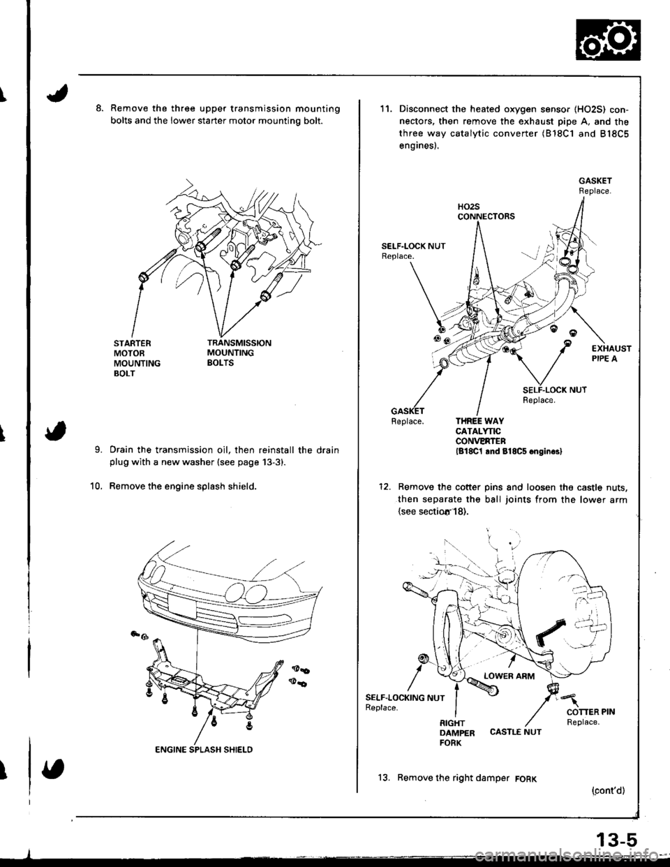
Remove the three upper transmission mounting
bolts and the lower starter motor mountino bolt.
STARTERMOTOEMOUNTINGBOLT
Drain the transmission oil, then reinstall the drainplug with a new washer (see page 13-3).
Remove the engine splash shield.10.
11.
6tr!
/
SELF.LOC1(ING NUTReplace.
Disconnect the heated oxygen sensor (HO2S) con-
nectors, then remove the exhaust pipe A. and the
three way catalytic converter (B'18C1 and B18C5
engines).
Feplace. THREE WAYCATALYNCCONVERTENlg18C1 lnd 818C5 onginrsl
Remove the cotter pins and loosen the castle nuts,
then separate the ball joints from the lower arm(see sectiotr'l8).
LOWER ARM
DAMPER CASTLE NUTFORK
13. Remove the right damper FORK
(cont'd)
13-5
Page 375 of 1681
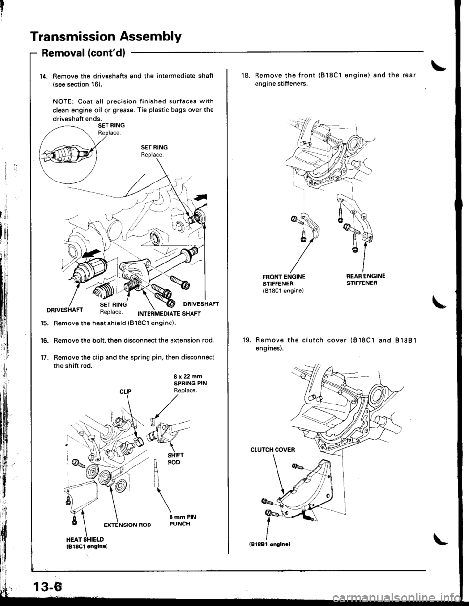
Transmission Assembly
Removal (cont'dl
14. Remove the driveshafts and the intermediate shaft
(see section 16).
NOTE: Coat all precision finished surfaces with
clean engine oil or grease. Tie plastic bags over the
driveshaft ends.
SET RINGBeplace.
DRIVESHAFTDRIVESHAFT Replace. trweinnro,ora ""ot
15. Remove the heat shield (Bl8c1 engine).
16. Remove the bolt, then disconnect the extension rod.
17. Remove the clip and the spring pin, then disconnect
the shift rod.
8x22mmSPRING PIN
CLIP Replace
fl noo
flil
\
I mm PINPUNCH
(818c1 .ngin.l
13-6
'18. Remove the front (Bl8C1 engine) and the rear
engine stiffeners,
REAR ENGINESTIFFENER
Remove the clutch cover {818C1 and 81881
enganes),
{B188l .ngin.}
Page 376 of 1681
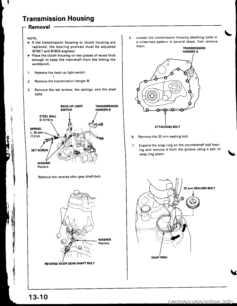
Transmission Housing
Removal
NOTE:
. lf tho transmission housing or clutch housing are
replaced, the bearing preload must be adjusted
(818C1 8nd 818C5 engines).
. Place the clutch housing on two pieces of wood thick
enough to keep the mainshaft from the hifting the
workbench.
1. Remove the back-up light switch.\
2. Remove the transmission hanger B.
3. Remove the set screws, the springs, and the steel
balls.
BACK-UP LIGHTswrTcHTRANSMISSIONHANGER B
STEEL BALLD. 5/16 in
SET SCREW
WASHERReplace.
Remove the reverse idler gear shaft bolt.
13-10
5. Loosen the transmission housing attaching bolts in
a crisscross pattern in several steps, then remove
them.TRANSMISSION
Remove the 32 mm sealing bolt.
Expand the snap ring on the countershaft ball bear-
ing and remove it from the groove using a pair of
snap ring pliers.
6.
7.
ATTACHING BOLT
SNAP RING
32 mm SEALING BoLT
Page 388 of 1681
|'I
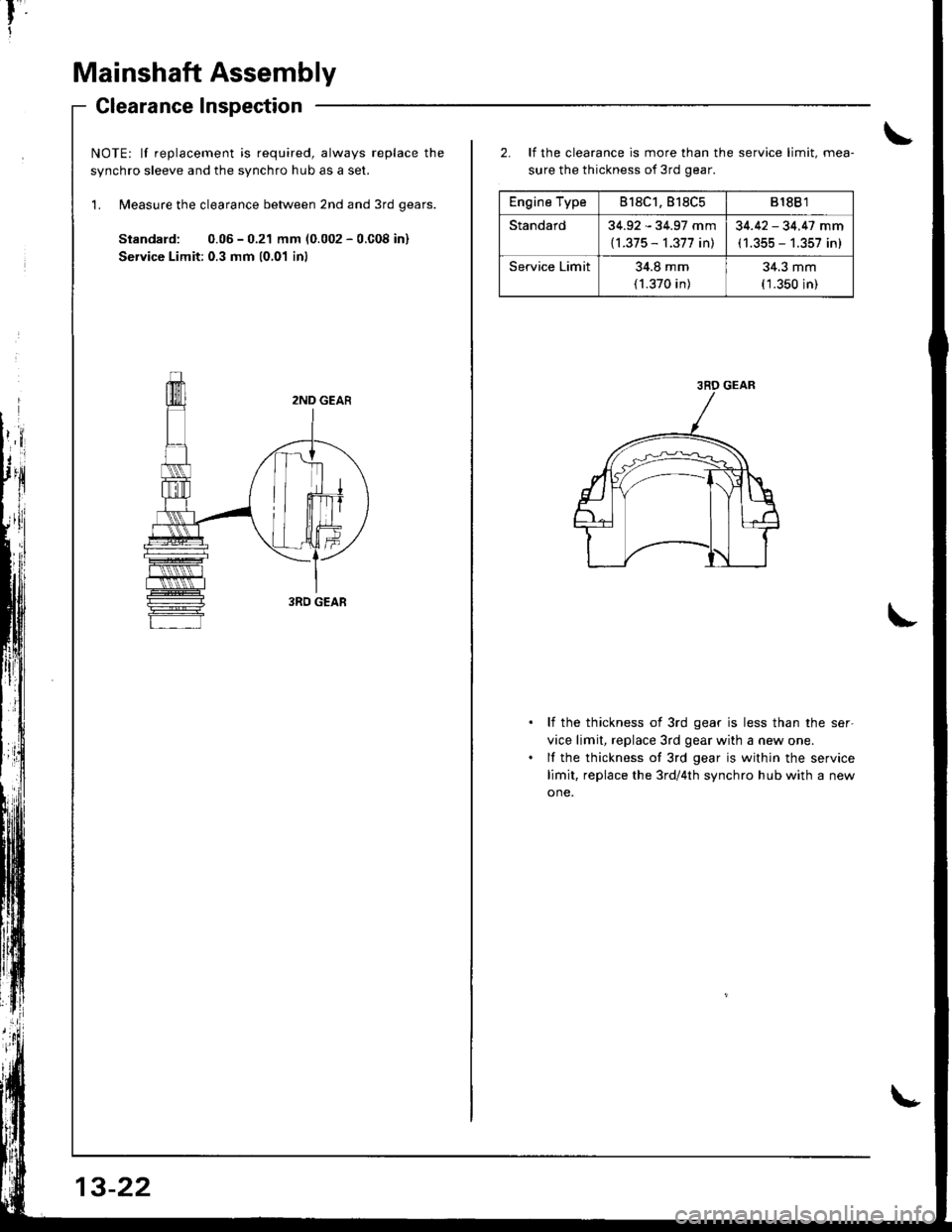
Mainshaft Assembly
Glearance Inspection
NOTE: lf replacement is required, always replace the
svnchro sleeve and the svnchro hub as a set.
'L Measure the clearance between 2nd and 3rd qears.
Standard: 0.05 - 0.21 mm (0.002 - 0.C08 in)
Service Limit: 0.3 mm 10,01 inl
13-22
Engine Type818C1.818C5818B 1
Standard34.92 - 34.97 mm
{l.375 - 1.377 in)
34.42 - 34.47 mm(1.355 - 1.357 in)
Service Limit34.8 mm
(1.370 in)
34.3 mm(1.350 in)
2. It the clearance is more than the service limit, mea-
sure the thickness of 3rd gear.
li the thickness of 3rd gear is less than the ser-
vice limit, replace 3rd gear with a new one.
lf the thickness of 3rd gear is within the service
limit, replace the 3rd/4th synchro hub with a new
one.
3RD GEAR