engine HONDA INTEGRA 1998 4.G Workshop Manual
[x] Cancel search | Manufacturer: HONDA, Model Year: 1998, Model line: INTEGRA, Model: HONDA INTEGRA 1998 4.GPages: 1681, PDF Size: 54.22 MB
Page 510 of 1681
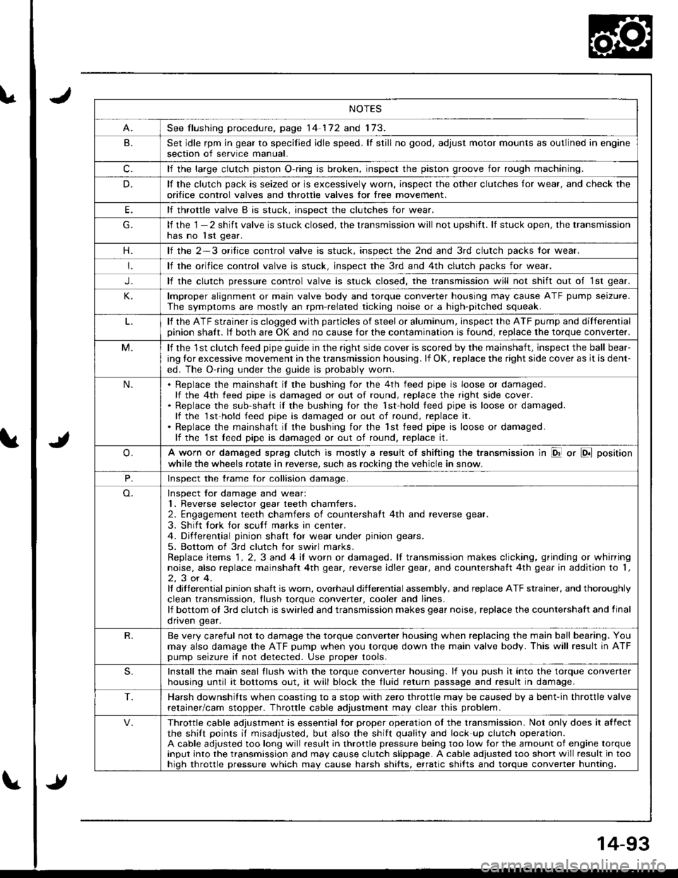
NOTES
See flushing procedure, page 14-172 and 173.
B.Set idle rpm in gear to specilied idle speed. lf still no good, adjust motor mounts as outlined in enginesection of service manual.
c.lf the large clutch piston O-.ing is broken, inspect the piston groove for rough machining.
D.lf the clutch pack is seized or is excessively worn, inspect the other clutches lor wear, and check the
orifice control valves and throttle valves for free mov€ment.
E.lf throttle valve B is stuck. insDect the clutches for wear.
lf the 1 - 2 shift valve is stuck closed, the transmission will not upshitt. lf stuck open, the transmissionhas no lst gear.
H.lf the 2-3 orilice control valve is stuck, inspect the 2nd and 3rd clutch packs for wear.
lf the orifice control valve is stuck. inspect the 3rd and 4th clutch packs for wear.
J.lf the clutch pressure control valve is stuck closed, the transmission will not shift out oI 1st gear.
lmproper alignment or main valve body and torque converter housing may cause ATF pump seizure.
The symptoms are mostly an rpm-related ticking noise or a high-pitched squeak.
lf the ATF strainer is clogged with particles of steel or aluminum, inspect the ATF pump and differentialpinion shaft. lf both are OK and no cause for the contamination is found, replace the torque converter.
M.lf the 1st clutch feed pipe guide in the right side cover is scored by the mainshaft, inspect the ball bear-
ing lor excessive movement in the transmission housing. lf OK, replace the right side cover as it is dent-
ed. The O-ring under the guide is probably worn.
N.Replace the mainshaft if the bushing for the 4th feed pipe is loose or damaged.lf the 4th feed pipe is damaged or out of round, replace the right side cover.Replace the sub-shaft il the bushing for the 1st-hold teed pipe is loose or damaged.lf the 1st-hold teed pipe is damaged or out of round, replace it.
Replace the mainshaft iI the bushing for the lst feed pipe is loose or damaged.lf the 1st leed pipe is damaged or out of round, replace it.
A worn or damaged sprag clutch is mostly a result of shifting the transmission in El or LDll position
while the wheels rotate in reverse, such as rocking the vehicle in snow.
P.Inspect the trame for collision damage.
Inspect lor damage and wear:1. Reverse selector gear teeth chamfers.2. Engagement teeth chamfers of countershaft 4th and reverse gear.
3. Shift fork for scuff marks in center.4. Differential pinion shaft tor wear under pinion gears.
5. Bottom of 3rd clutch for swirl marks.Replace items 1 . 2, 3 and 4 iI worn or damaged. lf transmission makes clicking, grinding or whirringnoise, also replace mainshaft 4th gear, reverse idler gear, and countershatt 4th gear in addition to '1,
2,3or4.It differential pinion shalt is worn, overhaul differential assembly, and replace ATF strainer, and thoroughly
clean transmission, tlush torque conveder, cooler and lines.lf bottom ot 3rd clutch is swirled and transmission makes gear noise, replace the countershaft and final
onven qear.
R.Be very careful not to damage the torque converter housing when replacing the main ball bearing. You
may also damage the ATF pump when you torque down the main valve body. This will result in ATFpump seizure if not detected. Use proper tools.
S.Install the main seal llush with the torque converter housing. lf you push it into the torque converterhousing until it bottoms out. it will block the fluid return passage and result in damage.
T.Harsh downshifts when coasting to a stop with zero throttle may be caused by a bent-in throttle valve
retainer/cam stopper. Throttle cable adjustment may clear this problem.
Throttle cable adjustment is essential tor proper operation ol the transmission. Not only does it affectthe shift points if misadjusted, but also the shift quality and lock up clutch operation.A cable adjusted too long will result in throttle pressure being too low for the amount of engine torqueinput into the transmission and may cause clutch slippage. A cable adjusted too short will result in toohiqh throttle pressure which may cause harsh shifts, erratic shifts and torque converter hunting.
Page 511 of 1681
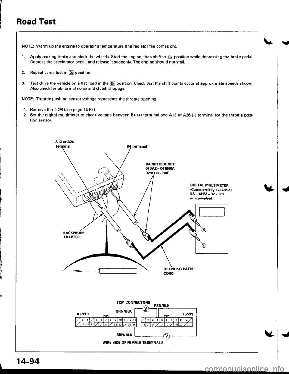
Road Test
NOTE: Warm up the engine to operating temperature (the radiator fan comes on).
1. Apply parking brake and block the wheels. Start the engine, then shift to @ position while depressing the brake pedal-
Depress the accelerator pedal, and release it suddenly. The engine should not stall.
2. Repeat same test in E position.
3. Test drive the vehicle on a flat road in the @ position. Check that the shift points occur at approximate speeds shown.
Also check for abnormal noise and clutch slippage.
NOTE: Throttle position sensor voltage represents the throttle opening.
-1. Remove the TCM (see page 14-52).-2. Set the digital multimeter to check voltage between 84 (+) terminal and A13 or A26 (-) terminal for the throttle posi-
tion sensor.
84 Terminal
DIGITAL MULTIMETER(Commercially availablelKS - AHM -32 - 003oa oquivalent
, 14-94
TCM CONNECTORS
WIRE SIDE OF FEMALE TERMINALS
i
J
Page 513 of 1681
Road Test
(cont'dl
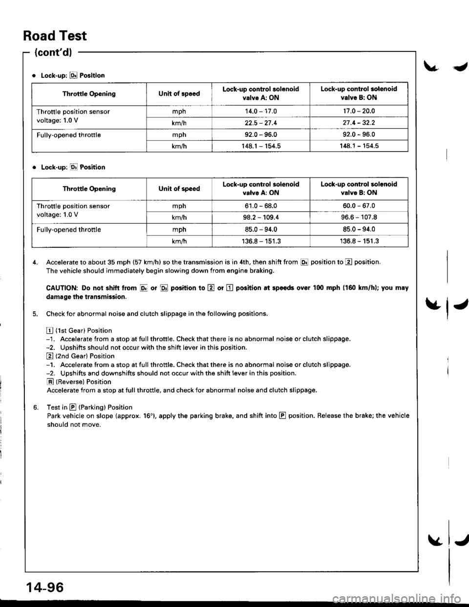
Lock-up: E Position
. Lock-up: Ell Position
4. Accelerate to about 35 mph (57 km/h) so the transmission is in 4th, then shitt from E position to E position.
The vehicle should immediately begin slowing down from engine braking.
CAUTION: Do noi shitt lrom I or $ position to E or E position 8t speeds over l0o mph (160 km/h); you may
damage the transmission.
5. Check for abnormal noise and clutch slippage in the following positions,
E {1st Gear} Position-1. Accelerate from a stop at fullthrottle. Check that there is no abnormal noise or clutch slippage.-2. Upshifts should not occur with the shift lever in this position.
E (2nd Gear) Position-1. Accelerate from a stop atfull throttle. Check that there is noabnormal noiseorclutch slippage.-2. Upshifts and downshifts should not occur with the shift lever in this position.
E (Reverse) Position
Accelerate from a stop at tull throttle, and check for abnormal noise and clutch slippage.
6. Test in E (Parking) Position
Park vehicle on slope {app.ox. 16'}, apply the parking brake, and shift into E position. Release the brake; the vehicle
should not move.
Throttle OpeningUnit of spoedLock-up control solenoid
valve A: ON
Lock-up contlol solenoid
valve B: ON
Throttle position sensor
voltage: 1.0 V
mph14.0 - 17.017 .0 - 20.0
km/h22.5 - 27 .427 .4 - 32.2
Fully-opened throftlemph92.0 - 96.092.0 - 96.0
km/h148.1 - 154.5148.1- 154.5
Throttle OpeningUnit of speedLock-up conirol 3olenoid
valve A: ON
Lock-up control solonoid
valvs B: ON
Throttle position sensor
voltage: 1.0 V
mph61.0 - 68.060.0 - 67.0
km/h98.2 - 109.496.6 - 107.8
Fully-opened throttlempn85.0 - 94.085.0 - 94.0
km/h136.8 - 151.3'136.8 - 151.3
14-96
-
Page 514 of 1681
Stall Speed
V
€nt transmission damage, do not tost stall speod for mol€ than
shitt tho lever while raising the engina speed,
10 soconds at a time.
L
CAUTION:
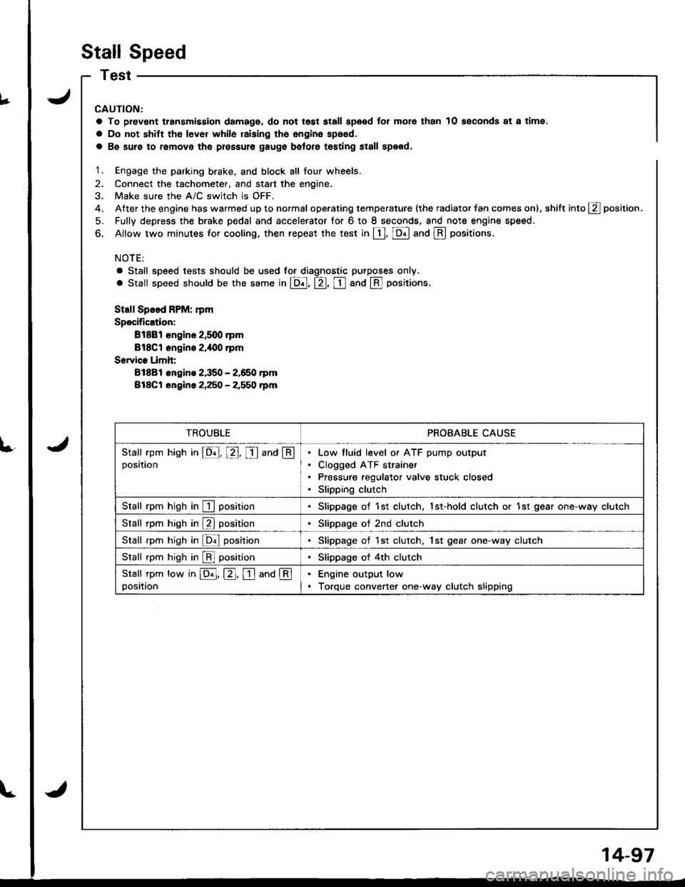
a To prev€nt transmission damage, do not tost stall speod for mol€ than 10 soconds at a time.
a Do not shitt tho lever while raising the engina speed,
a Be suro to remove tho plossule gaugo bolore testing st8ll spe€d.
1. Engage the parking brake. and block all lour wheels.
2. Connect the tachometer, and start the engine,
3. Make sure the A/C switch is OFF.
4. After the engine has warmed up to normal operating temperature {the radiator fan comes on), shift into g position.
5. Fully depress the brake pedal and accelerator for 6 to I seconds. and note engine speed.
6. Allow two minutes for cooling, then repeat the test in [, [Dll and @ oositions.
NOTE:
a Stall speed tests should be used tor diagnostic purposes only.
. Stall speed should be the same in E, tr, tr and @ Fositions.
Stall Speed FPM: rpm
Specification:
Bl88l €ngine 2,5q) rpm
Bl8Cl engine 2.i|{10 .pm
Sorvice Limit:
81881 engins 2,350 - 2,650 rpm
Bl8Ct ongine 2,250 - 2,550 rpm
TROUBLEPROBABLE CAUSE
Stall rpm hish in E, E, I and @position
Low tluid level or ATF pump output
Clogged ATF strainer
Pressure regulator valve stuck closed
Slipping clutch
Stall rpm high in I positionSlippage of 1st clutch, 1st-hold clutch or 1st gear one-way clutch
Stall rpm high in E positionSlippage of 2nd clutch
Stall rpm high in ldnl posirionSlippage of 1st clutch. 1st gear one-way clutch
Stall rpm high in [!l positionSlippage of 4th clutch
Stall rpm low in E, E. I and @position
Engine output low
Torque convener one-way clutch slipping
14-97
Page 515 of 1681
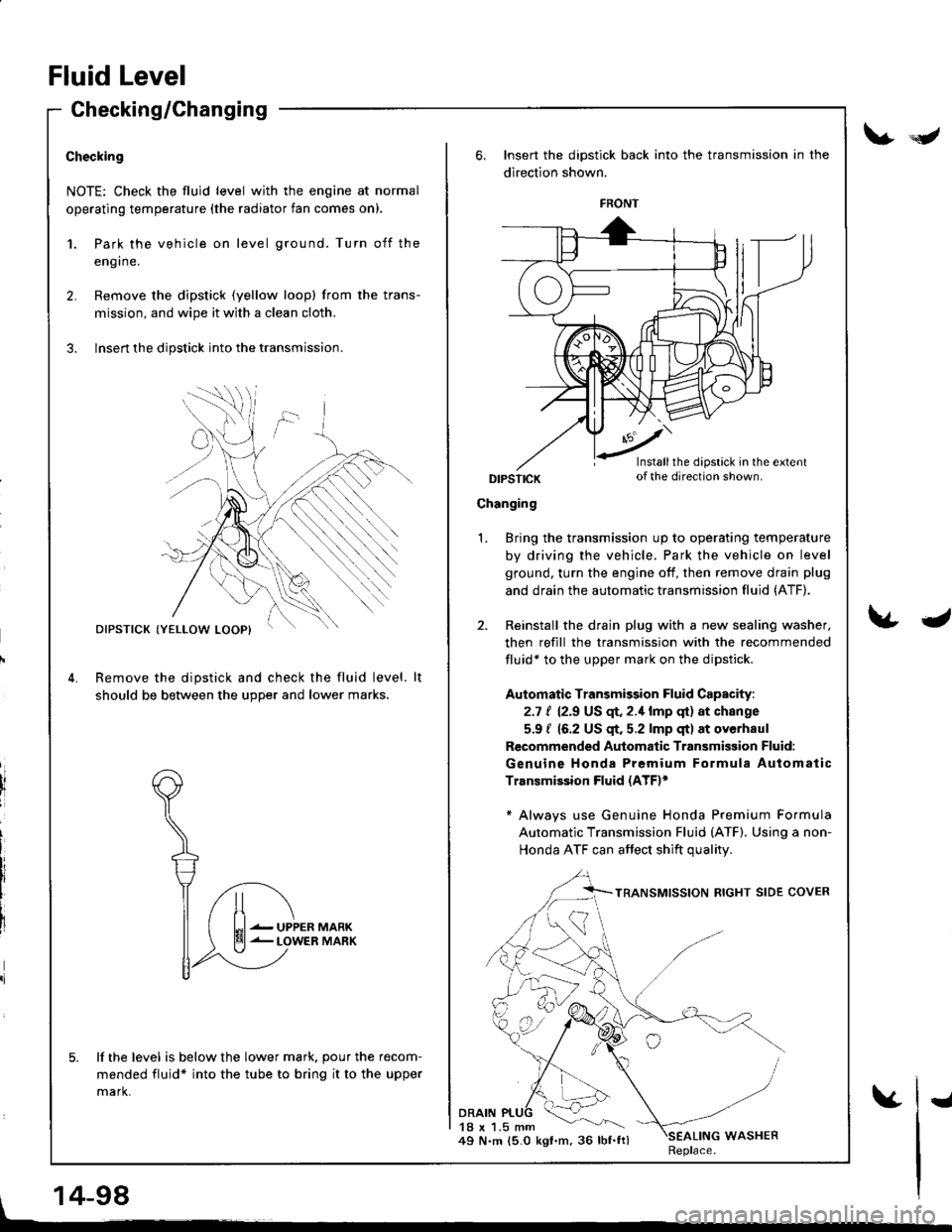
Checking/Changing
Checking
NOTE: Check the fluid level with the engine at normal
operating temperature (the radiator fan comes on).
1.
2.
Park the vehicle on level ground. Turn off the
eng I ne.
Remove the dipstick (yellow loopl from the trans-
mission, and wipe it with a clean cloth.
Insert the dipstick into the transmission.
Remove the dipstick and check the fluid level.
should be between the u9Der and lower marks.
lf the level is below the lower mark. pour the recom-
mended fluid* into the tube to bring it to the upper
mark.
DIPSTICK
UPPERLOWER
Insert the dipstick back into the transmission in the
direction shown.
DIPSTICK
Changing
DRAIN18 x 1.5 mm49 N.m 15.0 kgt.m, 36 lbf.ftl
Bring the transmission up to operating temperature
by driving the vehicle. Park the vehicle on level
ground, turn the engine off, then remove drain plug
and drain the automatic transmission fluid (ATF).
Reinstall the drain plug with a new sealing washer,
then refill the transmission with the recommended
fluid* to the upper mark on the dipstick.
Automatic Transmission Fluid Capacity:
2.7 t 12.9 US qr,2.1lmp qt) at change
5.9 / 16.2 US $. 5.2 lmp qt) at overhaul
Recommended Automatic Transmisgion Fluid:
Genuine Honda Premium Formula Automatic
Transmission Fluid (ATE*
* Always use Genuine Honda Premium Formula
Automatic Transmission Fluid (ATF). Using a non-
Honda ATF can affect shift qualitv
1.
WASHERReplace.
FRONT
Installthe dipstick in the extentof the direction shown.
Fluid Level
V*Y
\&J
, 14-98
vI
Page 516 of 1681
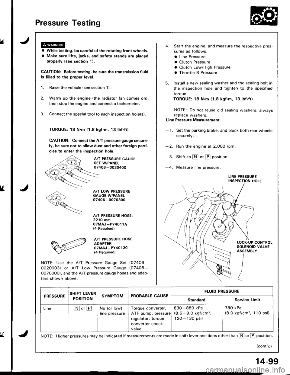
Pressure Testing
a While testing, be careJulot the rotating front wheels.
a Make sule litts, iacks, and safety stands are placed
properly (see section 1).
CAUTION: Befoie testing, be sure the transmission fluid
is filled to the proper level.
'1. Raise the vehicle {see section 'll.
2. Warm up the engine (the radiator fan comes on),
then stop the engine and connect a tachometer.
3. Connect the special tool to each inspection hole(s).
TOROUE: 18 N.m l1-8 kgt.m, 13lbf.ftl
CAUTION: Connect the A/T pressure gauge secure-
ly, be sure not to allow dust and olher foreign pani-
cles to enter the inspection hole.
A/T PRESSURE GAUGESET W/PANEL07406 -0020400
A/T LOW PRESSUREGAUGE W/PANEI.07406-OO70300
A/T PRESSURE HOSE,2210 mmOTMAJ _PY4O1 1A{4 Required}
A/T PRESSURE HOSEADAPTER07MAJ -PY40120
l4 Requiredl
NOTE: Use the A/T Pressure Gauge Set (07406-
OO2O0O3) or A/T Low Pressure Gauge (07406-
OOTOOOO), and the A/T pressure gauge hoses and adap-
ters shown above.
4. Start the engine, and measure the respective pres
sures as follows.
a Line Pressure
a Clutch Pressure
a Clutch Low/High Pressure
a Throttle B Pressure
5. Install a new sealing washer and the sealing bolt in
the inspection hole and tighten to the specified
torque.
TOROUE:18 N.m (1.8 kgf.m, 13lbf.ft)
NOTE: Do not reuse old sealing washers; alwaysreplace washers.
Line Pressure Measurement
-1. Set the parking brake, and block both rear wheels
securely.
-2. Run the engine at 2,000 rpm
3. Shift to S or @ position.
4. lMeasure line pressure.
LINE PRESSUREINSPECTION HOLE
LOCK-UP CONTROLSOLENOID VALVEASSEMBLY
PRESSURESHIFT LEVER
POST ONSYMPTOMPROBABLE CAUSEFLUID PRESSURE
StandardService Limit
LineNo,BNo (or low)
Irne pressure
Torque converter,
ATF pump, pressure
regulator, torque
converter check
830 88o kPa
(8.5 9.O kgf/cm'�,
1 20 130 psi)
78O kPa(8.O kgf/cm'�, 1 10 psi)
NOTE: Higher pressures may be indicated if measurements are made in shitt lever positions other than S or f, position.
{cont'd )
14-99
Page 517 of 1681
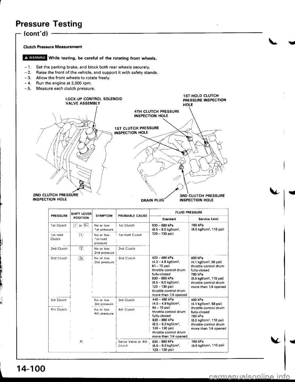
Pressure Testing
.Y
Clutch P.6ssure Measuremgnt
@ wnirc testing. be caretul ot the rorating tront wheels.
- 1. Set the parking brake, and block both rear wheels securely.- 2. Raise the front of the vehicle, and support it with safety stands.- 3. Allow the front wheels to rotate freelv.- 4. Run the engine at 2.000 rpm.- 5. Measure each clutch oressure.
LOCK"UP CONTROL SOLENOIDVALVE ASSEMBLY
lST-HOLD CLUTCHPRESSURE IiISPECTIONHOLE
4TH CLUTCH PRESSUREINSPECTION HOLE
1ST CLUTCH PRESSURE
INSPECTION HOLE
t
DRAIN P
l,i
PfiESSURESTIIFT LEV€RPOStTtONSYMPTOMPROAAALE CAUSEFLUID PRESSURE
S€rvico Limit
lst Clutch11 o' D;llst Clurch830 - 880 kPa(8.5 - 9.0 kgflcm,120 - 130 psi)
780 kPa(8.0 kgflcm,, 1 10 psi)
Clutch
zno cruiltr
1No or low lsr hold C utch
lr,2nd C ltch
2nd Clutch420 - 440 kPa14.3 - 4.9 kg?cm,,61 - 70 psi)throttle controldrumtully-closed8:|0 - 880 kPa18.5 - 9.0 kgflcm'�,120 - 130 psi)throttle controldrummore than 1/4 ooened
400 kPa(4.1 kg?cm,,58 psi)throttle control drum
780 kPa(8.0 kgflcm,, 110 psi)throttle controldrummore than 1/4 opened
3rd Clulch No or ow
I , !,q !le"**4th Clutch No or Low4th pressufe
3rd Clurch
a,r il","r,
Clulch
440 - 480 kPa(4.5 - 4.9 kgtcm,,64 - 70 psi)throttle control drumfully-closed830 - 880 kPa{8.5 - 9.0 ksf/cm'�,120 - 130 psi)throttle control drumrn9l9!q l/4 olqg
830 - 880 kPa(8.5 - 9.0 kgtcm?,120 - 130 psi)
400 kPa14.1 kgvcm,,58 psi)throttle control drumfully-closed780 kPa(8.0 kgflcm'�, 110 psi)throttle control drummore th6n 1/4 opened
zeo rpi(8.0 kgtcm'�, 110 Psa,
14-100
I
Page 518 of 1681
\a
t
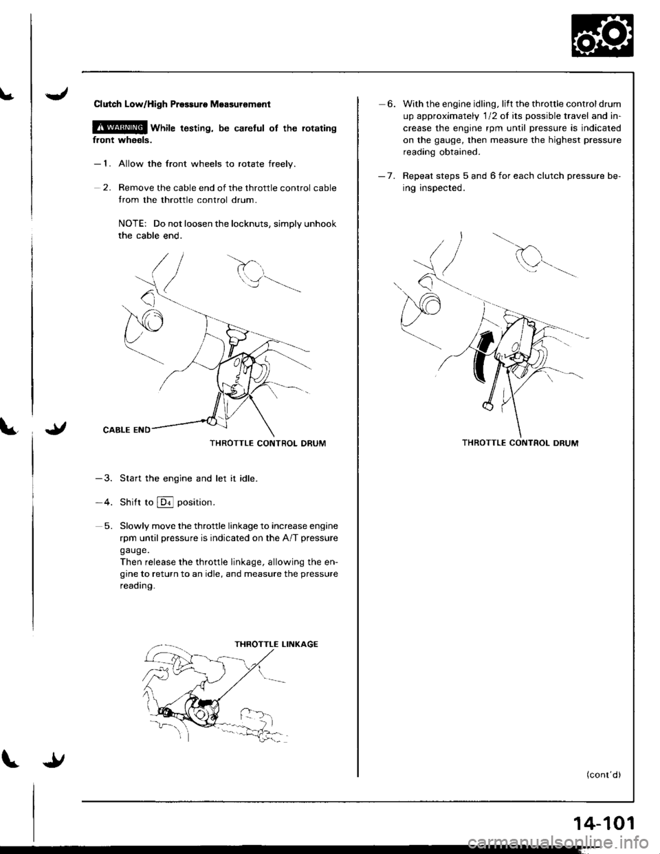
Clutch LoWHigh Prossuro Moasursment
@ wnire t6sting, be carelul of the rotating
front whaols.
- 1. Allow the front wheels to rotate freelv.
2. Remove the cable end of the throttle control cable
trom the throttle control drum.
NOTE: Do not loosen the locknuts, simply unhook
the cable end.
THROTTLE CONTROL DRUM
-3. Start the engine and let it idle.
-4. Shitt to @ position.
5. Slowly move the throttle linkage to increase engine
rpm until pressure is indicated on the A/T pressure
gauge.
Then release the throttle linkage, allowing the en-
gine to return to an idle, and measure the pressure
reading.
6. With the engine idling. lift the throttle controldrum
up approximately 'l12 of its possible travel and in-
crease the engine rpm until pressure is indicated
on the gauge, then measure the highest pressure
reading obtained.
- 7. Repeat steps 5 and 6 for each clutch pressure be-
ing inspected.
d
Q^--,'.-
THROTTLE CONTROL DRUM
(conr'd)
14-101
Page 520 of 1681
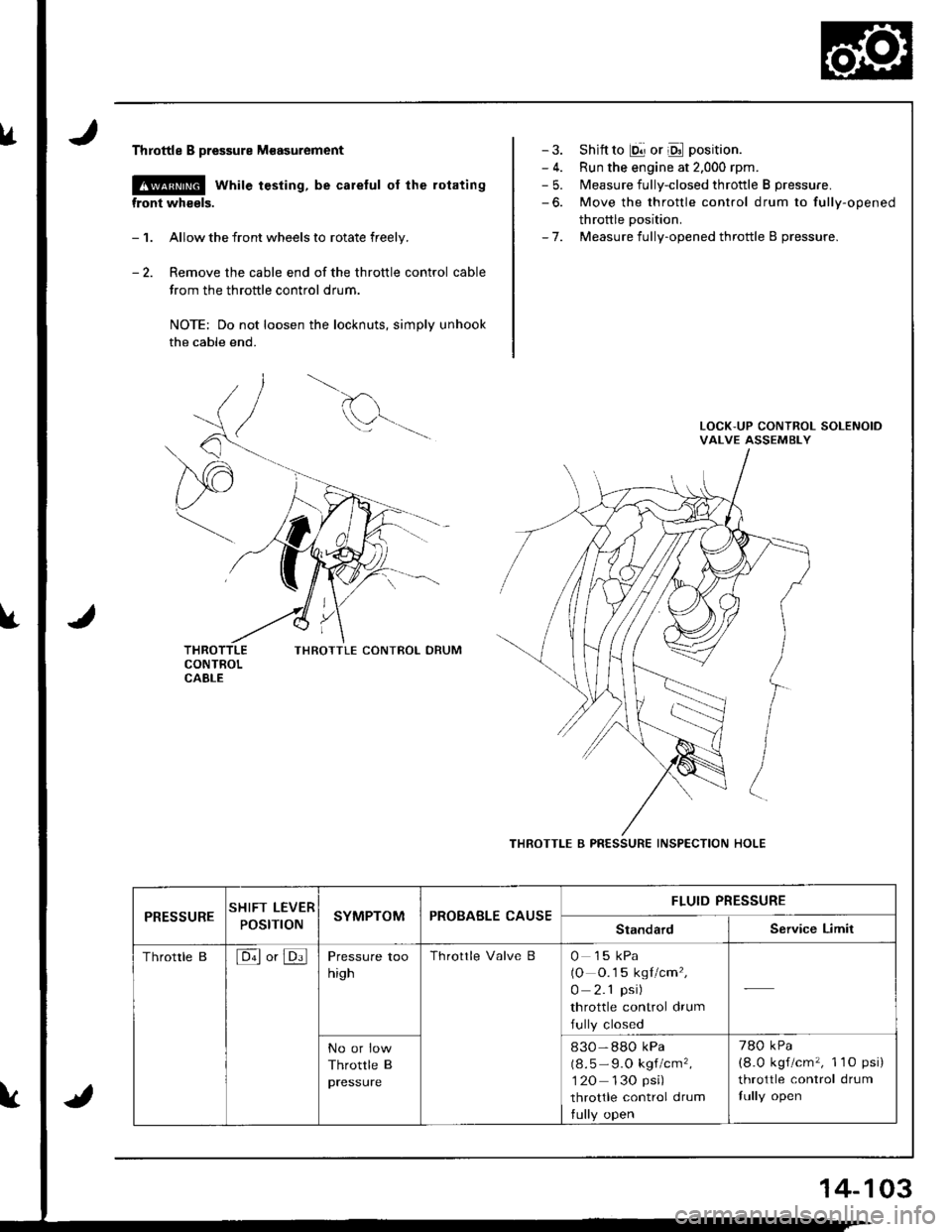
lrThrottle B pressure M€asurement
@ while testing, be careful of the rotating
front wheels.
- 1. Allow the front wheels to rotate freely.
- 2. Remove the cable end of the throttle control cable
trom the throttle control drum.
NOTE: Do not loosen the locknuts, simply unhook
the cable end.
THROTTLE CONIBOL DRUM
- 3. Shift to E!] or Oll position.
- 4. Run the engine at 2.000 rpm.- 5. Measure fully-closed throttle B pressure.
-6. Move the throttle control drum to fully-opened
throttle Dosition.- 7. Measure fully-opened throttle B pressure.
THROTTLE B PRESSURE INSPECTION HOLE
PRESSURESHIFT LEVER
POStnONSYMPTOMPROBABLE CAUSEFLUID PRESSURE
StandardService Limit
Throttle B[6ll or JDi]Pressure too
high
Throttle Valve B0 15 kPa(O O.1 5 kgl/cm',
0 2.1 psi)
throttle control drum
fully closed
No or low
Throttle B
pressure
830-88O kPa
(8.5 - 9.O kgf/cm',
1 20 130 psi)
throttle control drum
tully open
780 kPa
(8.0 kgf/cm'�, 1 1O psi)
throttle control drum
fully open
14-103
Page 521 of 1681
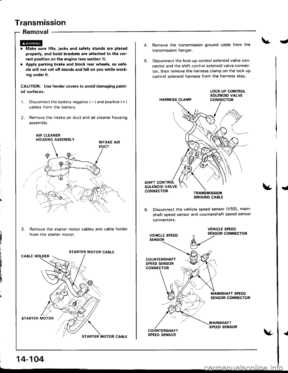
Transmission
Removal
. Make sure lifts, iacks and salety stands are placed
properly, and hoist brackets are attached to lhe cor-
rect position on the engine (see section 11.
. Apply parking brake and block real wheels, so vehi-
cle will nol roll off stands and fall on you while work-
ing under it.
CAUTION: Use fender covers to avoid damaging paint-
ed surtaces.
1 . Disconnect the battery negative (- ) and positive { + )
cables from the battery.
2. Remove the intake air duct and air cleaner housing
assemoty.
AIR CLEANERHOUSING ASSEMBLY
Remove the starter motor cables and cable holder
from the starter motor.
MOTOR CABLECABLE HOLDER
STARTER MOTOR'/,/ \
STARTER MOTOR CABI-E
14-104
-
5.
Remove the transmission ground cable from the
transmission hanger.
Disconnect the lock-up control solenoid valve con-
nector and the shift control solenoid valve connec-
tor, then remove the harness clamp on the lock-up
control solenoid harness from the harness s1ay.
HARNESS CLAMP
TRANSMISSIOIGROUND CABLE
Disconnect the vehicle speed sensor (VSS), main-
shalt speed sensor and countershalt speed sensor
connecrors.
{
6.
VEHICLE SPEED
VEHICLE SPEED
ll t2tor coNNEcroR
V
MAINSHAFT SPEEDSENSOR CONNECTOR
MAINSHAFTSPEED SENSORCOUNTERSHAFTSPEED SENSOR{