G401 HONDA INTEGRA 1998 4.G Workshop Manual
[x] Cancel search | Manufacturer: HONDA, Model Year: 1998, Model line: INTEGRA, Model: HONDA INTEGRA 1998 4.GPages: 1681, PDF Size: 54.22 MB
Page 1002 of 1681
II
JFrom page 21- 14
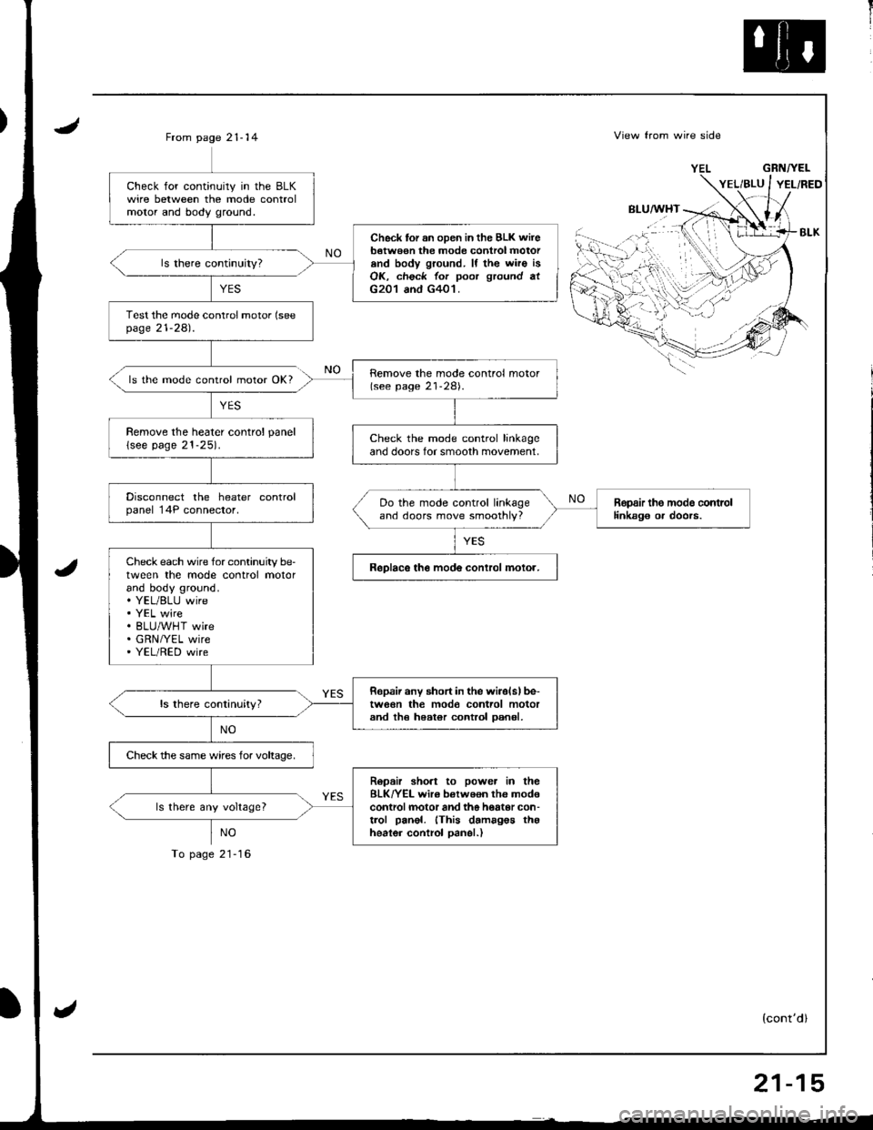
ls the mode control motor OK?
YES
NO
To page 21-16
View from wire side
BLU/WHT
GRNTYEL
(cont'dl
Check for continuily in the BLKwire between the mode controlmolor and body ground.
Check tor an oDen in the BLK wireb€twe€n the mode control motorand body ground. lf the wiro isOK, check for poor ground atG201 and G401.
Test the mode conlrol motor (seepage 21-281.
Remove the mode control motor(see page 21-28).
Remove the heater control panel
lsee page 21-25).Check the mode control linkageand doors for smooth movement,
Disconnect the heater controlpanel 14P connector.Ropair the modo contrcllinkag€ or doors.Do the mode control linkageand doors move smoothly?
Check each wire for continuity be-tween the mode control motorand body ground.. YEL/BLU wire. YEL wire. BLU/WHT wire. GRN/YEL wire' YEL/RED wire
ReDlace the mode conlrol molor.
Ropaii any short in the wiiolslbe-tw6€n the mod€ control motorand th€ heater control oan6l,
Check the same wires for voltaoe,
Ropair sho.t to power in theBLK/YEL wir€ betweon the mod€controlmotor and the hottor con-trol panel. (This damagos thgheater control oanel.)
ls there any voltage?
,.i:...
''{
'rt'',-
21-15
Page 1023 of 1681
![HONDA INTEGRA 1998 4.G Workshop Manual Circuit Diagram
CONDENSERFANRELAY
!
BTKFED FEO
II
VIecu1xzrccl IT(l
tql
i.tli*, Tf7 r-
IBIU/RED
I-1
8LU/REO
.*.. *(if ) PRESSUFE
Y SWTCH
YEL/N4]T
lvcDIODE
- BLUiRED
I ,,,,^,-.,
IY
r.--"-G8N
I,**,
Y HONDA INTEGRA 1998 4.G Workshop Manual Circuit Diagram
CONDENSERFANRELAY
!
BTKFED FEO
II
VIecu1xzrccl IT(l
tql
i.tli*, Tf7 r-
IBIU/RED
I-1
8LU/REO
.*.. *(if ) PRESSUFE
Y SWTCH
YEL/N4]T
lvcDIODE
- BLUiRED
I ,,,,^,-.,
IY
r.--"-G8N
I,**,
Y](/img/13/6069/w960_6069-1022.png)
Circuit Diagram
CONDENSERFANRELAY
!
BTKFED FEO
II
VIecu1xzrccl IT(l
tql
i.tli*, Tf7 r-
IBIU/RED
I-1
8LU/REO
.*.. *(if ) PRESSUFE
Y SWTCH
YEL/N4]T
lvcDIODE
- BLUiRED
I ,,,,^,-.,
IY
r.-'-"'-G8N
I,**',
Y ES:1i+31'
I
ts$'fts.,1
I
I
IBLK
I
G101
BLI(BED
I
I
I
,^r^r", IFANMoToRY
I
I
I
I8LK
T
G201G401
V
IBLU€LK
f7
IBLU/Y€L
V
IBLUMHT
V
IBLU
BLU/RED BLK,YEI
"fti.. i,, )
BLK
I
G151
Page 1025 of 1681
J
Troubleshooting
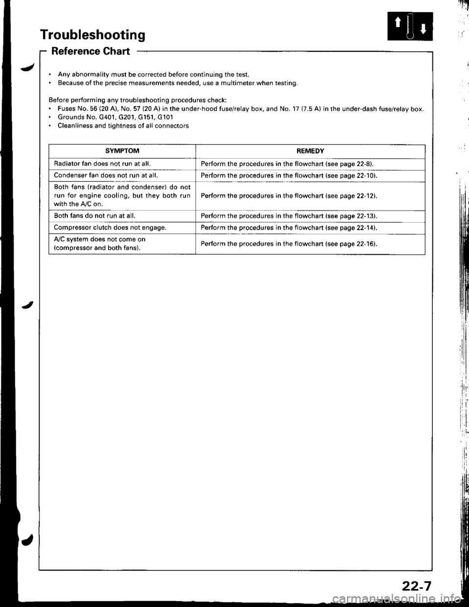
Reference Chart
. Any abnormality must be corrected before continuing the test.. Because of the precise measurements needed, use a multimeter when testing.
Before performing any troubleshooting procedures check:. Fuses No, 56 (20 A), No. 57 (20 A) in the under-hood fuse/relay box, and No. 17 {7.5 A) in rhe under-dash fuse/relay box.. Grounds No. G401, G201, G151, G101. Cleanliness and tightness of all connectors
I'IT
I
I
SYMPTOMREMEDY
Radiator fan does not run at all.Perform the procedures in the flowchart {see page 22-8).
Condenser fan does not run at all,Perform the procedures in the flowchart (see page 22-1O1.
Both fans {radiator and condenser) do not
run for engine cooling, but they both run
with the IVC on.
Perform the procedures in the tlowchart (see page 22-12).
Both fans do not run at all.Perform the procedures in the flowchart (see page 22-13).
Compressor clutch does not engage.Perform the procedures in the flowchart (see page 22-14).
l'lc system does not come on
{compressor and both fans).Perform the procedures in the flowchart (see page 22-15).
22-7
Page 1026 of 1681
Troubleshooting
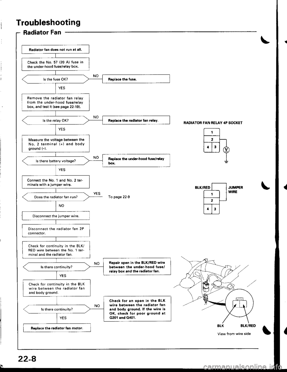
Radiator Fan
RADIATOR FAN RELAY 4P SOCKET
El2F-lt--T-- |
ujj I
I
",-*rrro [--l .u^rrrr
E lw'RE
l2-
trI
\
\
8LK BLK/RED
View from wire side\
Radiator lan does not run at all.
Chock the No. 57 (20 A) fuse in
the undeFhood fuse/relay box.
Remove the radiator tan relayfrom the under-hood fuse/rolaybox, and test it (see page 22-19).
Measuro the voltag€ betwogn theNo.2 terminal (+) and bodyground (-).
ls there battery voltage?
Connect the No. 1 and No. 2 ter-minals with a jumper wire.
Does the radiator fan run?
Check for continuity in the BLK/RED wire between the No. 1 ter-minal and the radiator fan.
Repair open in tho BLK/RED wir6b6twaon the undor-hood fuso/r6l6v box and the radirtorf6n.ls there continuity?
Check Ior continuity in the BLKwire between the radiator lanand body ground.
Chock for.n opon in tho BLKwiro botween tho .adiator fanand body ground, It tho wire i3OK, check for poor ground rtG201 and G401.
ls there continuity?
Roolace the radiator tan motor.
10 page 22-9
22-8
Page 1036 of 1681
Troubleshootang
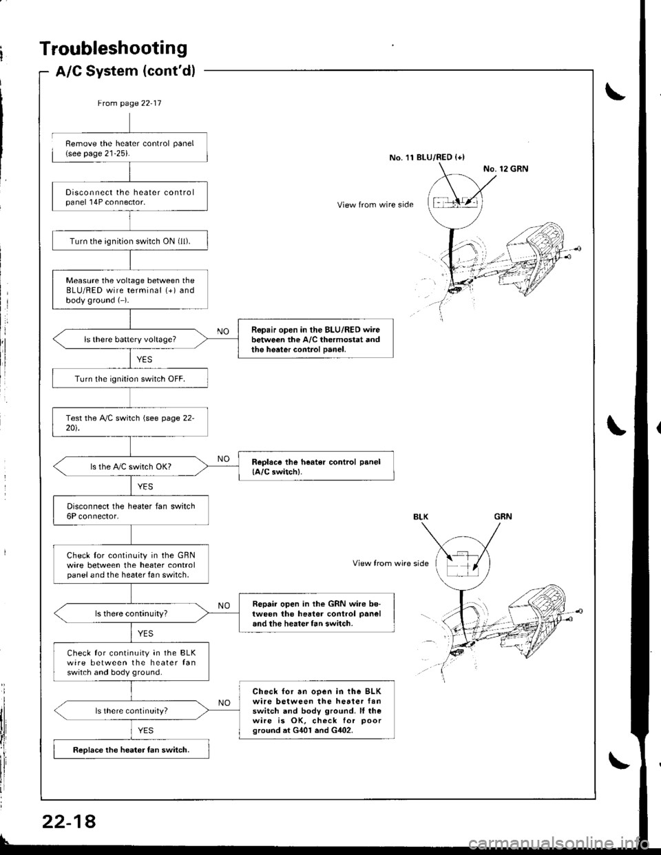
A/C System (cont'd)
8
Ftom page 22-17
Disconnect the heater controlpanel 'l4P connector.
Turn the ignition switch ON (ll).
Measure the voltage between theBLU/RED wire terminal (+) andbody ground (-).
Ropair open in the BLU/RED wirebetween the A/C thermostat andthe heater control Danel,
Turn lhe ignition switch OFF.
ls the PVC switch OKI
Disconnect the heater fan switch6P connector.
Check lor continuity in the GBNwire between the heater controlpanel and the he6ter fan switch,
Repair open in the GRN wire be-tween the hester control panel
and the heater fan switch.
Check for continuity in the BLKwire between the heater fanswitch and body ground.
Check for an ooen in the BLKwire between the hetter fanswitch and body ground. ll rhewire is OK, check for poorground at G401 and G402.
ls there continuity?
Reolace the heater fan switch.
Remove the heater control panel(see page 21-25).No.'11 BLU/RED {+)
View from wire side
View from wire side
22-1
Page 1070 of 1681
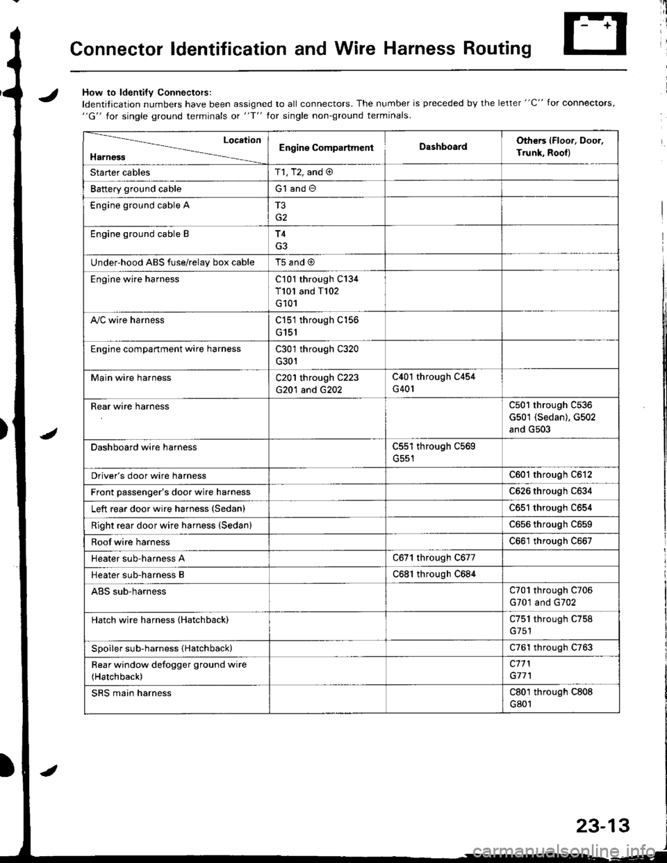
Connector ldentification and Wire Harness Routing
JHow to ldenti{v Connectors:
ldentification numbers have been assigned to all connectors. The number is preceded by the letter "C" for connectors,"G" for single ground terminals ot "f" lor single non-ground terminals.
/
Location
HarnossEngine CompartmentDashboardOthers (Floor, Door,
Trunk. Rooll
Starter cablesT1, T2, and @
Battery ground cableG1 and O
Engine ground cable A
G2
Engine ground cable BT4
G3
Under-hood ABS fuse/relav box cableT5 and @
Engine wire harnessC101 through C134
T101 and T102
G101
A,/C wire harnessC151 through C156
G151
Engine compartment wire harnessC301 through C320
G301
Main wire harnessC201 through C223
G20'l and G202
C40l through C454
G401
Rear wire harnessC501 through C536
G501 (Sedan), G502
and G503
Dashboard wire harnessC551 through C569
G551
Driver's door wire harnessC601 through C612
Front passenger's door wire harnessC626 through C634
Left rear door wire harness (Sedan)C65l through C654
Right rear door wire harness (SedanlC656 throughc659
Roof wire harnessC661 through C667
Heater sub-harness AC671 through C677
Heater sub-harness BC68l through C684
ABS sub-harnessC701 through C706
G701 and G702
Hatch wire harness (Hatchback)C751 through C758
Spoiler sub-harness {Hatchback)C761 through C763
Rear window defogger ground wire
(Hatchback)
c11 l
G77'l
SRS main harnessC801 through C808
G801
23-13
Page 1083 of 1681
Connector ldentification and Wire Harness Routing
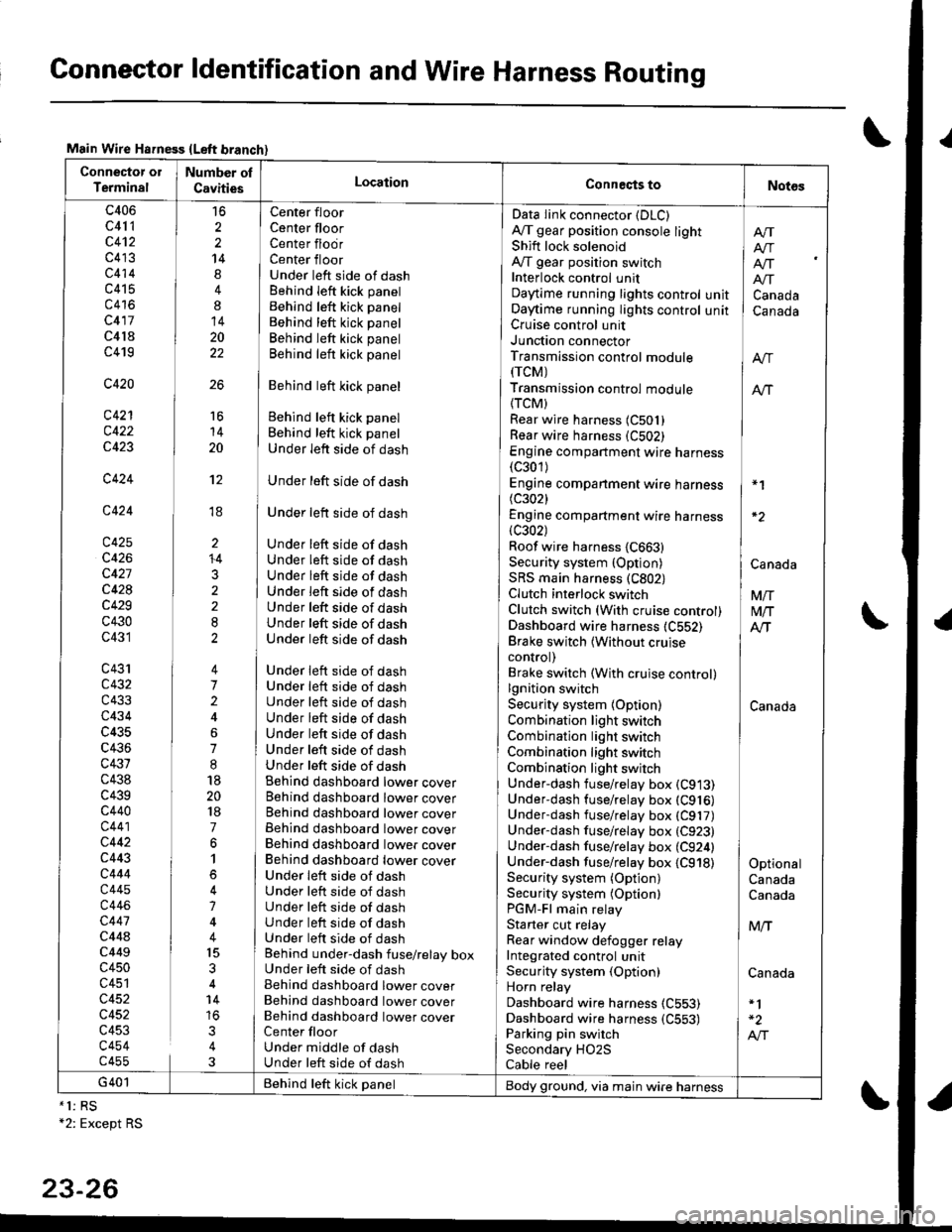
Main Wire Hsfness {Left branch}
Connector ol
TerminalNumber ol
CavitiesLocationConneqts toNot6s
c406
c41 1
c4't2
c413
c414
c415
c416
c417
c4l8
c419
c420
c421
c422
c423
c424
c424
c425
c426
c427
c428
c429
c430
c431
c43'rc432
c433
c434
c435
c436
c431
c438
c439c440
c441
c442
c443
c444
c445
c446
c447
c44ac449
c450
c451
c452
c452
c453
c454c455
16
2
2
14
4
8
14
20
22
26
Center floor
Center floorCenter flodrCenter floorUnder left side of dashBehind Ieft kick panel
Behind left kick panel
Behind left kick panel
Behind left kick panel
Behind left kick panel
Behind left kick panel
Behind left kick panel
Behind left kick panel
Under left side of dash
Under left side of dash
Under left side of dash
Under left side of dashUnder left side of dashUnder left side of dashUnder left side of dashUnder left side of dashUnder left side of dashUnder left side of dash
Under left side of dashUnder left side of dashUnder left side of dashUnder left side of dashUnder left side of dashUnder left side of dashUnder left side of dashBehind dashboard lower coverBehind dashboard lower coverBehind dashboard lower coverBehind dashboard lower coverBehind dashboard lower coverBehind dashboard lower coverUnder leit side of dashUnder left side of dashUnder left side of dashUnder left side of dashUnder left side of dashBehind under-dash fuse/relay boxUnder left side of dashBehind dashboard lower coverBehind dashboard lower coverBehind dashboard lower coverCenter floorUnder middle of dashUnder left side of dash
Data Iink connector (DLC)
A,/T gear position console lightShift lock solenoidAy'T gear position switchInterlock control unitDaytime running lights controlOaytime running lights controlCruise control unitJunction connectorTransmission control module(rcM)
Transmission control module
{TCM)Rear wire harness (C501)
Rear wire harness (C502)
Engine compartment wire harness(c301)
Engine companment wire harness I *1
(c3021 IEngine compartment wire harness(c302) lRoof wire harness {C663} |Security system {Option) | CanaAaSRS main harness (C802) |Clutch interlock switch I VnClutch switch (With cruise control) M/TDashboard wire harness (C552) AlTBrake switch lwithout cruise Icontrol) |Brake switch (With cruise control)lgnition switch ISecurity system {Option) CanadaCombination light switch /Combination light switch ICombination light switchCombination light switchUnder-dash fuse/relay box (C913)
Under-dash fuse/relay box (C916)
Underdash fuse/relay box (C917)
Under-dash fuse/relay box (C923)
Under-dash fuse/relay box (C924) |Under-dash fuse/relay box {C918) I OptionalSecurity system (Option) CanadaSecurity system (Optionl CanadaPGM-Fl main relayStarter cut relay ] M,.fRear window defogger relay IIntegrated control unitSecurity system (Option) CanadaHorn relay
Dashboard wire harness (C553)
Dashboard wire harness {C553) | -2
Parking pin switch I A,"ISecondary HO2S
Cable reel
Afi
I Atr
lf[
unit ] Canadaunit I Canada
16
14
20
't2
ti
I'
li
ll
li
+4
3
G401 Behind teft kick panelBody ground, via main wire harness*1: RS+2: Except RS
23-26
Page 1111 of 1681
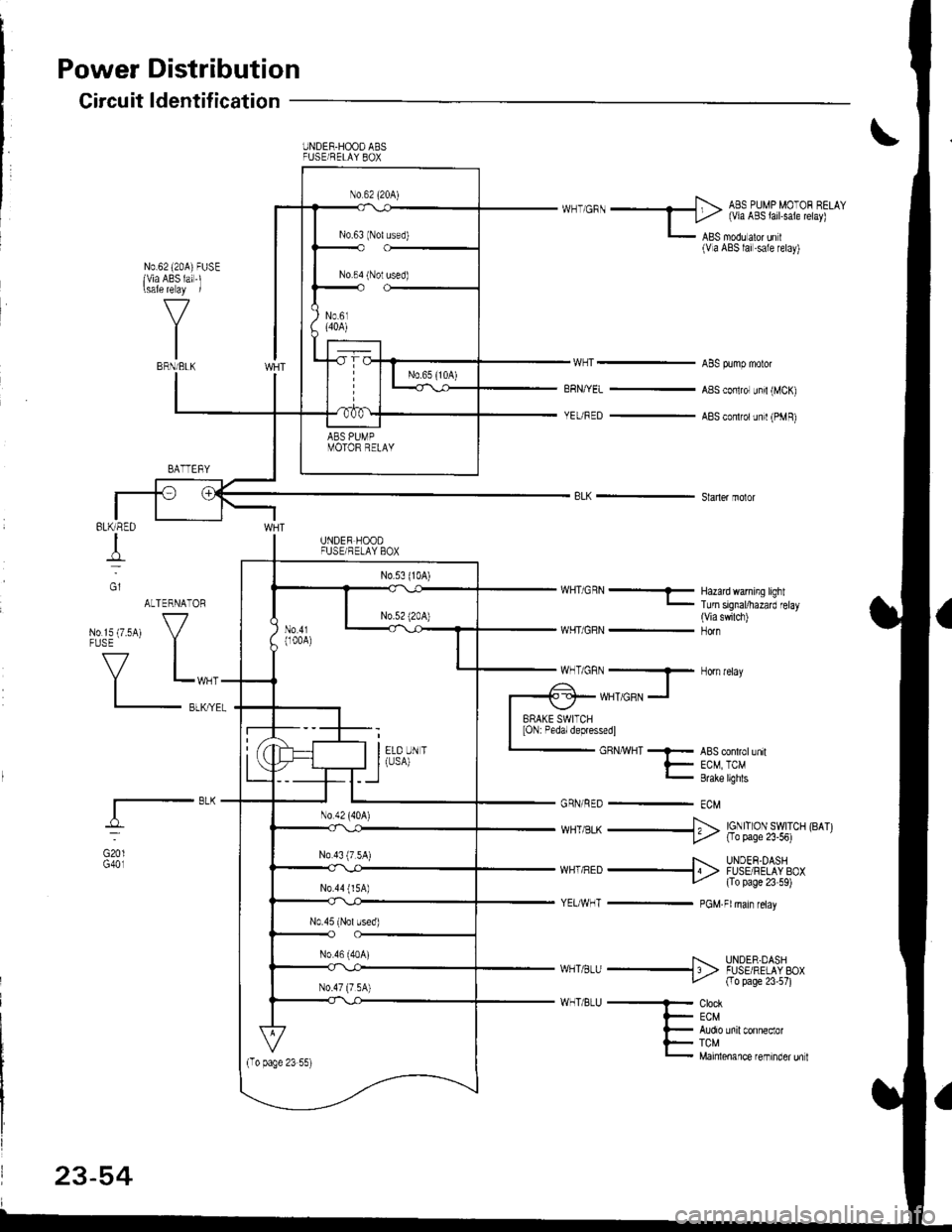
Power
Circuit
Distribution
ldentification
UNDER.HOOO ABSFUSE/RELAY 8OX
ABS OUMP MO'OF CELAY
I Li,z (via ABS lail.sale telay)
L lgS moou aror un r(Va ABS lai.sale retay)
N0.62 (20A)FUSElvia ABS lai-l\sale re ay /
ABS pump motor
ABS conlrol unir (MCK)
ABS con$olunit (PMR)
Hazad warning lightTurn signal/hazard elay(Viaswilch)Horn
BRN/YEL
YEUFED
8LK - Shner molor
BLK/RED
T
G1
GmlG401
ALTERNATORwHriGRN---
WHT/GRN -No rs {7.5A1 V"LL,,r,
_f,-"*
GRNMHT -F ABS conlrollnrt
t- EcM TcM_ &eke ughts
GRN/RED - ECM
*HT,BLK --+ ig|ryJ,itil.* F^r
F UNDEF OASHvlHi.nED -I4 > FUSE FELAY BOXLz {To page 23 59)
YEITWHT - PGM.Flmain retav
T. UNDER.DASHI/HT a_U -l 'l > .uSE RELAV 8OXfro page 23 57)
ClockECM
TCMMainlenance reminder unl
MT/GRN --T Horn relav
-ol- WHTTGRN -l
BRAKE SWITCHION: Pedal depressedl
23-54
Page 1114 of 1681
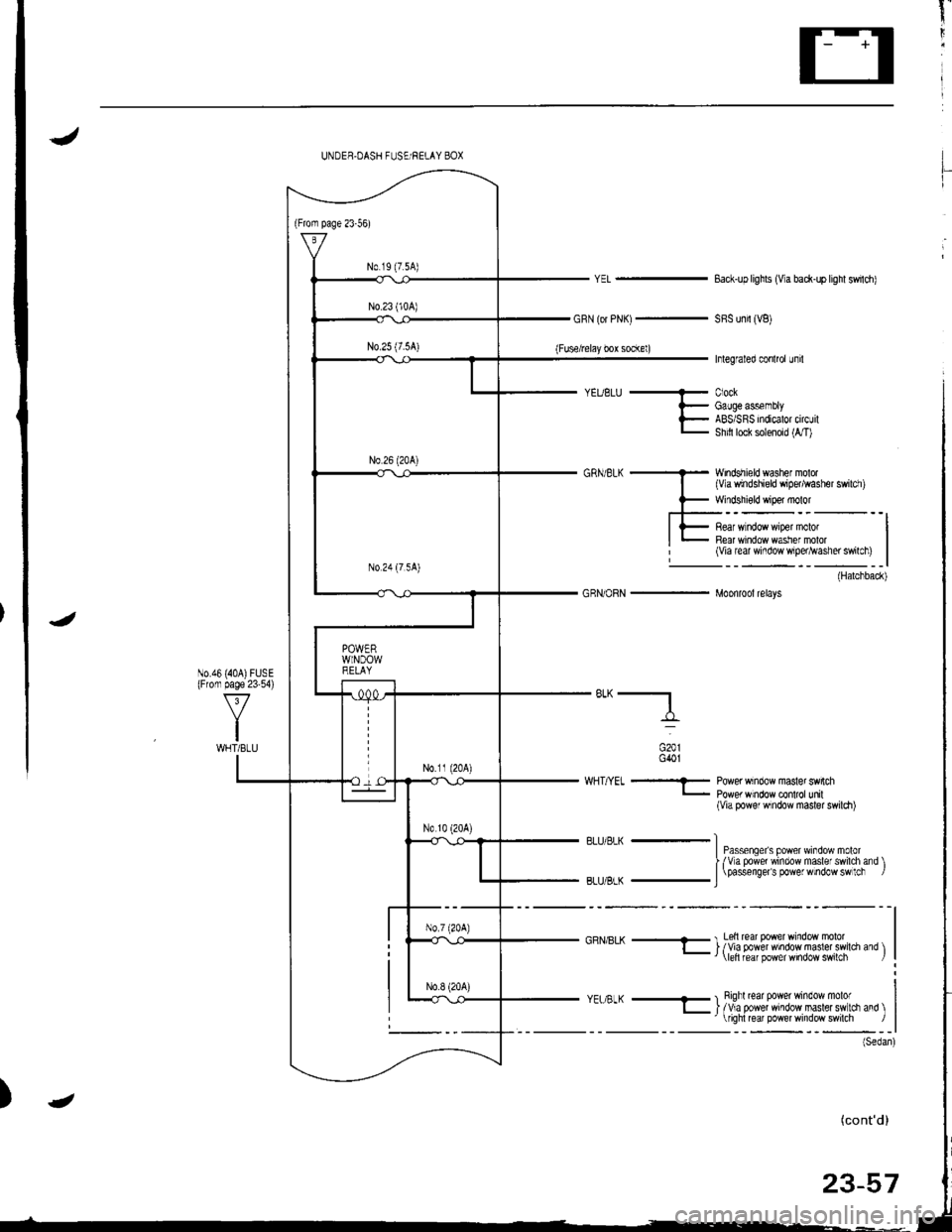
t"
li
)
UNDER.DASH FUSE RELAY BOX
N0.19 (7.5A)
J
GRN (or PNK)-
(Fusefelay bor socl(el)
Eack-up lighls (Va back-up lighl swildl)
SFS unil (VB)
Inlegraled conlrol uf il
CiockGaugeassemblyABS/S RS indicalor circuilShitl lock solenoid (1,/T)
Windshield washef molor(Vla windshield wipertrasher swildl)
Windshisld wiper molor
(Harchback)
J
GRNioRN - Moonrool relays
"*-f,_
^:".
G401
WHT/YEI - Power wrndow masler swnch- powe, w ndow contol unil(Via power wndow master swildr)
R||r/Rk -lI Passenqeis power wroow moro'I fva powe' window nasle swird ard )| \oassenoers oo
e'
noow sw lc|BLU/ gLK _ J
GRN/BLK + I Lsll lear power window molotl_ | /Via power ndowmasler switdr drd \
yEt g-K - I Rigftrear power window molo'l_ | /Va power mrdow maslerswrci and \'
iohl re Dower window swilch /
N0.46 (40A)FUsE(Fronr page 23'54)
I(cont'd)
23-57
---
Page 1115 of 1681
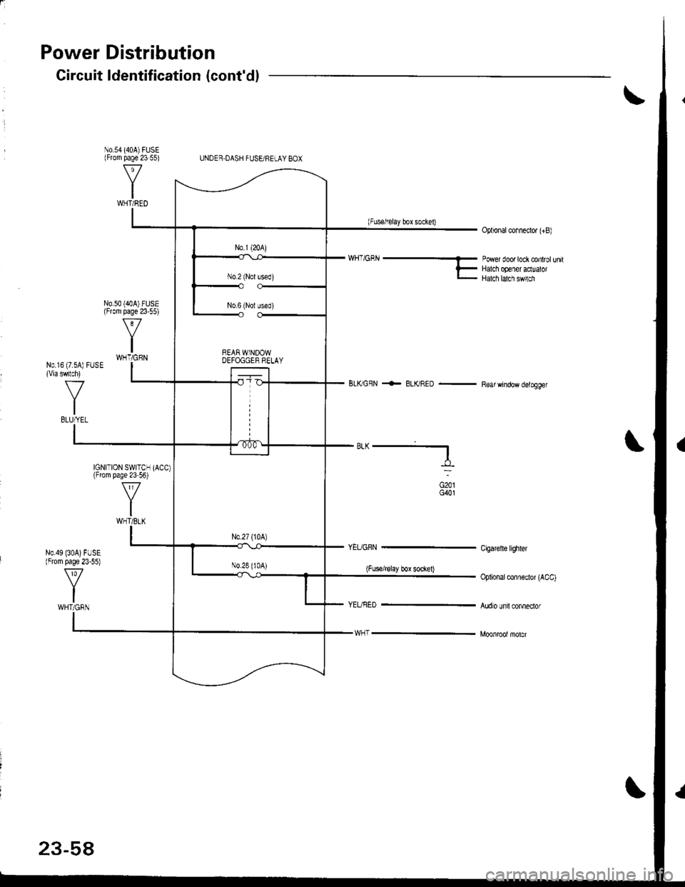
Power Distribution
N0.54 (404)FUSE(From page 23 55)
N0.49 (30A)FUSE(From page 23-55)
Gircuit ldentification (cont'dl
UNDER.DASH FUSEi FELAY BOX
(Fuserelay box sockel)Oplional conneclor (+B)
N0.50 (40A) FUSE(From page 23-55)
'/'/H_'GRN ----- rower door tock controt un,tF Halct op€ler acluatorl- Halch lalcn sw,rm
BLKGFN <- BLKRED - Rear window delogger
N0.16 (7.sA) FUSE(Viaswlch)
f7
IBLUfrEL
IGNITION SWITCHlFrom page 23 56)
ft
IWHT/BLK
"^--f,_
(Fus€irglay box soclel)
G201G401
Cigaretle lighler
Oplional conneclor (ACC)
Audro unil conneclorWHT/GRN
23-58