lock HONDA INTEGRA 1998 4.G User Guide
[x] Cancel search | Manufacturer: HONDA, Model Year: 1998, Model line: INTEGRA, Model: HONDA INTEGRA 1998 4.GPages: 1681, PDF Size: 54.22 MB
Page 149 of 1681
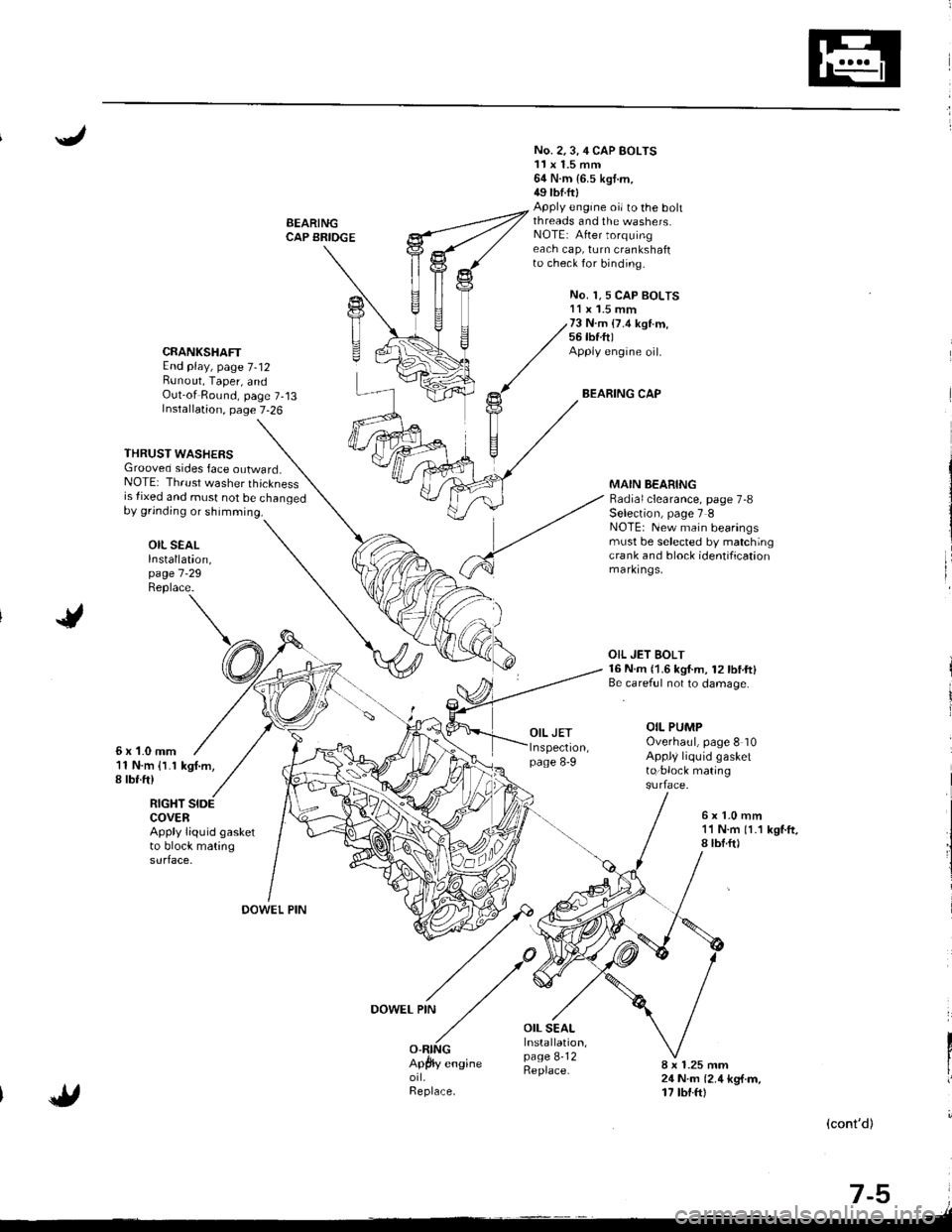
BEARINGCAP BRIOGE
No. 2.3,4 CAP BOLTS11x 1.5 mm64 N.m {6.5 kgt.m,49 tbtftlApply engine oi/ to the bohthreads and the washers.NOTE: After torquingeach cap, turn crankshaftto check for binding.
No. 1,5 CAP BOLTS11 x '1.5 mm73 N.m (7.4 ksl.m,56 tbf.ft)Apply engine oil.
BEARING CAP
CRANKSHAFTEnd play, page 7-12Bunout, Taper, andOut-of Round, page 7-13Installation, page 7-26
THRUST WASHERSGrooved sides face outward_NOTE: Thrust washer thicknessis {ixed and must not be changedby grinding or shimming.
OIL SEALInstallation,page 7 -29
Replace.
MAIN BEARINGRadial clearance, page 7-8Selection, page 7 INOTE: New main bearingsmust be selected by matchingcra nk and block identificationmarkrngs,
6x1-0mm11 N.m {l.1 kgf.m,I rbr.ft)
OIL JET BOLT16 N.m {1.6 kgf.m, 12lbtft}Be.careful not to damage.
OIL PUMPOverhaul, page 8 10Appl/ liquid gasketto:block mating
RIGHT SIDECOVERApply liquid gasketto block matingsurface.
6x1.0mm11 N.m 11.1 kgf.ft,8lbf.ft)
OOWEL PIN
DOWEL PIN
OIL SEALInstallation,page 8-12Replace.8 x 1.25 mm24 N.m {2.4 kg{.m,17 tbt.ftl
(cont'd)
-,tr
t-9 i.lt
Page 152 of 1681
/
li
l
Main Bearings
Clearance
2.
3.
1.
4.
To check main bearing-to-iournal oil clearance,
remove the main caps and bearing halves.
Clean each main iournal and bearing half with a
clean shop towel.
Place one strip of plastigage across each main iour-
na l-
NOTE: lf the engine is still in the car when you bolt
the main cap down to check clearance, the weight
of the crankshaft and flywheel will flatten the plasti'
gage further than just the torque on the cap bolt,
and give you an incorrect reading. For an accurate
reading, support the crank with a jack under the
counterweights and check only one bearing at a
trme.
Reinstall the bearing caps and cap bridge (B18C1,
B18C5 engines only)then torque the bolts.
Bl8Bl engine: 77 N'm (7.8 kgt.m.56lbf.ft)
B18Cl,818C5 engines:
No. 1,5 cap bolts 73 N.m (7.4 kgf.m,56lbnftl
No. 2. 3, 4 cap bolts 64 N.m {6.5 kgf m. 49 lbf ftl
NOTE: Do not rotate the crankshaft during inspec-
tro n.
Remove the cap bridge (818C1, 818C5 engines
only), caps and bearings again, and measure the
widest part of the plastigage.
Main Bearing-to-Journal Oil Clearance:
Standard lNew):
No. 1, 2, 4, 5: 0.024 - 0.042 mm
10.0009 -0.0017 in)
Service Limit:0.050 mm (0.0020 in)
No.3:0.030 - 0.048 mm
10.0012 - 0.0019 inl
Service Limit:0.060 mm {0.0024 inl
PLASTIGAGE STRIP
lf the plastigage measures too wide or too narrow,
{remove the engine if it's still in the car), remove the
crankshaft, and remove the upper half of the bear-
ing. lnstall a new, complete bearing with the same
color code (select the color as shown in the right
column), and recheck the clearance.
CAUTION: Do not file, shim. or scrape the bearings
or the caps to adiust clearance.
lf the plastigage shows the clearance is still incor-
rect, try the next larger or smaller bearing (the color
listed above or below that one), and check again.
NOTE: lf the oroDer clearance cannot be obtained
by using the appropriate larger or smaller bearings.
reolace the crankshaft and start over.
Selection
CAUTION: lf the codes ale indecipherable because of
an accumulation oI dirt and dust, do not scrub them
with a wire bru6h or scraper. Clean lhem only with sol-
vent or detergent.
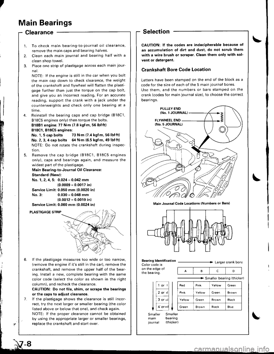
Crankshaft Bore Code Location
Letters have been stamped on the end of the block as a
code for the size of each of the 5 main iournal bores
Use them, and the numbers or bars stamped on the
crank {codes for main journal size), to choose the correct
Dean nqs,
FLYWHEEL END
Main JouhalCode Locations (Numbe.s or Bars)
Bearing ldentif ic.tionColor code ison the edge ofthe bearing.
Larger crank bore
acD
"""""""" Smallerbearingithicker)
Green
Elack
B'ownBlackElue
Smaller Smallermain bearingjournal lthacker)
Page 157 of 1681
NOTE:
. Clean the crankshaft oil passages with pipe cleanersor a suitable brush.
. Check the keyway and threads.
Alignment
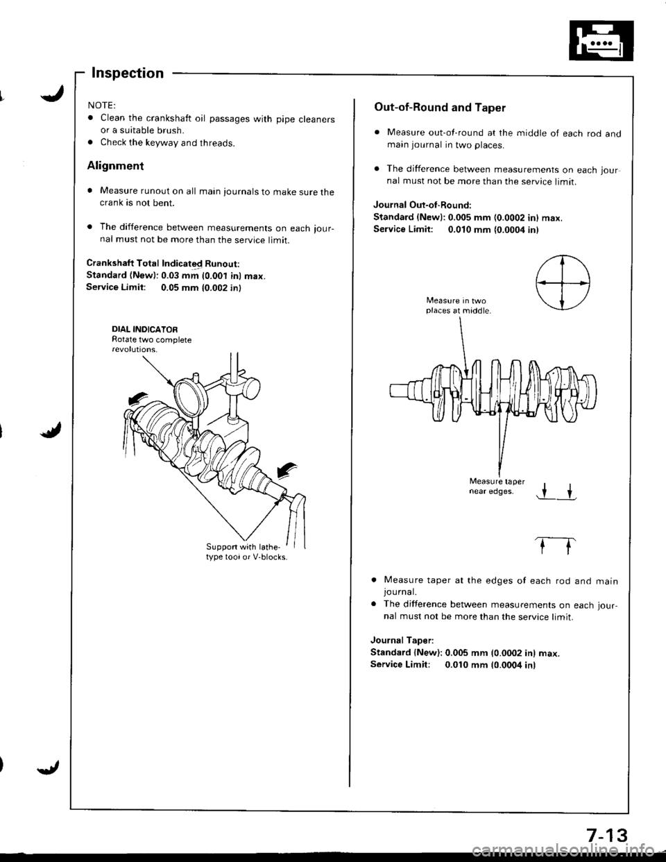
. Measure runout on all main journals to make sure thecrank as not bent.
. The difference between measurements on each ,our-nal must not be more than the service limit.
Crankshaft Total Indicated Runout:
Standard (New): 0.03 mm (0.001 inl max.Service Limit: 0.05 mm 10.002 in)
DIAL INDICATORRotate two complete
Suppon with lathe-type toolor V-blocks.
Out-of-Round and Taper
. Measure out-of-round at the middle of each rod andmain journal in two places.
. The difference between measurements on each jour
nal must not be more than the service limit.
Journal Out-oI-Round:
Standard {Newl:0,005 mm (0.0002 inl max.
Service Limit: 0,010 mm {0.0004 inl
places at middle.
Measure tapernear edges..r +
. Measure taper at the edges of each rod
JOUrnal.. The difference between measurements on
nal must not be more than the service limit.
Journal Taper:
Standard {New): 0.005 mm (0.0002 in) max.
Service Limit: 0.010 mm 10.0004 inr
and matn
each Jour-
7-13
Page 158 of 1681
Cylinder Block
Inspection
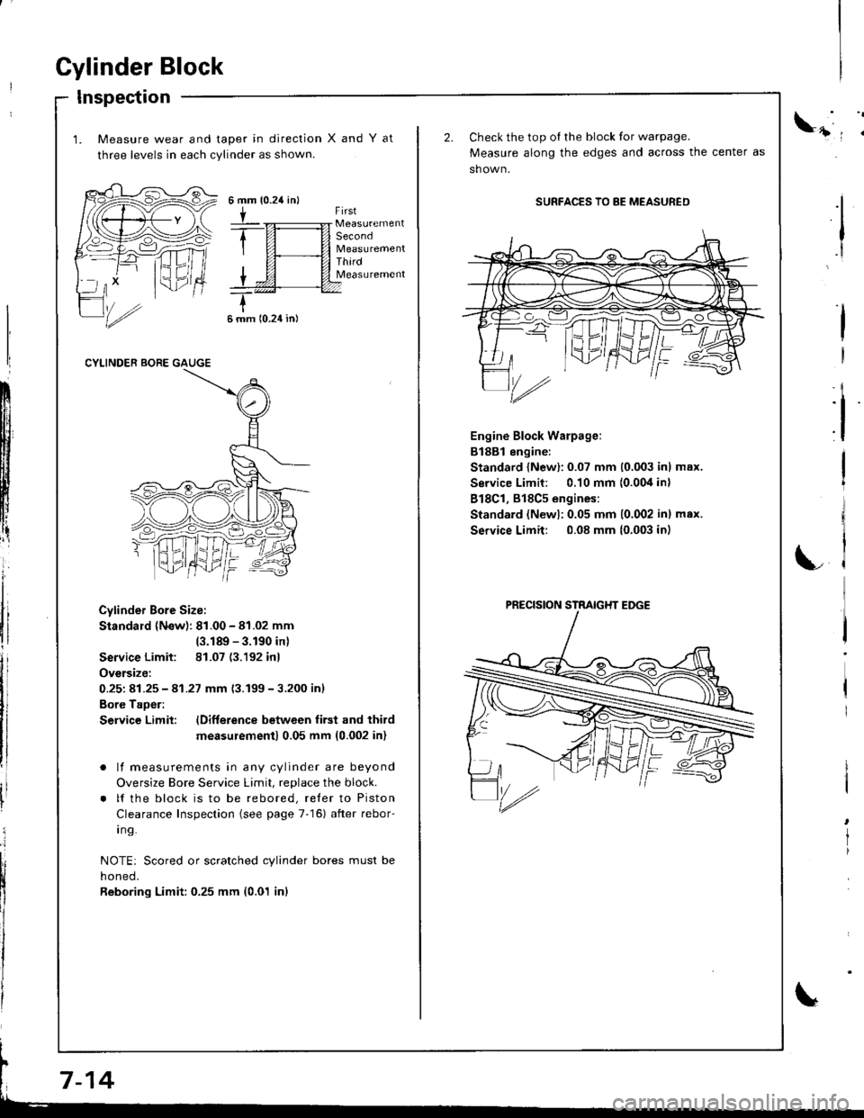
1. Measure wear and taper in direction
three levels in each cylinder as shown.
XandYat
{0.24 in}6mm
tFirst
Second
ThirdMeasurement
6 mm 10.24 in)
CYLINDER BORE GAUGE
Cylinder Bore Size:
Standard (N€w): 81.00 - 81.02 mm
(3.189 - 3.190 inl
Service Limit: 81.07 (3.192 inl
Oversize:
0.251 81.25 - 41.27 mm 13.199-3.200 inl
Bore Taoer:
S€rvice Limit: lDifference betwcen first and third
measu;ement) 0.05 mm (0.002 inl
. lf measurements in any cylinder are beyond
Oversize Bore Service Limit, replace the block.
. lf the block is to be rebored, reler to Piston
Clearance Inspection (see page 7-16) after rebor-
I ng.
NOTE: Scored or scratched cylinder bores must be
noneo,
Reboring Limit: 0.25 mm (0.01 inl
ll
:i
I
I
Check the top oI the block for warpage.
Measure along the edges and across the center as
sh own.
SURFACES TO 8E MEASURED
Engine Block Warpage:
B188l engine:
Standard {New}: 0.07 mm (0,003 inl max.
Service Limit: 0.10 mm {0.004 in)
818C1, 818C5 engines:
Standard (Newl:0.05 mm 10.002 inl max.
Service Limit: 0.08 mm (0.003 in)
I
I
rl
LC
'/rz
PRECISION STRAIGHT EDGE
Page 159 of 1681
11
Bore Honing
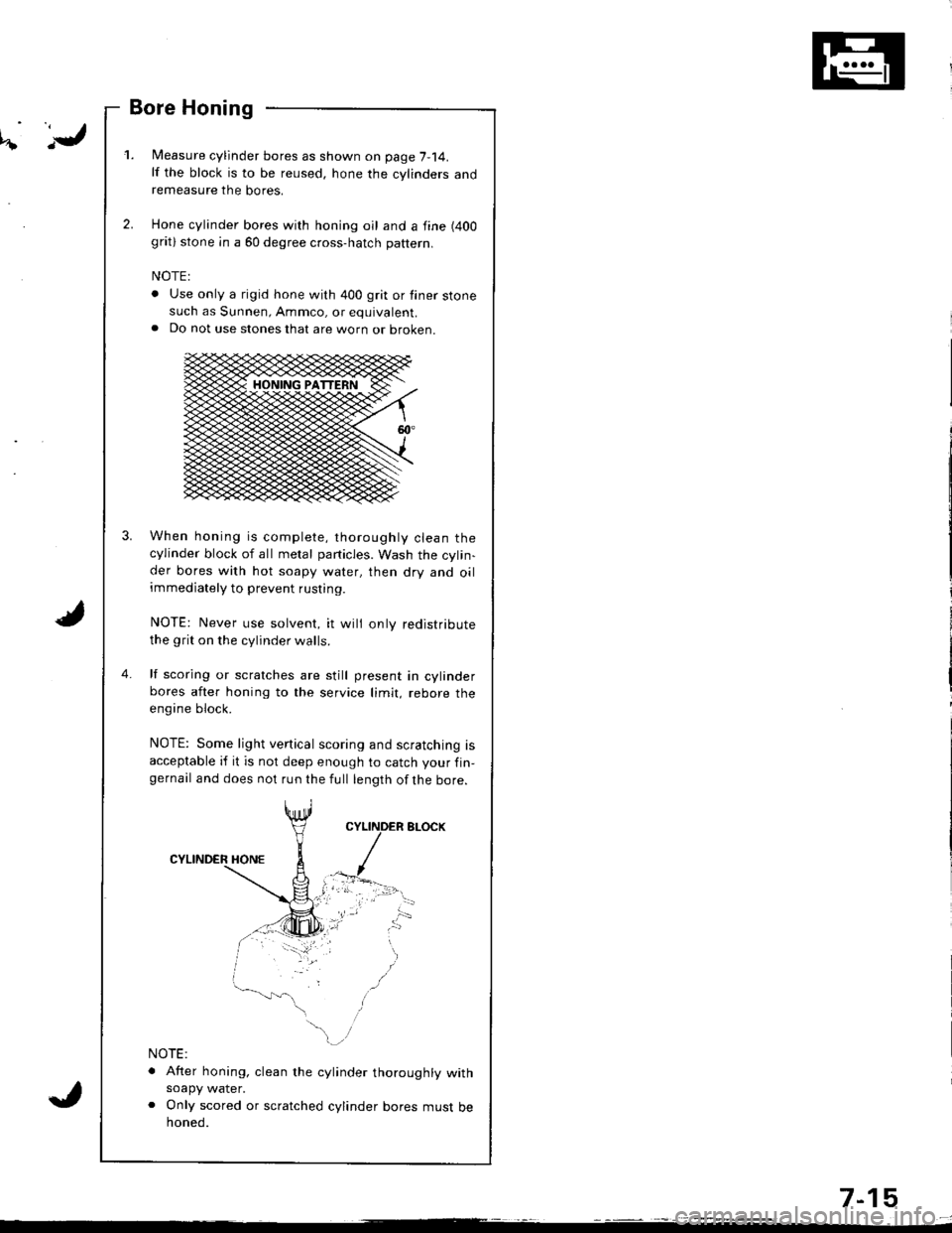
l/easure cylinder bores as shown on page 7-14.lf the block is to be reused, hone the cylinders andremeasure the bores.
Hone cylinder bores with honing oil and a fine (400
grat) stone in a 60 degree cross-hatch pattern.
NOTE:
. Use only a rigid hone with 400 grit or finer stonesuch as Sunnen, Ammco, or equivalent.a Do not use stones that are worn or oroKen.
When honing is complete, thoroughly clean thecylinder block of all melal particles. Wash the cylin-der bores with hot soapy water, then dry and oilimmediately to prevent rusting.
NOTE: Never use solvent, it wili only redistribute
the grit on the cylinder walls.
lf scoring or scratches are still present in cylinderbores after honing to the service limit, rebore theengine block.
NOTE: Some light vertical scoring and scratching isacceptable if it is not deep enough to catch your fin-gernail and does not run the full length ofthe bore.
NOTE:
. After honing, clean the cylinder thoroughly withsoapy water.o Only scored or scratched cylinder bores must behoned.
4.
7-15
Page 160 of 1681
Pistons
Inspection
1. Check the piston lor distortion or cracks.
NOTE: lf the cylinder is bored, an oversized piston
musl be used.
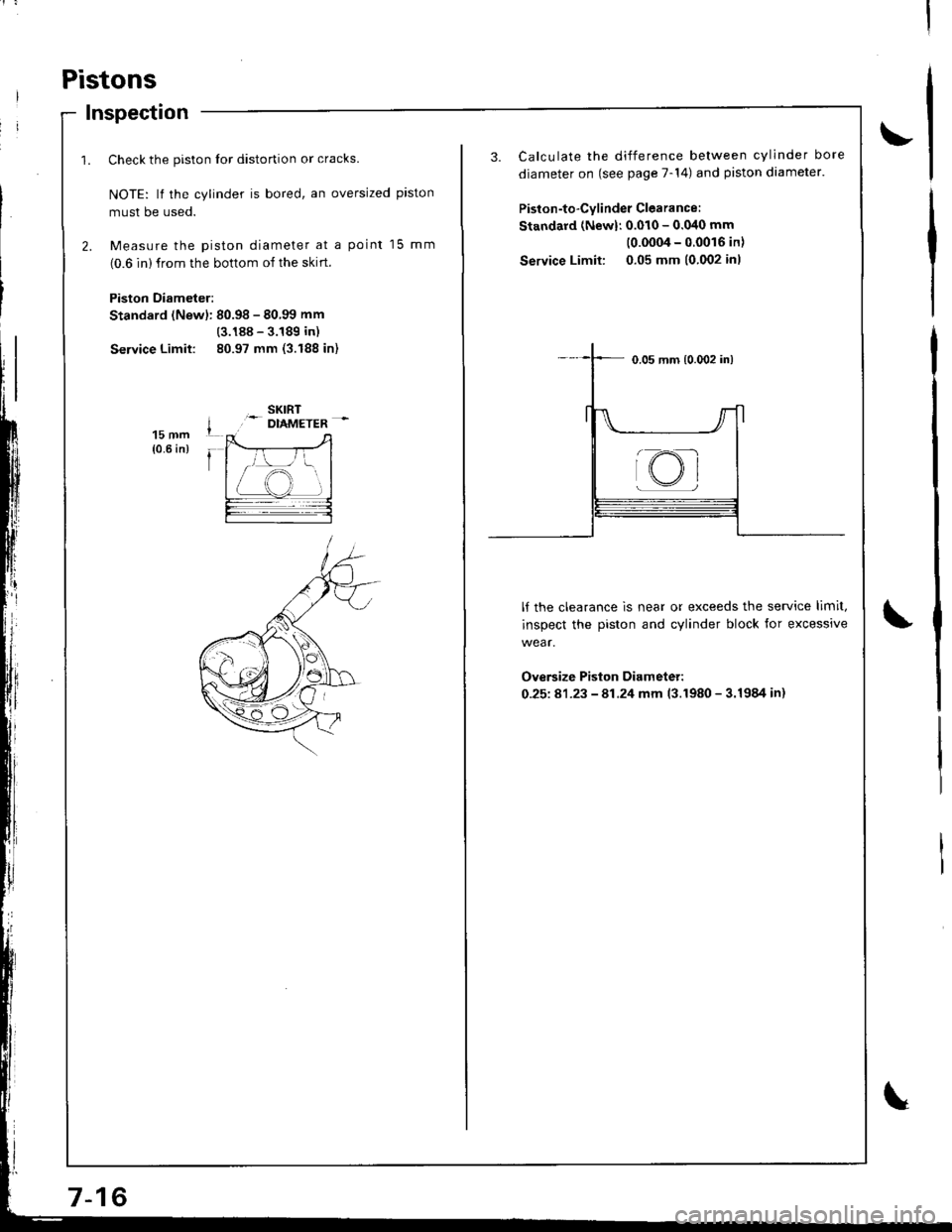
2. Measure the piston diameter at a point 15 mm
(0.6 in) from the bottom of the skrrt.
Piston Diameter:
Standard (Newl: 80.98 - 80.99 mm
(3.188 - 3.189 in)
Service Limit: 80.97 mm (3.188 in)
15 mm{0.6 in)
3. Calculate the difference between cylinder bore
diameter on (see page 7-14) and piston diameter.
Piston-to-Cylinder Clearance:
Standard (Newl: 0.010 - 0.040 mm
(0.0004-00016in)
Service Limit: 0.05 mm (0.002 inl
lf the clearance is near or exceeds the service limit,
inspect the piston and cylinder block for excessive
wear.
Ove6ize Piston Diameter:
0-25181-23 - 81.24 mm 13.1980 - 3.1984 in)
@
Page 164 of 1681
Piston Rings
Replacement
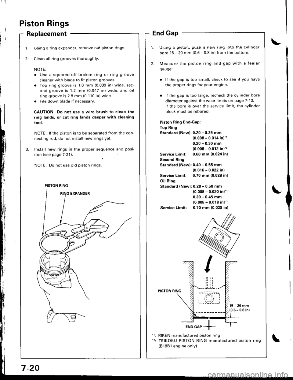
Using a ring expander, remove old piston rlngs.
Clean all ring grooves thoroughly.
o Use a squared-ofl broken ring or ring groove
cleaner with blade to fit piston grooves.
. lop ring groove is 1.0 mm (0.039 in) wide, sec
ond groove is 1.2 mm (0.047 in) wide, and oil
ring groove is 2.8 mm (0.110 in) wide.
. File down blade if necessary.
CAUTION: Do not use a wire brush to clean the
ring lands, or cut ring lands deeper with cleaning
tool.
NOTE: lf the piston is to be separated from the con
necting rod, do not install new rings yet.
Install new rings in the proper sequence and posa-
tion (see page 7 21).
Do not use old piston rings.
PISTON RING
End Gap
Using a piston, push a new ring into the cvlinder
bore 15 - 20 mm 10.6 0.8 in) f rom the bottom.
2. N,4easure the piston ring end gap with a feeler
gauge:
lf the gap is too small, check to see if you have
the proper rings for your engine.
. lf the gap is too large, recheck the cylinder bore
diameter against the wear limits on page 7-13.
lf the bore is over the service limit, the cylinder
block must be rebored.
Piston Ring End-Gap:
Top Ring
Standard (New):0.20 - 0.35 mm
(0.008 - 0.014 inl'1
0.20 - 0.30 mm
{0.008 - 0.012 in}''�
Service Limit: 0.60 mm {0.024 in)
Second Ring
Standard {New): 0.40 - 0.55 mm
{0.016 - 0.022 inl
Service Limit: 0.70 mm {0.028 inl
Oil Ring
Standard (New): 0.20 - 0.50 mm
10.008 - 0.020 in)'r
0.20 - 0.45 mm
(0.008 - 0.018 in)''�
Service Limit: 0.70 mm (0.028 in)
PISTON RING
15-20mm{0.6 - 0.8 in)
RIKEN manufactured piston ring
TEIKOKU PISTON RING manufactured piston ring
(B 1881 engine only)
Page 170 of 1681
t'
Crankshaft
lnstallation
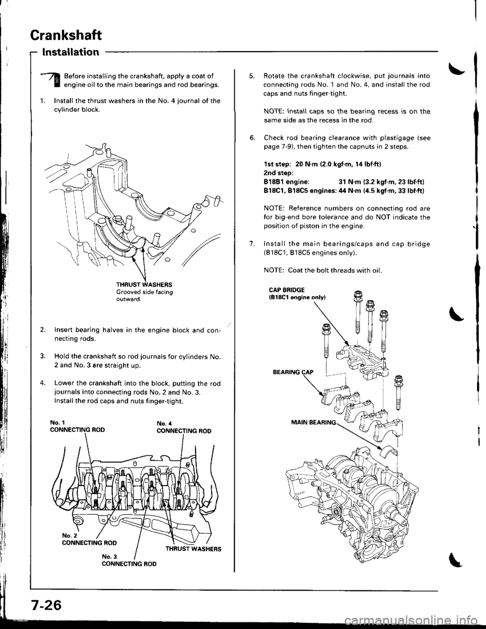
-Q Before installing the crankshaft, apply a coat of
E engine oilto the main bearings and rod bearings.
1. lnstall the thrust washers in the No. 4 iournal of the
cylinder block.
Grooved side facingoutwaro,
Insert bearing halves in the engine block and con-
necflng roos.
Hold the crankshaft so rod journals for cylinders No.
2 and No.3 sre straight up.
Lower the crankshaft into the block, putting the rod
iournals into connecting rods No.2 and No.3.
Installthe rod caps and nuts finger-tight.
No. 1No. 4
CONNECTING ROO
7-26
1.
Rotate the crankshaft clockwise, put journals into
connecting rods No. 1 and No.4, and install the rod
caps and nuts tinger-tight.
NOTEI lnstall caps so the bearing recess is on the
same side as the recess in the rod.
Check rod bearing clearance with plastigage (see
page 7-9), then tighten the capnuts in 2 steps.
lst step: 20 N.m (2.0 kgf m, 14 lbf.ftl
2nd step:
81881 engine:31 N.m (3.2 kgf.m, 23 lbf.ftl
818C1,818C5 enqines:44 N.m (4.5 kgf.m,33 lbt.ftl
NOTE: Reference numbers on connecting rod are
tor big-end bore tolerance and do NOT indicate the
position of piston in the engine.
Install the main bearings/caps and cap bridge(818C1, 818C5 engines only).
NOTE: Coat the bolt threads with oil
CAP BRIDGE{B18Cl engine onlyl
BEARING
MAIN BEARING
fi
U
t{
T
!+
T1
Page 171 of 1681
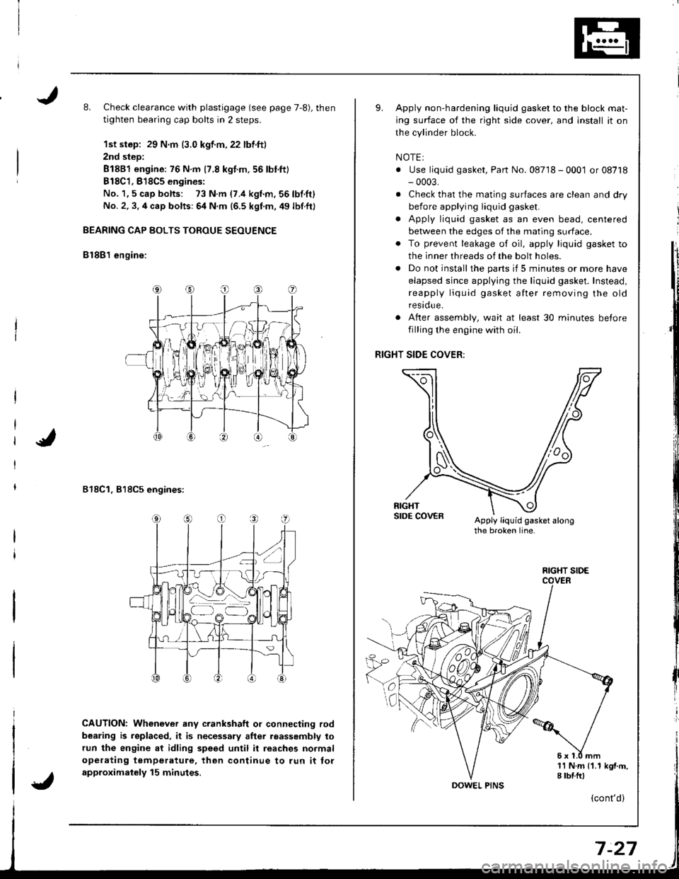
L Check clearance with plastigage (see page 7,8), then
tighten bearing cap bolts in 2 steps.
1st step: 29 N.m (3.0 kgf.m,22 lbf.ft)
2nd step:
81881 engine: 76 N.m 17.8 kgt.m.56 lbnft)
B18C1,818C5 engines:
No. 1,5 cap bolts: 73 N.m (7.4 kgnm,56lbf.ft)
No. 2, 3. 4 cap bolts: 64 N.m (6.5 kgf.m, 49 lbf.ft)
BEARING CAP BOLTS TOROUE SEOUENCE
B lSB'l engine:
818C1, 818C5 engines:
CAUTION: Whenever any crankshaft o. connecting rod
bearing is replaced, it is necessary after reassembly to
run the engine at idling speed until it reaches normal
opelating temperature, then continue to run it tor
approximalely 15 minutes.
Apply non-hardening liquid gasket to the block mat-
ing surface of the right side cover, and install it on
the cylinder block.
NOTEI
. Use liquid gasket, Part No. 08718 - 0001 or 08718- 0003,
. Check that the mating surfaces are clean and dry
before applying liquid gasket.
. Apply liquid gasket as an even bead, centered
between the edges of the mating surface.
. To prevent leakage of oil, apply liquid gasket to
the inner threads of the bolt holes.
. Do not install the parts if 5 minutes or more have
elapsed since applying the liquid gasket. Instead,
reapply liquid gasket after removing the old
residue.
After assembly, wait at least 30 minutes betore
filling the engine with oil.
RIGHT SIDE COVER:
Apply liquid gasket alongthe broken line.
o
a
1l N.m {1.1 kgf.m,I tbf.frl
FIGHT SIDE
(cont'd)
Page 172 of 1681
Crankshaft
Installation (cont'd)
I
I
t
l;I
I
fi,
\
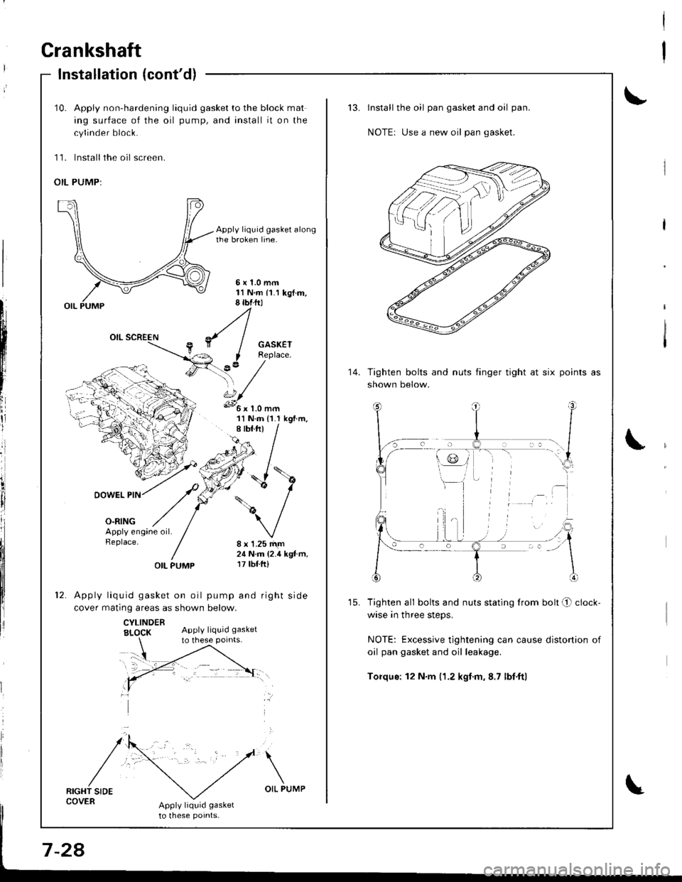
10. Apply non-hardening liquid gasket to the block mat
ing surface of the oil pump, and install it on the
cylinder block.
11. lnstall the oil screen.
OIL PUMP:
Apply liquid gasket alongthe broken line.
5x1.0mm11N.m 11.1 kgt.m,8 tbtftl
GASKETReplace.
?,' /'\, /s.../
11 N.m {1.I kgf.m,
DOWEL PIN
o-ntNG
/\
/
':'
Apply engine oil.Replace.8 x 1.25 r\m24 N.m (2.4 kgt.m,17 tbf.ft)OIL PUMP
Apply liquid gasket on oil pump and right side
cover matinq areas as shown below.
CYLINDERBI_OCK Apply liquid gasket
RIGHT SIDECOVERApply liquid gasket
to lhese potnts-
to these points.
Install the oil pan gasket and oil pan.
NOTEr Use a new oil pan gasket.
Tighten bolts and nuts finger tight at six
shown below.
points as
Tighten all bolts and nuts stating from bolt O clock-
wise in three steps.
NOTE: Excessive tightening can cause distortion of
oil pan gasket and oil leakage.
Torqus: 12 N.m (1.2 kgf.m,8.7 lbf'ftl
14.