lock HONDA INTEGRA 1998 4.G Owner's Guide
[x] Cancel search | Manufacturer: HONDA, Model Year: 1998, Model line: INTEGRA, Model: HONDA INTEGRA 1998 4.GPages: 1681, PDF Size: 54.22 MB
Page 193 of 1681
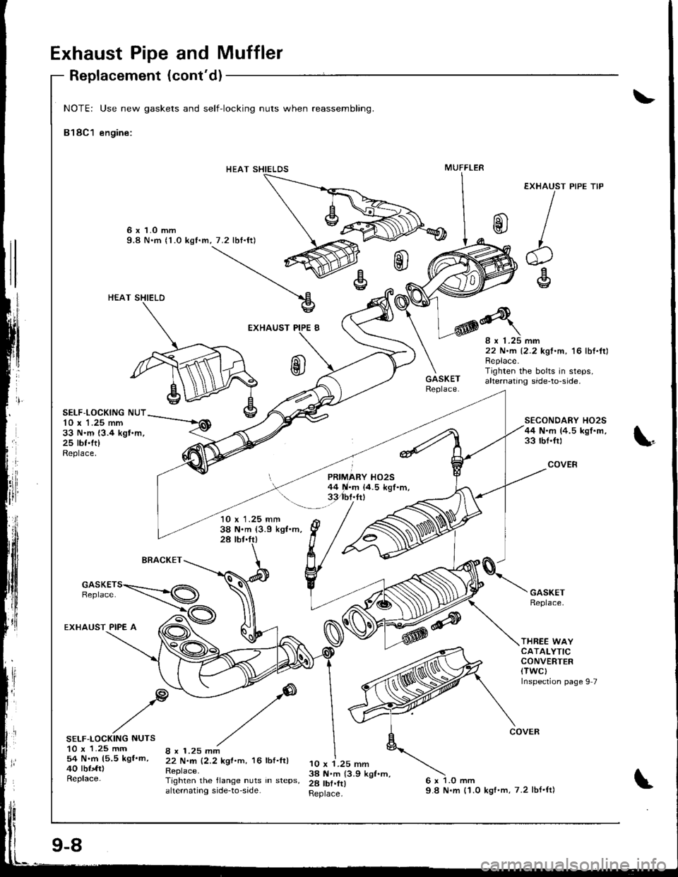
Exhaust Pipe and Muffler
EXHAUST
b
'+l\v
rl
IIrl
NOTE: Use new gaskets and self-locking nuts when reassembling.
818C1 engine:
6 x 1.O mm9.8 N.m (1.0 kgf.m, 7.2 lbf.ft)
HEAT SHIELD
EXHAUST PIPE 8
Replacement (cont'd)
SELF,LOCKING NUT10 x 'l .25 mm33 N.m {3.4 kgt.m,25 tbf.ft)Replace.
PIPE TIP
BRACKET
10 x 1.25 mm38 N.m (3.9 kgl.m,28 tbt.fr)
8 x 1.25 mm22 N.m 12.2 kgt.m, '16 lbI.ft)Replace.Tighren the bolts in steps,alternating side-to-side.
SECONDARY HO2S44 N.m (4.5 kgI.m,33 rbf.fr)
COVER
THREE WAYCATALYTICCONVERTER(TWCI
Inspection page 9 7
EXHAUST PIPE A
SELF-LOCKING NUTS10 x 1.25 mm54 N.m 15.5 kgf.m,40 tbfdr)Replace-
8 x 1.25 mm22 N.rn 12.2 kgf.m, 16 lbf.ft)Replace.Tighten the flange nuts in steps,ahernating side-to-side.
10 x 1.25 mm3a N.m {3.9 kgf.m,28 tbf.fr)Replace.
HEAT SHIELDSMUFFLER
9-8
9.8 N.m {'1.0 kgf'm,7.2 lbf'ft)
Page 194 of 1681
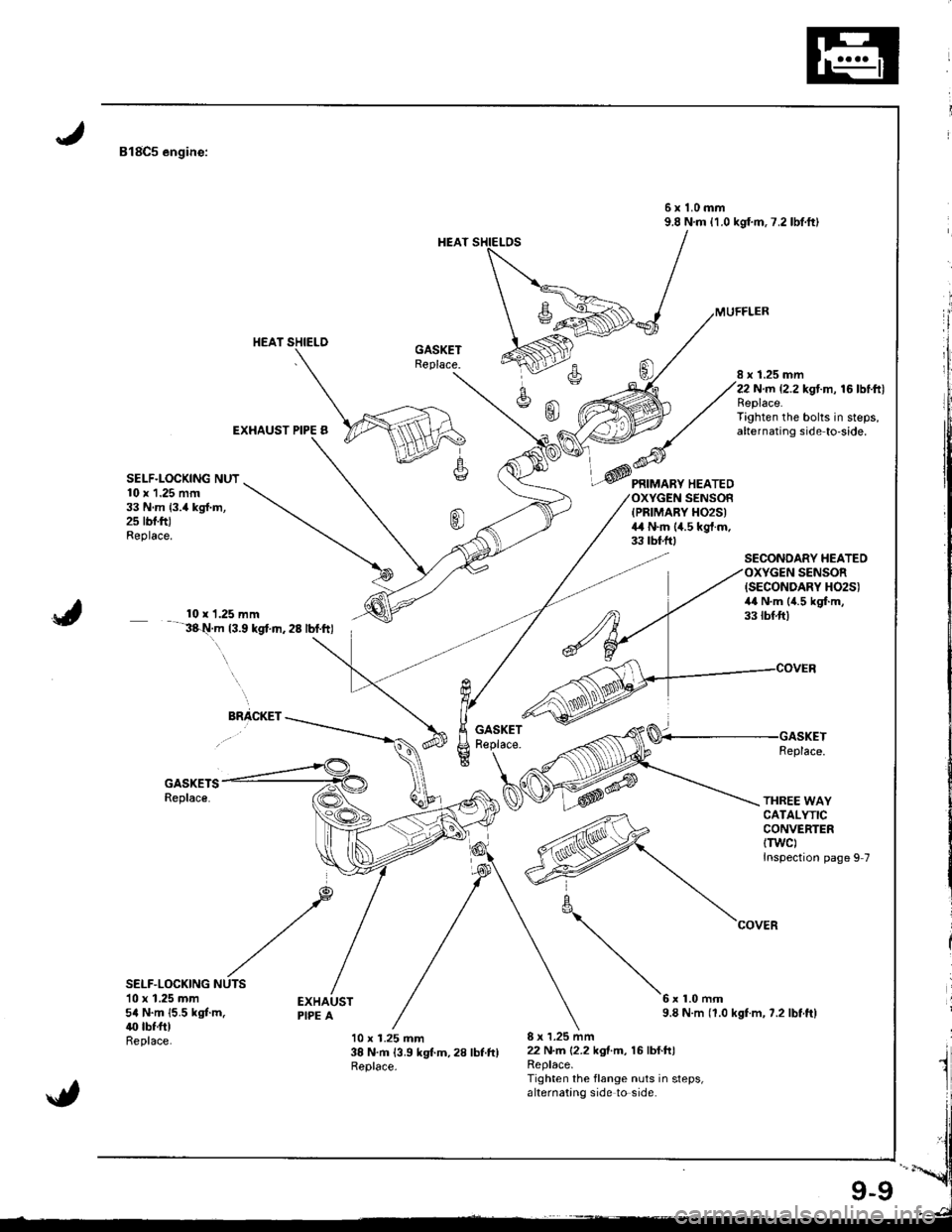
818C5 engine:
6x1.0mm9.8 N.m {1.0 kgf.m.7.2lbtft)
EXHAUST PIPE B
8 x 1.25 mm22 N.rn {2.2 kgt.m, 16 lbtftlReplace.Tighten the bolts in steps,alternating side to'side.
SELF.LOCKING NUT10 x 1.25 mrn33 N.m {3.4 kgl.m,2s rbf.ftJReplace.
PRIMARY HEATEDSENSOFIPRIMARY H02S)4,1 N.m (4.5 kgt.m.33 tbf.ftt
SECONDARY HEATEOSENSOR
J
{SECONDARY H02S)4,0 N.m (4.5 kgf.m,33 tbf.ft)10 x 1.25 mm3&t!.m t3.9 kgt.n.28 lbf.ftl. \
ElacKEr -*_____GASKETReplace-
GASKETSReplace.
Replace.
THREE WAYCATALYTICCONVERTERtTwc)Inspection page 9 7
SELF.LOCKING10 x 1.25 mm5a N.m {5.5 kgt m.40 tbf.ftlReplace.
6x1.0mm9.8 N.m (1.0 kgf.m, ?.2 lbt.ftl
10 x 1.25 mm38 N.m 13.9 kgt m,28 lbt.ftlReplace.
8 x 1.25 mm22 N.m 12.2 kgtm, 16lbf.h)Replace.Tighten the flange nuts in steps,alternating side to side.
_@
\
Page 200 of 1681
Radiator
Engine Coolant Refilling and Bleeding
CAUTION: When pouring engine coolant, be sure to shut
th6 relay box lid and not to l€t coolant spill on th6 el€c-
trical parts or the paint. lf any coolant spills, rinse it off
immediately.
1. Slide the heater temDerature control lever to maxi-
mum heat.
Make sure the engine and radiator are cool to the
touch.
2. Remove the radiator cap.
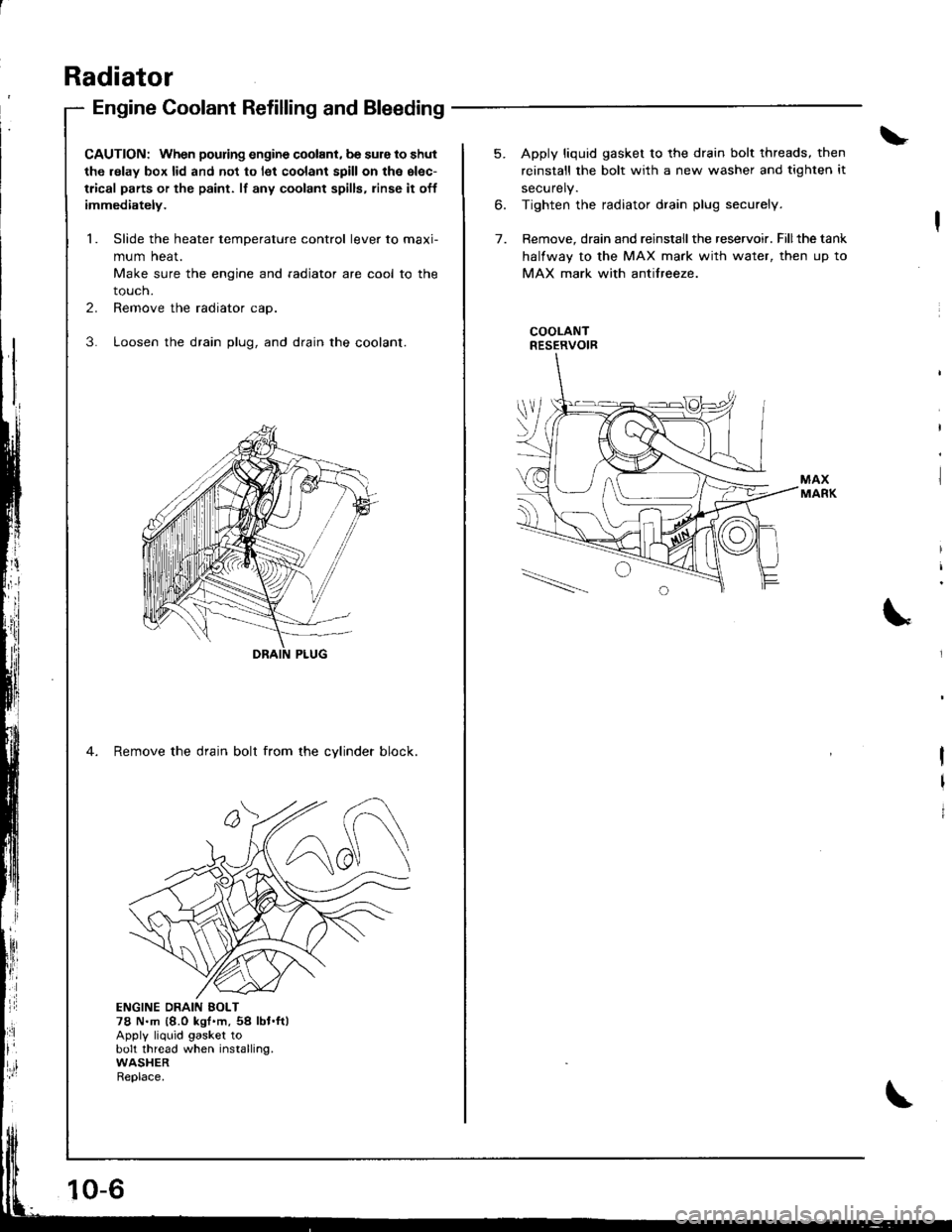
3. Loosen the drain plug, and drain the coolant.
4. Remove the drain bolt from the cvlinder block.
ji
Ii'
l:ll
ENGINE DRAIN EOLT78 N.m {8.0 kgt'm,54 lbt.ft)Apply liquid gasket tobolt thread when installing.WASHERReplace.
10-6
5. Apply liquid gasket to the drain bolt threads, then
reinstall the bolt with a new washer and tighten it
securely.
6. Tighten the radiator drain plug securely.
7. Remove, drain and reinstall the reservoir. Fillthe tank
halfway to the MAX mark with water, then up to
MAX mark with antifreeze.
COOLANTRESERVOIR
I
I
I
Page 205 of 1681
Inspection
Remove the timing belt (81881 engine: see page 6-10, B'l8Cl,818C5 engines: see page 6-48).
Tu.n the water pump pulley counterclockwise.Check that it turn freely.
Check for sign6 of seal leakage.
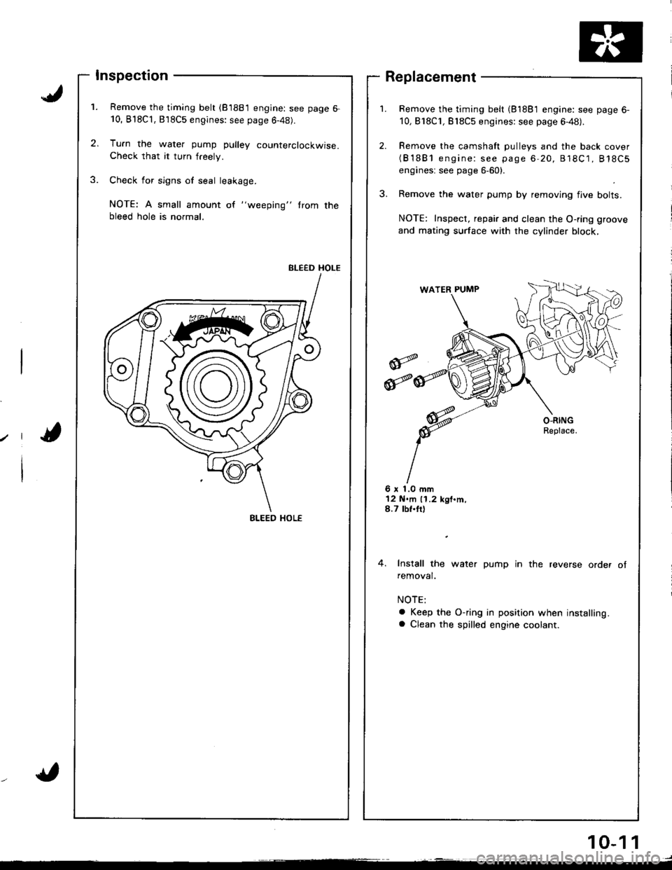
NOTE: A small amount of "weeping" trom thebleed hole is normal.
BLEED HOLE
Remove the timing belt (81881 engine: see page 6-
10,818C1, Bl8C5 engines: see page 6-48).
Remove the camshaft pulleys and the back cover(B'1881 engine: see page 6-20, 818C1, 818C5
engines: see page 6-60).
Remove the water pump by removing flve bolts.
NOTE: Inspect, repair and clean the O-ring groove
and mating surface with the cylinder block,
Replacement
6 x 1.0 mm12 N.m 11.2 kgt.m,8.7 tbf.tt)
4. Install the water pump in the reverse order ofremoval.
a Keep the O-ring in position when installing.a Clean the spilled engine coolant.
BLEED HOL€
10-1 1
Page 241 of 1681
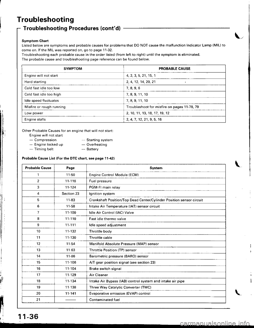
Troubleshooting
Troubleshooting Procedures (cont'd)
Symptom Chart
Listed below are symptoms and probable causes for problems that DO NOT cause the malfunction Indicator Lamp (MlL) to
come on. lf the MIL was reported on, go to page 11-32.
Troubleshooting each probable cause in the order listed (from left to right) until the symptom is eliminated.
The probable cause and troubleshooting page relerence can be found below.
Other Probable Causes for an engine that will not start:
Engine will not sta rt- Compression- Engine locked up- Timing belt
\_
- Starting system- Overheating- Battery
'4,
It
Probable Cause List (For the DTC chart. see page 11-421
Probable CausePageSystem
111-50Engine Control Module (ECM)
211118Fuel pressure
311-124PGM-Fl main relay
4Section 23lgnition system
51 1-83Crankshaft Position/ToD Dead Center/Cylinder Position sensor circuit
11-58Intake Air Temperature (lAT) sensor circuit
71 '�t- 100ldle Air Control (lAC) Valve
811110Fast idle thermo valve
I11lllldle speed adjustment
'1011-132Throttle body
111 1-130Throttle cable
1211-54lvlanifold Absolute Pressure {MAP) sensor
IJ1163Throttle Position {TP) sensor
1411-86Barometric pressure (BARO) sensor
1 '1 106A/T gear position signal {see section 23)
16'1 1 104Brake switch signal
1711 129Air Cleaner
181 1- 134Intake Air Bypass {lAB} control system and intake air pipe
19'1 1 138Three Way Catalytic Convener (TWC)
2011-141Evaporative emission (EVAP) control
21Contaminated fuelll ll 21 | - | cont"-in"t"o tu"
11 l-
I
,l 11-36
-
SYMPTOMPROBABLE CAUSE
Engine will not stan4, 2, 3,5, 21, 15, 1
Hard starting2, 4, 12, 14,20,21
Cold fast idle too low
Cold fast idle too high7, 8, 9, 11, r0
ldle speed fluctuates7,8,9,11,10
Misfire or rough runningTroubleshoot for misfire on pages 11-78,79
Low power2, 10,'t1, 13, 14, 17, 19, 12
Engine stalls2, 4,1 , 12,21,9, 5, 16
Page 245 of 1681
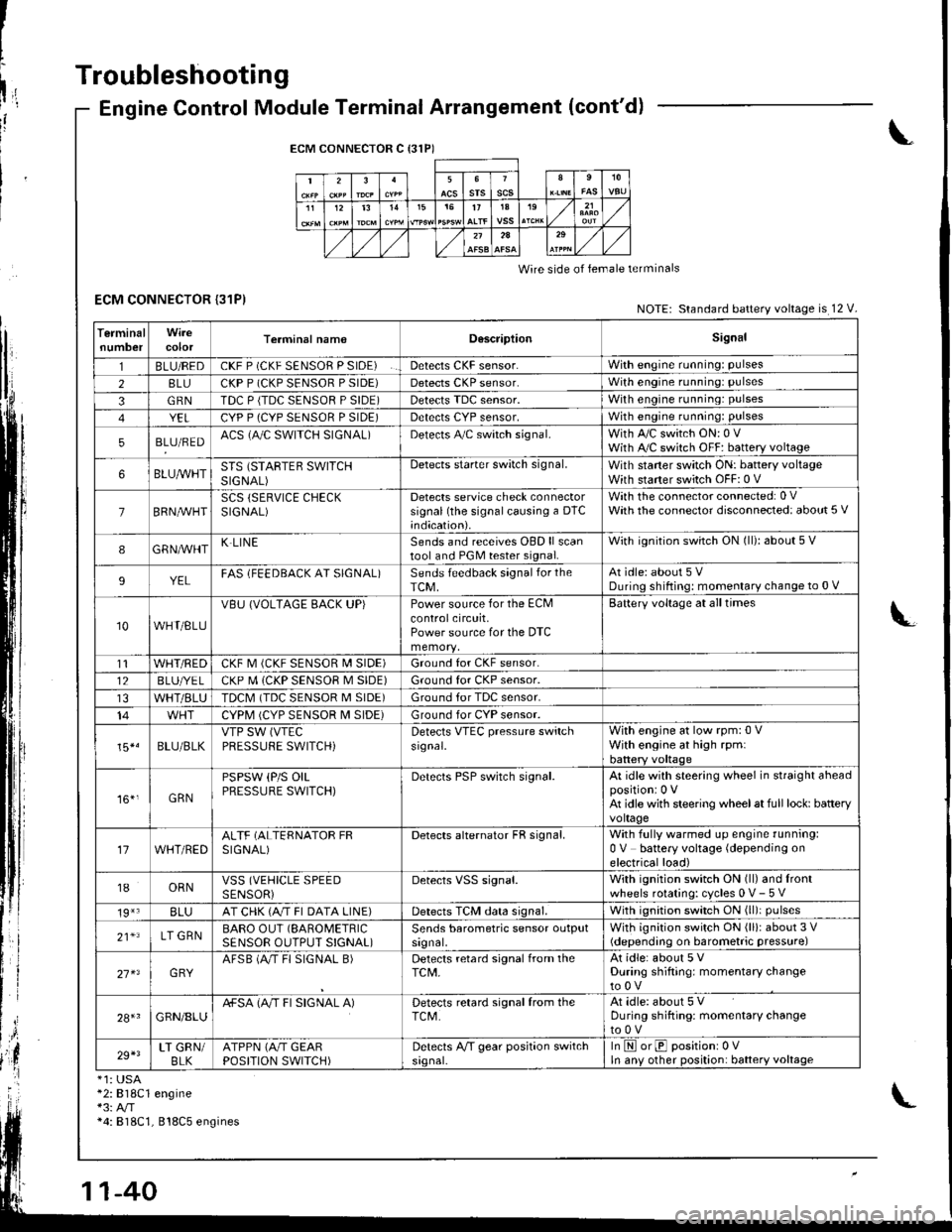
I
t
h,,l,!
il
Troubleshooting
ECM CONNECTOR {31P)
Engine Control Module Terminal Arrangement (cont'd)
ECM CONNECTOR C {31P)
235srsscs1112t31515t71A19
2A
Wire side of lemale terminals
NOTE: Standard battery voltage is 12 V.
TerminalnumbercolorTerminal namoD6scriptionSignal
1BLU/REDCKF P (CKF SENSOR P SIDE)Detects CKF sensor.With engine running: pulses
28LUCKP P (CKP SENSOR P SIDE)Detects CKP sensor.With engine running: pulses
3GRNTDC P {TDC SENSOR P SIDE)Detects TDC sensor,With engine running: pulses
YELCYP P (CYP SENSOR P SIDE)Detects CYP sensor,With engine running: pulses
5BLU/REDACS (AJC SWITCH SIGNAL)Detects A,/C switch signal.With A,/C switch ON: 0 VWith A,/C switch OFF: battery voltage
6BLUA/VHTSTS (STARTEB SWITCHSIGNAL)
Detects starter switch signal.With staner switch ON: battery voltageWith starter switch OFF: 0 V
7BRN,AiVHTSCS (SERVICE CHECKSIGNAL)Detects service check connectorsignal (the signalcausing a DTC;ndication).
With the co n nector con nected: 0 VWath the connector disconnected: about 5 V
8GRNAVHTK LINESends and receives OBD ll scantool and PGM tester signal.With ignition switch ON (ll): about 5 V
9YELFAS lFEEDBACK AT SIGNAL)Sends feedback signal for theTCM,At idle: about 5 VDuring shifting: momenlary change to 0 V
10WHT/BLU
VBU (VOLTAGE BACK UP)Power source for the ECMcontrolcircuit,Power source for the DTC
Battery voltage at all times
t1WHT/REDCKF M (CKF SENSOR I\4 SIDE)Ground for CKF sensor.
12BLUI/E LCKP M (CKP SENSOR M SIDE)Ground for CKP sensor.
WHT/BLUTDCM (TDC SENSOR M SIDE)Ground tor TDC sensor.
14CYPM (CYP SENSOR M SIDE)Ground for CYP sensor.
15*.BLU/BLKVTP SW (VTEC
PRESSUFE SWITCH)Detects VTEC pressure switchsr9nal.
With engine at low rpm:0 VWith engine at high rpmlbattery voltaqe
161,GRN
PSPSW (P/S OILPRESSURE SWITCH)Derecls PSP switch signal.At idle with steering wheel in straight aheadpositioni 0 VAt idle with steering wheelat full lock: batteryvoltage
17WHT/REDALTF (ALTERNATOR FRSIGNAL)Detects alternator FR signal.With fully warmed up engine running:0 V battery voltage (depending onelectrical load)
18ORNVSS (VEHICLE SPEEDSENSORiDetects VSS signal.With ignition switch ON (ll) and lrontwheels rotating: cycles 0 V- 5 V
19*3BLUAT CHK (A/T FI DATA LINE)Detects TCM data signal.With ignition switch ON (ll)i pulses
21*LT GRNBARO OUT (SAROMETRIC
SENSOR OUTPUT S!GNAL)Sends barometric sensor outputsrgnal,With ignition switch ON (ll): about 3 V(depending on barometric pressure)
27 x3GRYAFSB (A"/T FI SIGNAL B)Detects retard signal from theTCM,At idle: about 5 VDuring shifting: momentary changeto0V
28+1GRN/8LUA+SA (A/T FI SIGNAL A)Detects retard signal from theTCM.At idle: about 5 VDuring shifting: momentarV changeto0V
29+3LT GRN/BLKATPPN (A/T GEARPOSITION SWITCH)Detects A,/T gear position switchsrgnal-In E orE positionr 0VIn anv other position: battery voltage
*1: USA*2:818C1 engine*3: A/T*4: 818C1, 818C5 engines
Page 283 of 1681
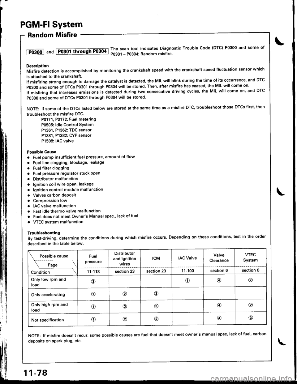
PGM-FI System
Random Misfire
1T0-500 1 a nd Fo-30ittrrousFF0304-lThB scan tool indicates Diagnostic Trouble Code {DTC) P0300 and some of
P0301 - P0304: Random misfire.
Doscription
Misfir; detection is accomplished by monitoring the crankshaft speed with the crankshaft speed fluciuation sensor which
is attached to the crankshsft.
lf misfiring strong enough to damage the catalyst is detected, the MIL will blink during iho time of its occurrence, and DTC
p0300 and some of DTCS p0301 through P0304 will be stor€d. Then, after misfire has ceased, the MIL will come on.
lf misfiring that increases emissions is detected during two consecutive driving cycles, the MIL will come on, and DTC
PO3O0 and some ot DTCS P0301 through P0304 will be stored
NOTE: lJ some of the DTCS listed below are stored at the same time as a misfire DTC, troubleshoot those DTCS first. then
troubleshoot the misfire DTC.
P0171, P0172: Fuel metering
P0505: ldle Control SYstem
P1361, P1362: TDC sensor
P1381. P1382: CYP sensor
P1508: IAC valve
Possible Cause
. Fuel pump insufficient fuel pressure. amount of flow
. Fuel line clogging, blockage, leakage
. Fuel {ilter clogging
a Fuel pressure regulator stuck open
. Distributormallunction
o lgnition coil wire open, leakage
. lgnition control module malfunction
. Valves carbon deposit
a Compression low
. IAC valve malfunction
. Fast idle thermo valve malfunction
o Fuel does not meet Owner's Manual spec., lackotfu€l
. VTEC system malfunction
Troubleshooting
By test-driving, determine the conditions during which misfire occurs. Depending on these conditions, test in the order
described in the table below.
Fuel
pressure
Distributor
and lgnition
wires
tcMIAC ValveValve
Clearance
wEc
System
11118section 23section 231 1- 100section 6section 6
Only low rpm and
loao@o@@
Only acceleratingo@o
Only high rpm and
loado@@@o
Not specificationo@@@@
NOTE: lf misfire doesn't recur, some possible causes arefuel that doesn't meet owner's manual spec, lackoffuel, carbon
deposits on spark plug, etc.
11-78
Page 290 of 1681
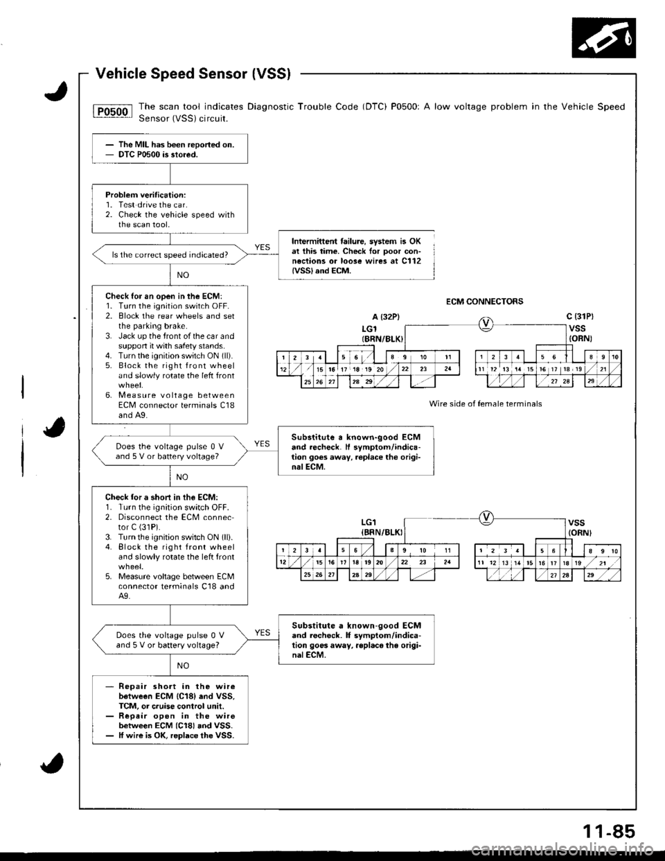
The scan tool indicates Diagnostic Trouble Code (DTC) P0500r A low voltage problem in the Vehicle Speed
Sensor (VSS) circuit.
Intermittent failure, system is OKat this time. Check for ooor con-neciions or loose wires at C112IVSSI and ECM.
ECM CONNECTORS
A (32P)
LGlIBRN/8LK)
c (31Pt
vss{ORN)
Wire side of female terminals
The MIL has been reported on.DTC P0500 is stored.
Probleft veritication:1. Test drive the car.2. Check the vehicle speed withthe scan tool,
ls the correct speed indicated?
Check lor an open in the ECM:1. Turn the ignition switch OFF.2. Block the rear wheels and setthe parking brake.3. Jack up the front of the car andsuppon it with safety stands.4. Turn the ignition switch ON (ll).
5. Block the right front wheeland slowly rotate the left front
6. Measure voltage betweenECM connector terminals C18and A9.
Substitute a known-good ECMand recheck. H symptom/indica-tion goes away, replace tho origi-nalECM.
Does the voltage pulse 0 Vand 5 V or battery voltage?
Check lor a shori in th€ ECM:1. Turn the ignition switch OFF.2. Disconnect the ECM connector C (31P).
3. Turn the ignition switch ON (lli.4. Block the right front wheeland slowly rotate the left front
5. Measure voltage between ECMconnector lerminals C18 andA9.
Substitute a known-good ECMand lecheck. lf symptom/indica-tion goos away. rsplaco the origi-nalECM.
Does the vohage pulse 0 Vand 5 V or battery voltage?
Repair short in the wireb€tween ECM {C18} end VSS,TCM, or cruise control unit.Repeir open in the wirebetween ECM (C18) aod VSS.ff wire is OK, replace the VSS.
ra 17 18 19 20t6 ]t 13r19
LG1{BRN/BLKIvss(ORNI
23563910 1156
12i5r92022 23 2a11 1213 1/tr6ts/zt
25262Aa9,/2724," ,/ ,,:
1 1-85
Page 295 of 1681
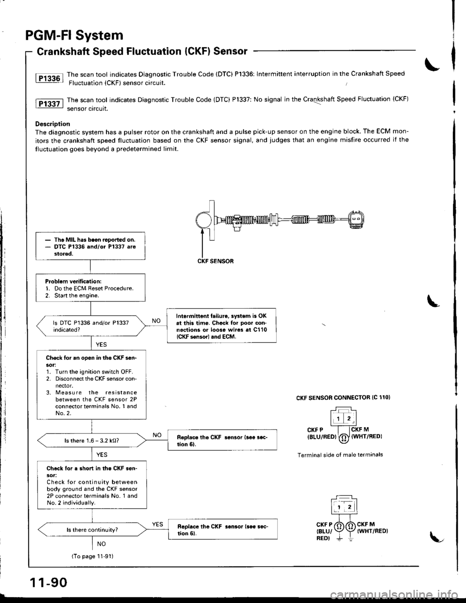
PGM-FI System
Crankshaft Speed Fluctuation {CKF) Sensor
lT13a6l Tje scan tool indicates Diagnostic Trouble Code (DTC) P'1336: lntermittent interruption in the Crankshaft Speed: Fluctuation {CKF) sensor orcurt.
The scan tool indicates Diagnostic Trouble Code (DTC) P1337: No signal in the Craqkshatt Speed Fluctuation (CKF)
sensor circuit.
DescriDtion
The diagnostic system has a pulser rotor on the crankshaft and a pulse pick-up sensor on the engine block. The ECM mon-
itors the crankshaft speed tluctuation based on the CKF sensor signal, and judges that an engine misfire occurred it the
lluctuation goes beyond a predetermined limit.
CKF SENSOR CONNECTOR IC 110)
T:lr+T
IJI',Icrr e -f-fcxr na
{BLU/RED} (D lwHr/REDI
Terminal side of male termanals
- The MIL has beon.ooorted on.- DTC P1336 and/or P1337 arostoaed.
Problem vo.itication:1. Do the ECM Reset Proced!re.2. Start the engine.
lntermittent feilure, swtem is OKat ihis timo. Chcck for ooor oon-noctions or loose wir* ei C110(CKF sonsor) and ECM.
Check for an open in tho CKF sen-sor:1. Turn the ignition switch OFF.2, Disconnect the CKF sensor con-
3. Measu re the resistancebetween the CKF sensor 2Pconnector terminals No. 1 andNo.2.
ls there 1.6 - 3.2 kO?
Check lor . short in tho CKF sen-30t:Check for continuity betweenbody ground and the CKF sensor2P connector terminals No. 1 andNo.2 individually.
ls there continuity?
(To page 11-91)
1 1-90
T:]lf -rl11 2|
TTcKF P /6 6 CKF M
relul Y\Z twxvneotneot ,-- | L
Page 320 of 1681
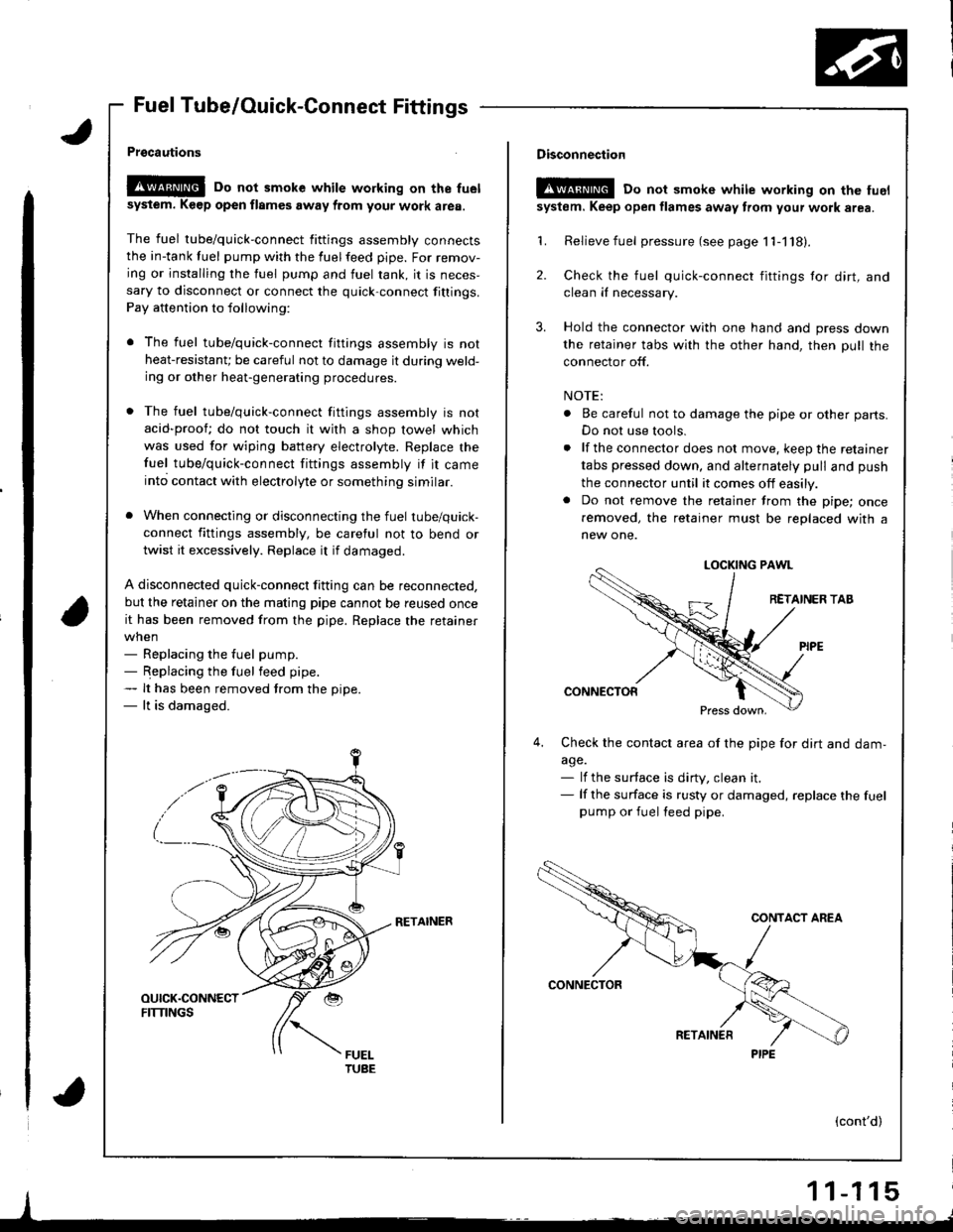
Fuel Tube/Ouick-Connect Fittings
Prgcautions
!@@ Do not smoke while working on the fuel
sysiem. K€ep open flames away from your work area.
The fuel tube/quick-connect fittings assembly connectsthe in-tank tuel pump with the fuelfeed pipe. For remov-
ing or installing the fuel pump and fuel rank, it is neces,sary to disconnect or connect the quick-connect fittings.
Pay attention to following:
r The fuel tube/quick-connect fittings assembly is not
heat-resistanU be careful not to damage it during weld-ing or other heat-generating procedures.
. The fuel tube/quick-connect fittings assembly is not
acid-proof; do not touch it with a shop towel which
was used for wiping battery electrolyte. Replace the
fuel tube/quick-connect fittings assembly if it came
into contact with electrolyte or something similar.
. When connecting or disconnecting the fuel tube/quick-
connect fittings assembly, be careful not to bend or
twist it excessively. Replace it if damaged.
A disconnected quick-connect fitting can be reconnected,
but the retainer on the matlng pipe cannot be reused once
it has been removed from the pipe. Replace the retainer
when- Replacing the fuel pump.- Replacing the fuel feed pipe.- It has been removed trom the oiDe.- lt is damaged.
RETAINER
I
Disconnection
t!!@ Do not smokc white working on the fuel
system. Keep open flames away from your wotk area.
'L Relievefuel pressure (see page 11-118).
2. Check the fuel quick-connect fittings tor dirt, andclean iI necessary.
3. Hold the connector with one hand and press down
the retainer tabs with the other hand, then pull the
connector off.
NOTE:
. Be careful not to damage the pipe or other parts.
Do not use tools.
. lf the connector does not move, keep the retainer
tabs pressed down, and alternately pull and push
the connector until it comes off easily.. Do not remove the retainer from the pipe; once
removed, the retainer must be replaced with a
new one.
LOCKING PAWL
RETAINER TAB
CONNECTOR
Press down,
4,Check the contacl area of the pipe for dirt and dam,
a9e.- lf the surface is dirty, clean it.- lf the surface is rusty or damaged, replace the fuelpump or fuel feed pipe.
(cont'd)
1 1-1 15
PIPE