HONDA INTEGRA 1998 4.G Workshop Manual
INTEGRA 1998 4.G
HONDA
HONDA
https://www.carmanualsonline.info/img/13/6069/w960_6069-0.png
HONDA INTEGRA 1998 4.G Workshop Manual
Trending: c503, warranty, wiring diagram, service, wheel bolts, refrigerant type, power steering
Page 191 of 1681
I
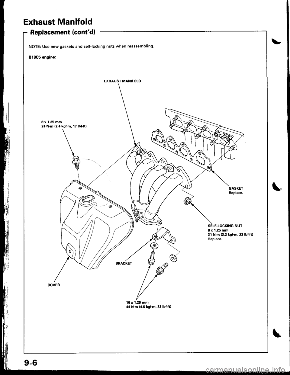
Exhaust Manifold
Replacement (cont'd)
NOTE: Use new gaskets and selt-locking nuts when reassembling-
818C5 ongine:
8 x 1.25 mm2a N.m 12.,r kgf.m, 17 lbf.ftl
GASKETReplace.
8 x 1.25 mm3l N.m 13.2 kgf.m, 23 lbtftlReplace.
10 x 1.25 mma,l N.m (4.5 kg{.m, 33 lbf.ftl
EXHAUST MANIFOLD
\A
9-6
Page 192 of 1681
J
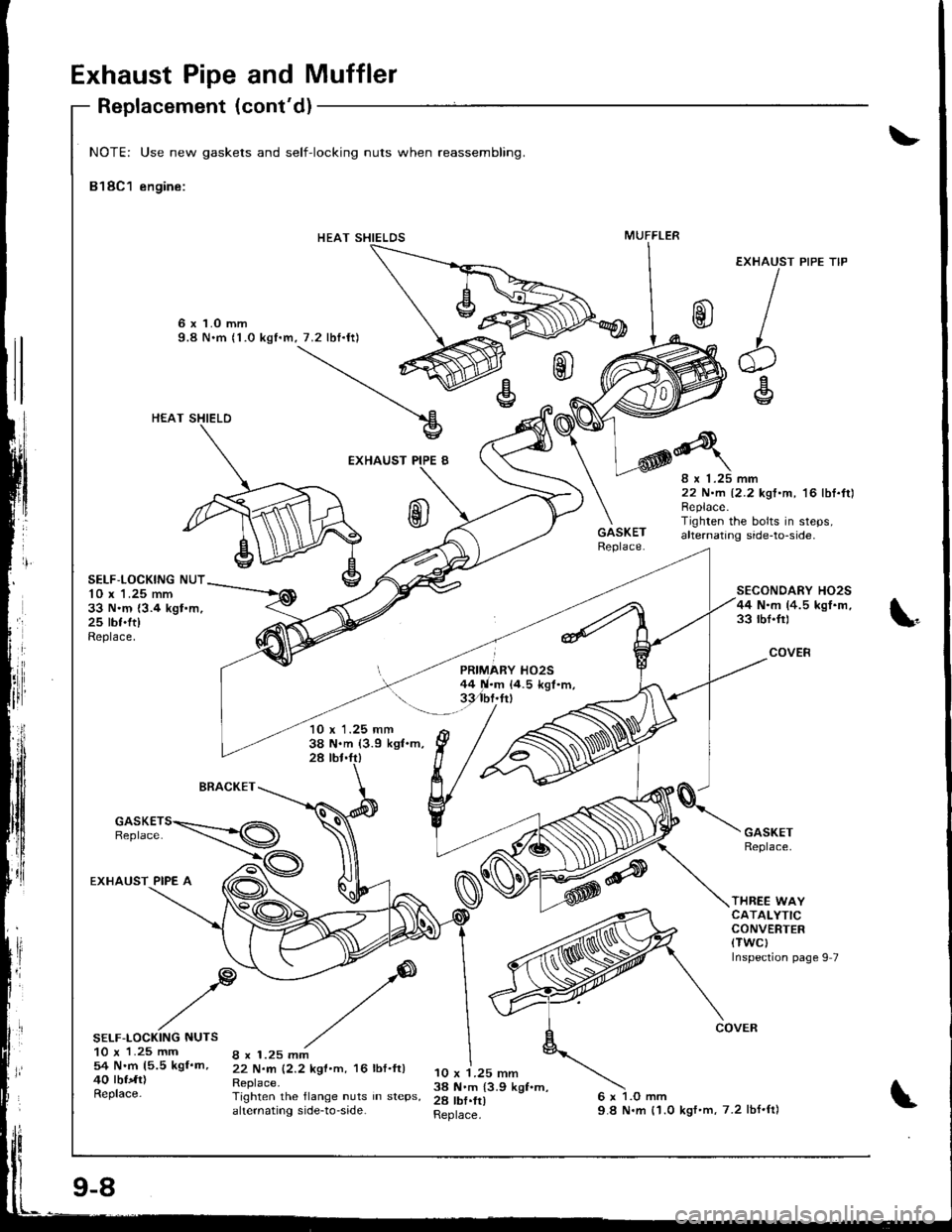
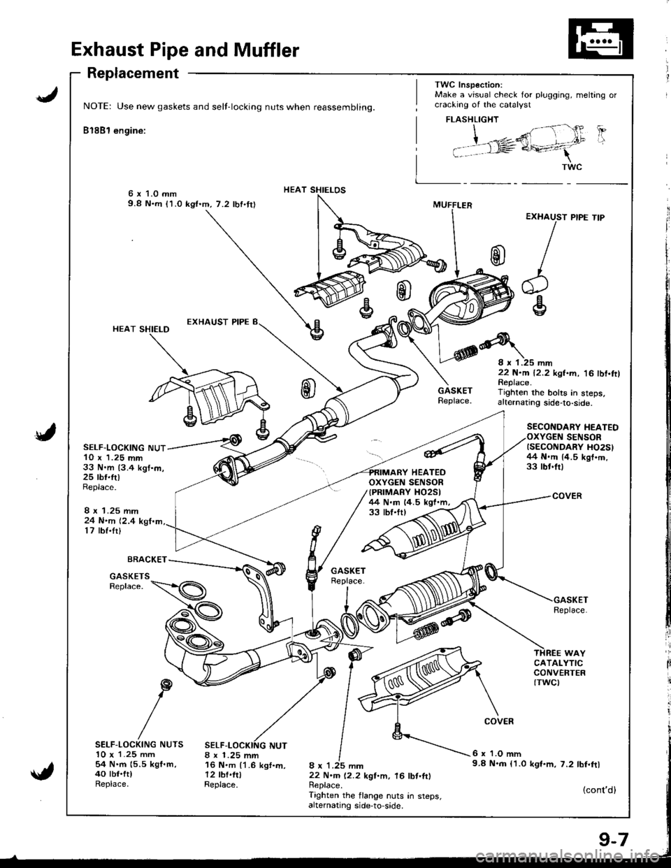
Exhaust Pipe and Muffler
Replacement
NOTE: Use new gaskets and self-locking nuts when reassembling.
Bl8Bl engine:
HEAT SHIELOS6 x 1.0 mm9.8 N.m (1.0 kgf.m,7.2 lbf.tr)
{
HEAT SHIELD
SELF-LOCKING NUT10 x 1.25 mm33 N.m {3.4 kgt.m,25 rbr.ft)Replace.
24 N.n 12.417 rbf.tr)
BRACKET
8 x 1.25 mm16 N.m {1.6 kgf.m,12 tbf.fttReplace.
33 tbt.tr,
8 x 1.25 mm22 N.m 12.2 kgf.m. 16 lbt.ftlReplace.Tighten the flange nuts in steps,alternating side-to,side.
Replace.
6 x 'l.O mm9.8 N.m l'1.0 kgt.m, 7.2 tbf.ftl
{cont'd}
GASKETSReplace.
ir
li
it
SELF-LOCKING NUTS10 x 1.25 mm54 N.m {5.5 kgf.m,40 tbt.ft)Replace.
TWC Insp€ction:Make a visual check for plugging, meltang orcracking of the catalyst
EXHAUST
/
r
cg
HEATEDOXYGEN SENSOR{PRIMARY XO25I/+4 N.m 14.5 kgf.m,
FLASHLIGHT
| ;"1- {' 'PI i ,"*,2ffi - .t"
i t rl= a+-41
I _ _*"
PIPE TIP
8 r 1.25 mm22 N.m 12.2 kgf.m, '16 tbf.ftlReplace.Tighten rhe bolts in steps,altelnating side-to-side.
SECONDARY HEATEDSENSORISECONDARY HO2S}/+4 N.rn 14.5 kgt'm,33 tbr.frl
9-7
Page 193 of 1681
Exhaust Pipe and Muffler
EXHAUST
b
'+l\v
rl
IIrl
NOTE: Use new gaskets and self-locking nuts when reassembling.
818C1 engine:
6 x 1.O mm9.8 N.m (1.0 kgf.m, 7.2 lbf.ft)
HEAT SHIELD
EXHAUST PIPE 8
Replacement (cont'd)
SELF,LOCKING NUT10 x 'l .25 mm33 N.m {3.4 kgt.m,25 tbf.ft)Replace.
PIPE TIP
BRACKET
10 x 1.25 mm38 N.m (3.9 kgl.m,28 tbt.fr)
8 x 1.25 mm22 N.m 12.2 kgt.m, '16 lbI.ft)Replace.Tighren the bolts in steps,alternating side-to-side.
SECONDARY HO2S44 N.m (4.5 kgI.m,33 rbf.fr)
COVER
THREE WAYCATALYTICCONVERTER(TWCI
Inspection page 9 7
EXHAUST PIPE A
SELF-LOCKING NUTS10 x 1.25 mm54 N.m 15.5 kgf.m,40 tbfdr)Replace-
8 x 1.25 mm22 N.rn 12.2 kgf.m, 16 lbf.ft)Replace.Tighten the flange nuts in steps,ahernating side-to-side.
10 x 1.25 mm3a N.m {3.9 kgf.m,28 tbf.fr)Replace.
HEAT SHIELDSMUFFLER
9-8
9.8 N.m {'1.0 kgf'm,7.2 lbf'ft)
Page 194 of 1681
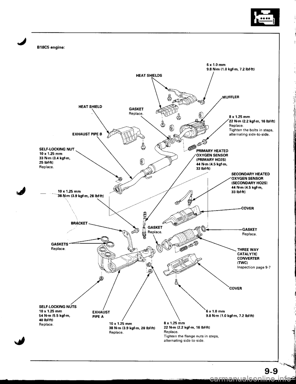
818C5 engine:
6x1.0mm9.8 N.m {1.0 kgf.m.7.2lbtft)
EXHAUST PIPE B
8 x 1.25 mm22 N.rn {2.2 kgt.m, 16 lbtftlReplace.Tighten the bolts in steps,alternating side to'side.
SELF.LOCKING NUT10 x 1.25 mrn33 N.m {3.4 kgl.m,2s rbf.ftJReplace.
PRIMARY HEATEDSENSOFIPRIMARY H02S)4,1 N.m (4.5 kgt.m.33 tbf.ftt
SECONDARY HEATEOSENSOR
J
{SECONDARY H02S)4,0 N.m (4.5 kgf.m,33 tbf.ft)10 x 1.25 mm3&t!.m t3.9 kgt.n.28 lbf.ftl. \
ElacKEr -*_____GASKETReplace-
GASKETSReplace.
Replace.
THREE WAYCATALYTICCONVERTERtTwc)Inspection page 9 7
SELF.LOCKING10 x 1.25 mm5a N.m {5.5 kgt m.40 tbf.ftlReplace.
6x1.0mm9.8 N.m (1.0 kgf.m, ?.2 lbt.ftl
10 x 1.25 mm38 N.m 13.9 kgt m,28 lbt.ftlReplace.
8 x 1.25 mm22 N.m 12.2 kgtm, 16lbf.h)Replace.Tighten the flange nuts in steps,alternating side to side.
_@
\
Page 195 of 1681
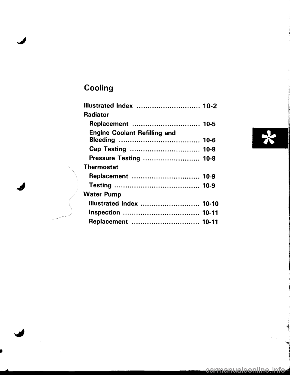
Cooling
lllustrated Index ........
Radiator
Replacement ..............
Engine Coolant Refilling and
Bleeding
Cap Testing
Pressure Testing
Thermostat
Replacement ..............
Testing
Water Pump
lllustrated Index .........
Inspection
Replacement ...............
10-2
10-5
10-6
10-8
10-8
10-9
10-9
10-10
10-11
10-11
Page 196 of 1681
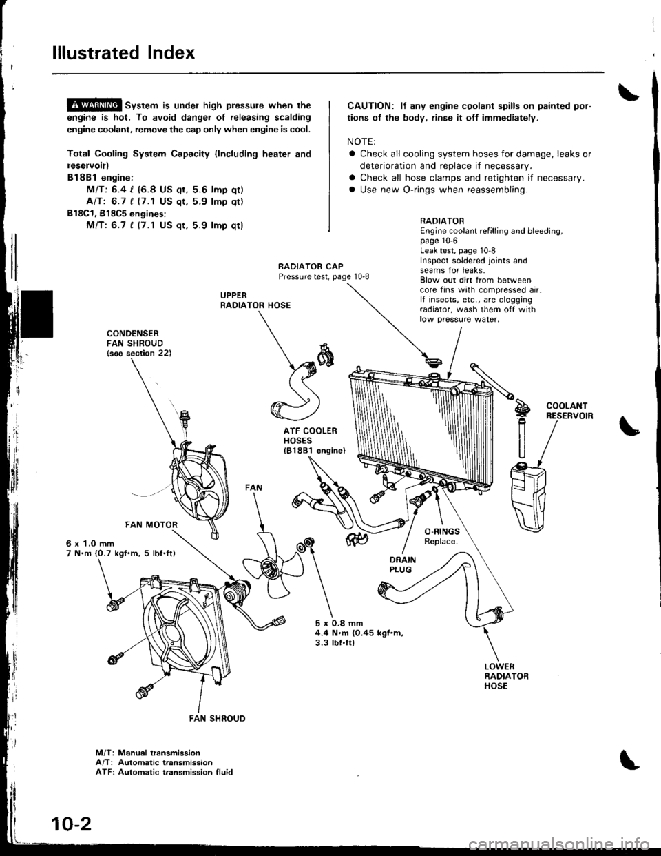
lllustrated Index
!$!!@ sv"t"m is under high plessure when the
engine is hot, To avoid dangei of releasing scalding
engine coolant, remove the cap only when engine is cool.
Total Cooling System Capacity {lncluding heater and
leservoir)
Bl8Bl engine:
MIT: 6.4 l. {6.8 US qt, 5.6 lmp qt)
Ant 6.7 t (7.1 US qt,5.9 lmp qt)
B18C1, 818C5 engines:
Mfi:6.7 t (7.1 US qt, 5.9 lmp qt)
CAUTION: lf any engine cgolant spills on painted por-
tions of the body, rinse it off immediately.
NOTE:
a Check all cooling system hoses for damage, leaks or
deterioration and replace il necessary.
a Check all hose clamps and retighten if necessary.
a Use new O-rings when reassembling.
RADIATOREngine coolant refilling and bleeding,page 10-6Leak test, page 10 8Inspecl soldered joints andseams for leaks,RAOIATOR CAPPressure test, page 10-8
UPPERRADIA
rl
]
CONDENSERFAN SHROUD{s€o section 22)
6 x 1.0 mm7 N.m {0.7 kgl.m, 5 lbf'ftl
5x0.8mm4.4 N.m (0.45 kgl.m,3.3 tbt.ft)
Blow out dirt from betweencore fins with compressed air.lf insects, etc., are cloggingradiator, wash them o{f withlow paessure water,
TOR HOSE
\*
\sffi((
@)
ATF COOLERHOSES181881 €ngin
S!g
R
U
COOLANTRESERVOIR
M/T: Manual lransmissionA/T: Automatic transmissionATF: Automatic t.ansmission fluid
FAN SHROUD
10-2
Page 197 of 1681
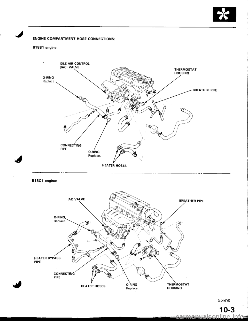
ENGINE COMPARTMENT HOSE CONNECTIONS:
B18B1 engine:
IDLE AIR CONTROL(IAC) VALVE
O-RINGReplace.
BREATHER PIPE
---___...----rs
W
l/TER HOSES
Bl8Cl engine:
HEATER BYPASSPIPE
THER PIPE
AT
(cont'd)
)
HEATER HOSES
10-3
Page 198 of 1681
lllustrated Index
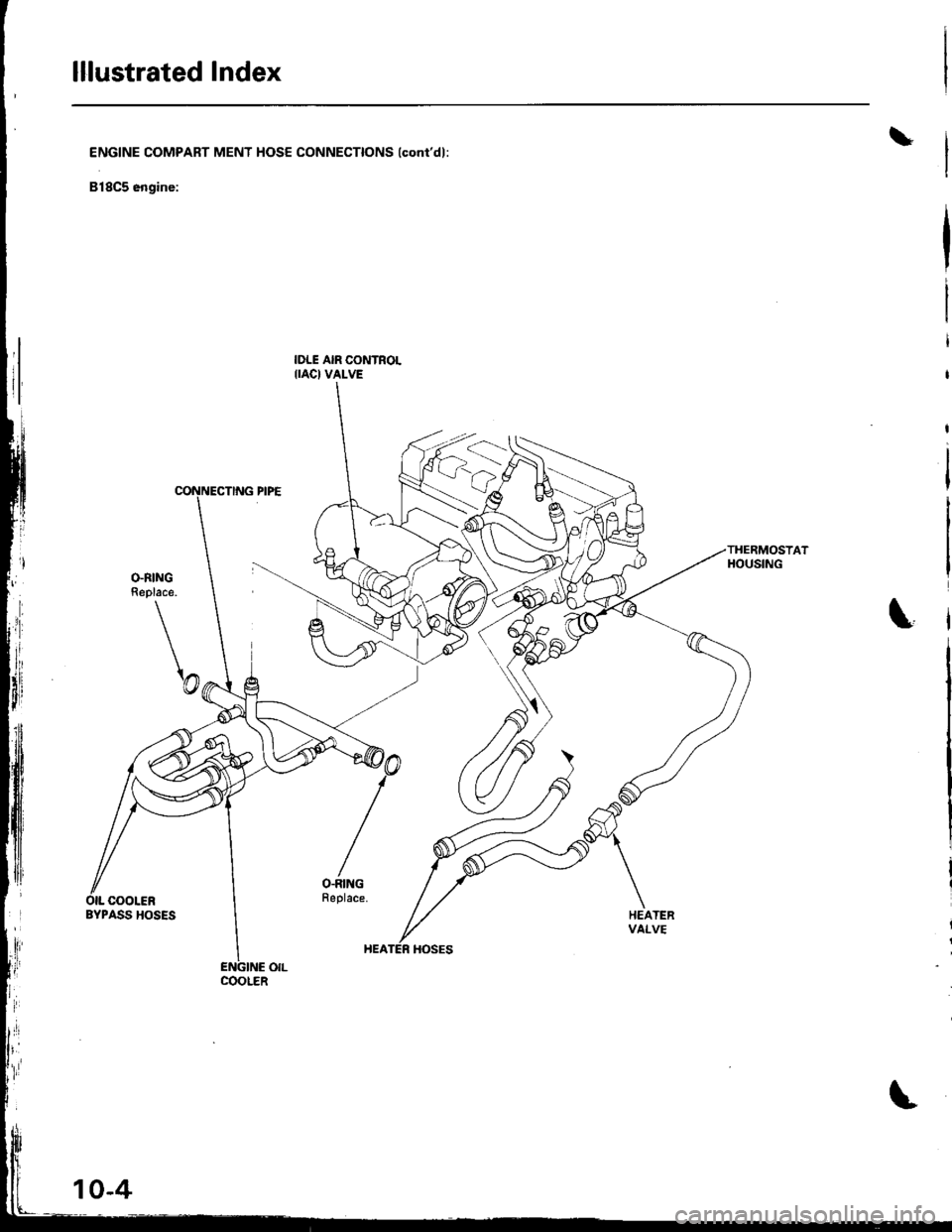
\ENGINE COMPART MENT HOSE CONNECTIONS lconi'dl:
818C5 engine:
IDLE AIR CONTROLIIAC} VALVE
THERMOSTATHOUSING
\
\
O.RINGReplace.
\@
/
O-RINGFeplace.OIL COOLERBYPASS HOSESHEATERvAt_vE
COOLER
Page 199 of 1681
Radiator
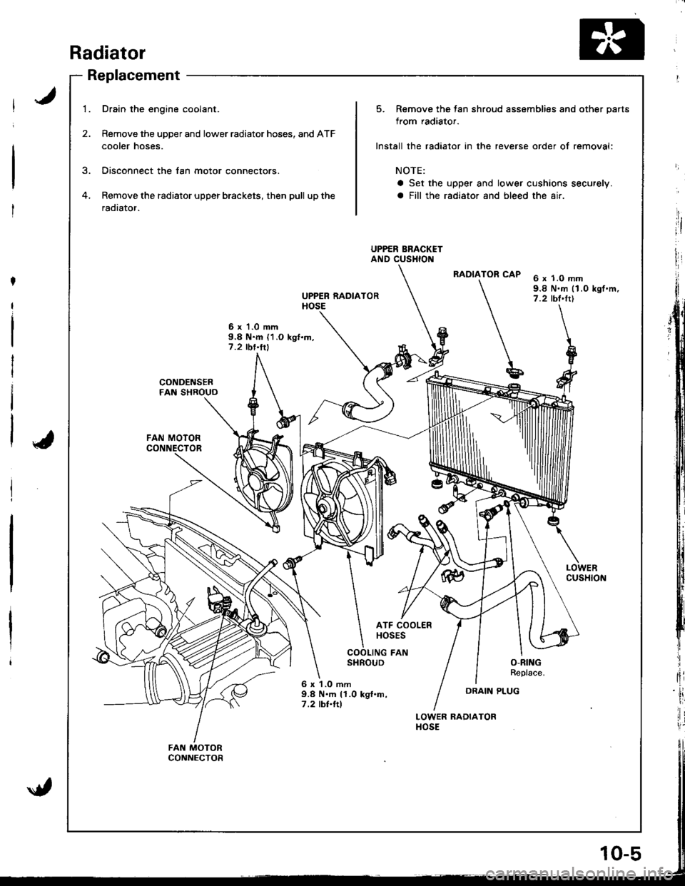
Replacement
1.
2.
Drain the engine coolant.
Remove the upper and lower radiator hoses, and ATF
cooler hoses.
Disconnect the lan motor connectors.
Remove the radiator upper brackets, then pull up the
radiator.
6 x 'l .0 mm9,8 N.m {1.O kgf.m,7.2 tbl'ltl
UPPER RADIATORHOSE
6 x 1.0 mm9.8 N.m (1.0 kgf.m,7.2 tbt'trl
LOWERCUSHION
CONDENSERFAN SHROUO
FAN MOTOR
ATF COOLERHOSES
COOLING FANSHROUDO-RINGReplace.
6 x 1.O mm9.8 N.m 11.0 kgf.m,7 .2 tbl.ftl
LOWER RADIATORHOSE
FAN MOTORCONNECTOR
5. Remove the tan shroud assemblies and other parts
from radiator.
Install the radiator in the reverse order of removal:
NOTE:
a Set the upper and lower cushions securely.
a Fill the radiator and bleed the air.
UPPER BRACKETAND CUSHION
RADIATOR CAP
u
DRAIN PLUG
jit
I
HI
I
fli
ii
lir
Page 200 of 1681
Radiator
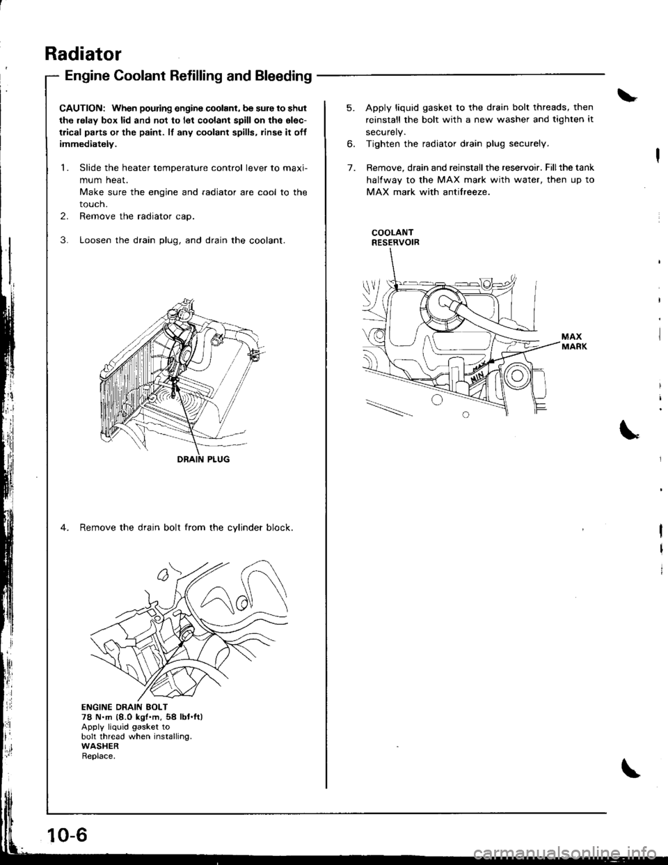
Engine Coolant Refilling and Bleeding
CAUTION: When pouring engine coolant, be sure to shut
th6 relay box lid and not to l€t coolant spill on th6 el€c-
trical parts or the paint. lf any coolant spills, rinse it off
immediately.
1. Slide the heater temDerature control lever to maxi-
mum heat.
Make sure the engine and radiator are cool to the
touch.
2. Remove the radiator cap.
3. Loosen the drain plug, and drain the coolant.
4. Remove the drain bolt from the cvlinder block.
ji
Ii'
l:ll
ENGINE DRAIN EOLT78 N.m {8.0 kgt'm,54 lbt.ft)Apply liquid gasket tobolt thread when installing.WASHERReplace.
10-6
5. Apply liquid gasket to the drain bolt threads, then
reinstall the bolt with a new washer and tighten it
securely.
6. Tighten the radiator drain plug securely.
7. Remove, drain and reinstall the reservoir. Fillthe tank
halfway to the MAX mark with water, then up to
MAX mark with antifreeze.
COOLANTRESERVOIR
I
I
I
Trending: timing belt, fuses, transmission oil, parking sensors, sensor, mirror, fuse
