HONDA INTEGRA 1998 4.G Workshop Manual
Manufacturer: HONDA, Model Year: 1998, Model line: INTEGRA, Model: HONDA INTEGRA 1998 4.GPages: 1681, PDF Size: 54.22 MB
Page 151 of 1681
Page 152 of 1681
/
li
l
Main Bearings
Clearance
2.
3.
1.
4.
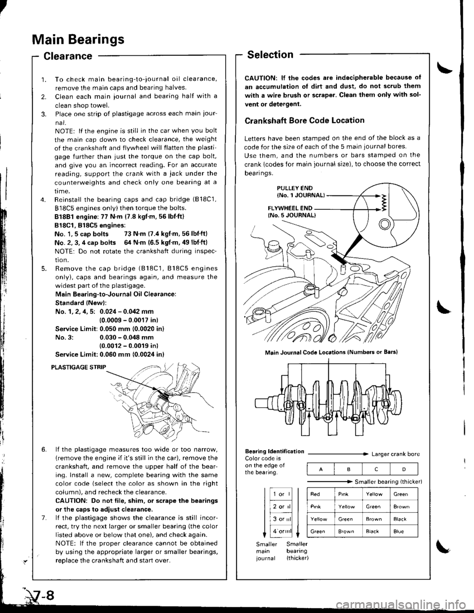
To check main bearing-to-iournal oil clearance,
remove the main caps and bearing halves.
Clean each main iournal and bearing half with a
clean shop towel.
Place one strip of plastigage across each main iour-
na l-
NOTE: lf the engine is still in the car when you bolt
the main cap down to check clearance, the weight
of the crankshaft and flywheel will flatten the plasti'
gage further than just the torque on the cap bolt,
and give you an incorrect reading. For an accurate
reading, support the crank with a jack under the
counterweights and check only one bearing at a
trme.
Reinstall the bearing caps and cap bridge (B18C1,
B18C5 engines only)then torque the bolts.
Bl8Bl engine: 77 N'm (7.8 kgt.m.56lbf.ft)
B18Cl,818C5 engines:
No. 1,5 cap bolts 73 N.m (7.4 kgf.m,56lbnftl
No. 2. 3, 4 cap bolts 64 N.m {6.5 kgf m. 49 lbf ftl
NOTE: Do not rotate the crankshaft during inspec-
tro n.
Remove the cap bridge (818C1, 818C5 engines
only), caps and bearings again, and measure the
widest part of the plastigage.
Main Bearing-to-Journal Oil Clearance:
Standard lNew):
No. 1, 2, 4, 5: 0.024 - 0.042 mm
10.0009 -0.0017 in)
Service Limit:0.050 mm (0.0020 in)
No.3:0.030 - 0.048 mm
10.0012 - 0.0019 inl
Service Limit:0.060 mm {0.0024 inl
PLASTIGAGE STRIP
lf the plastigage measures too wide or too narrow,
{remove the engine if it's still in the car), remove the
crankshaft, and remove the upper half of the bear-
ing. lnstall a new, complete bearing with the same
color code (select the color as shown in the right
column), and recheck the clearance.
CAUTION: Do not file, shim. or scrape the bearings
or the caps to adiust clearance.
lf the plastigage shows the clearance is still incor-
rect, try the next larger or smaller bearing (the color
listed above or below that one), and check again.
NOTE: lf the oroDer clearance cannot be obtained
by using the appropriate larger or smaller bearings.
reolace the crankshaft and start over.
Selection
CAUTION: lf the codes ale indecipherable because of
an accumulation oI dirt and dust, do not scrub them
with a wire bru6h or scraper. Clean lhem only with sol-
vent or detergent.
Crankshaft Bore Code Location
Letters have been stamped on the end of the block as a
code for the size of each of the 5 main iournal bores
Use them, and the numbers or bars stamped on the
crank {codes for main journal size), to choose the correct
Dean nqs,
FLYWHEEL END
Main JouhalCode Locations (Numbe.s or Bars)
Bearing ldentif ic.tionColor code ison the edge ofthe bearing.
Larger crank bore
acD
"""""""" Smallerbearingithicker)
Green
Elack
B'ownBlackElue
Smaller Smallermain bearingjournal lthacker)
Page 153 of 1681
I
IConnecting Rod Bearings
Clearance
1. Remove the connecting rod cap and bearing half.2. Clean the crankshaft rod journal and bearing halfwith a clean shop towel.
3. Place the plastigage across the rod journal.
4. Reinstall the bearing half and cap, and torque thenuts (818C5 engine: see page 7-19).
81881 engine:31 N.m (3.2 kgnm,23 tbf.ftl
Bl8Cl engine:44 N.m (4.5 kgl.m.33 tbl.ft)
NOTE: Do not rotate the crankshaft during inspection.
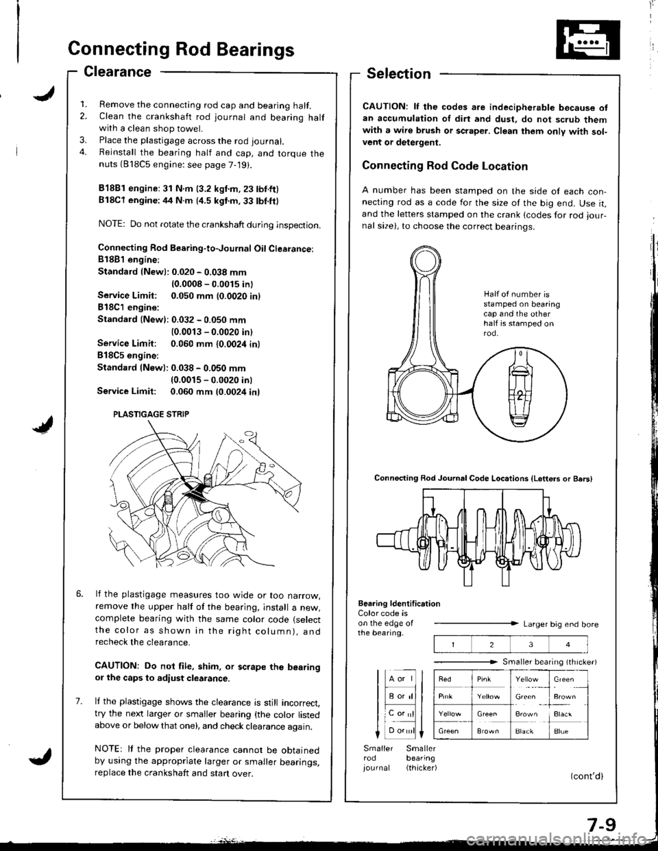
Connecting Rod Bearing-to-Journal Oil Clearance:81881 engine:
Standard {Newl: 0.020 - 0.038 mm
{0.0008 - 0.0015 inl
Service Limit: 0.050 mm {0.0020 inl
818C1 engine:
Standald {Newl: 0.032 - 0.050 mm
10.0013 - 0.0020 in)
Service Limit: 0.060 mm {0.0024 in}
B18C5 engine:
Standard lNew): 0.038 - 0.050 mm(0.0015 - 0.0020 inl
Service Limit: 0.060 mm t0.0024 inl
lf the plastigage measures too wjde or too narrow,remove the upper half of the bearjng, install a new,complete bearing with the same color code (select
the color as shown in the rig ht column), andrecheck the clearance.
CAUTION: Do not file, shim, or scrape the bearingor the caps to adiust clearance.
It the plastigage shows the clearance is still incorrect,try the next larger or smaller bearing (the color listedabove or below that one), and check clearance again.
NOTEr It the proper clearance cannot be obtainedby using the appropriate larger or smaller bearings,replace the crankshaft and stan over.
Selection
CAUTION: lf the codes are indecipherable because ofan accumulation of dirt and dust, do not scrub themwith a wire brush or scraper. Clean them only with sol-vent or delergent.
Connecting Rod Code Location
A number has been stamped on the side of each con-necting rod as a code for the size of the big end. Use it,and the letters stamped on the crank lcodes for rod iour-nal size), to choose the correct bearinqs.
Connecting Rod Journal Code Loc.tions {Letters or Bers)
Beering ldentification
23
Y"rl.:_,
Gie& ,
!**
i:1"
BlackBlue
Color code ison the edge oIthe bearing.Larger big end bore
Smaller bearing (th rche.)
lHll
I F;;lll
lL".;|l
Smaller Smallerrod bearing
iournal (thicker)
Half ot number isstamped on bearingcap and the otherhalf is stamped onrod.
PLASTIGAGE STRIP
Page 154 of 1681
Connecting Rod BearingsCrankshaft
Selection (cont'dlRemoval
818C5 engine:
CAUTION: lf the codes are indecipherable because of
an accumulation of dirt and dust, do not scrub them
with a wire brush or scraper. Clean them only with sol-
vent or detergent.
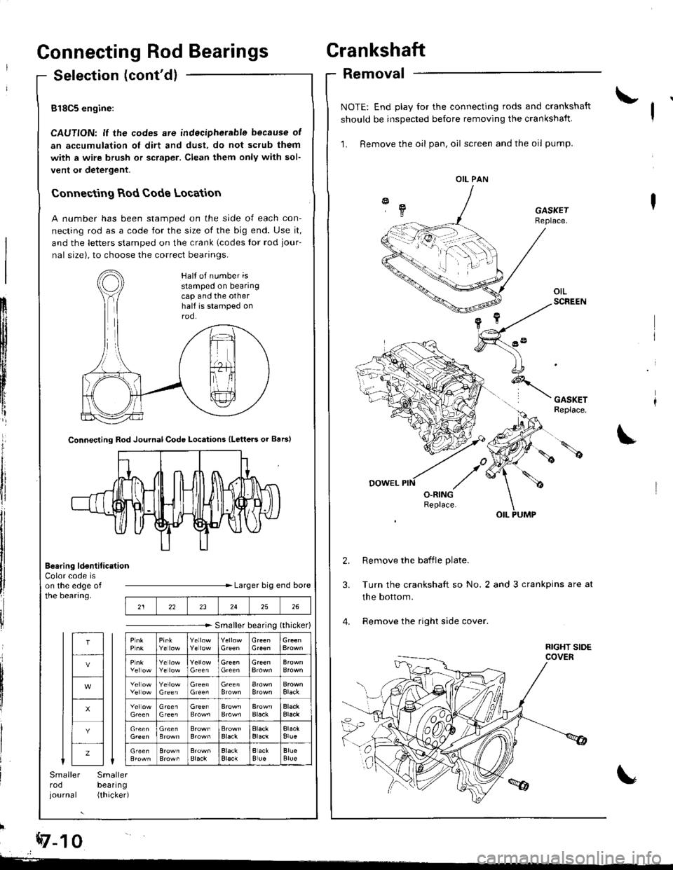
Connecting Rod Code Location
A number has been stamped on the side of each con-
necting rod as a code for the size of the big end. Use it,
and the letters stamped on the crank lcodes for rod jour-
nal size), to choose the correct bearings.
ilb
Color code ison the edge ofthe bearing.Larger big end bore
Smaller bearing (thicker)
Smallerbeal|ng(thicked
1rI
llli
tl
ilI
I
*z-t o
Smallerrodjournal
Connecting Rod Journal Code Locations {Letters or Barsl
Beering ldentitication
NOTE: End play for the connecting rods and crankshaft
should be inspected before removing the crankshaft.
1. Remove the oil pan, oil screen and the oil pump.
GASKETReplace.
Remove the baffle plate.
Turn the crankshaft so No.2 and 3 crankpins are at
the bottom.
Remove the right side cover.
OIL PAN
Half of number isstamped on bearingcap and the otherhalf is stamped onrod.
212223242526
T
z
Black
Black
Blue
Page 155 of 1681
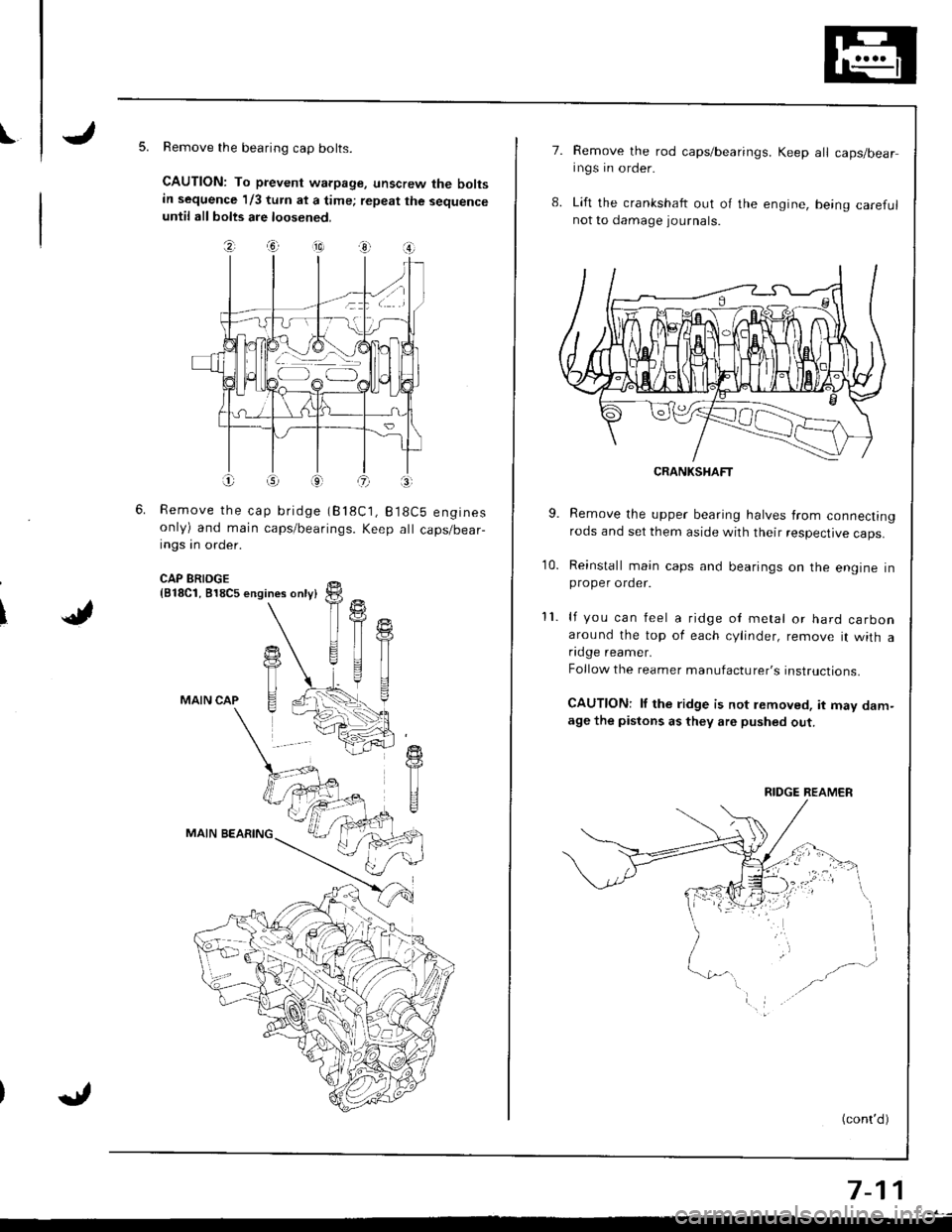
IRemove the bearing cap bolts.
CAUTION: To prevent warpage, unscrew the boltsin sequence 1/3 turn at a time; repeat the sequenceuntil all bolts are loosened.
\J
?, .ia --10) 3r O
Remove the cap bridge (818C1, B18Cb enginesonly) and main caps/bearings. Keep all caps/bear-ings in order.
CAP BRIDGE{818C1, 818C5 engines only}
MAIN CAP
MAIN BEARING
11
T
T
TI
7.Remove the rod caps/bearings. Keep all caps/bearings in order.
Lift the crankshaft out o{ the engine, being care{ulnot to damage journals.
CRANKSHAFT
9. Remove the upper bearing halves from connectingrods and set them aside with their respective caps.
10. Reinstall main caps and bearings on the engine inproper order.
11. lf you can feel a ridge oI metal or hard carbonaround the top of each cylinder, remove it with afldge reamer.
Follow the reamer manufacturer's instructions.
CAUTIONT lf the ridge is not lemoved, it may dam-age the pistons as they are pushed out.
(cont'd)
7-11
RIDGE REAMER
Page 156 of 1681
Grankshaft
Removal (cont'dl
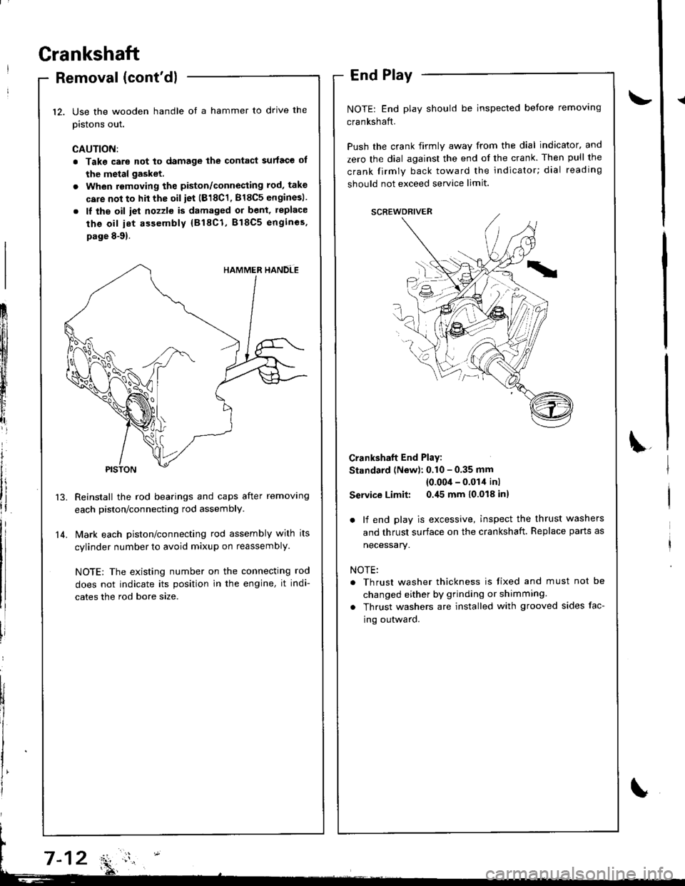
Use the wooden handle ot a hammer to drive the
pistons out.
CAUTION:
. Take care not to damage the contact surface ot
the metal gasket.
. When removing the piston/connecting rod, take
care not to hit the oil iet (818C1, 818C5 enginesl.
. ll the oil iet nozzle is damaged or bent, replace
the oil iet assembly {818C1, B18C5 engincs.
page 8-9).
Reinstall the rod bearings and caps after removing
each piston/connecting rod assembly.
l\4ark each piston/connecting rod assembly with its
cylinder number to avoid mixup on reassembly.
NOTE; The existing number on the connecting rod
does not indicate its position in the engine, it indi-
cates the rod bore size.
End Play
NOTE: End play should be inspected before removing
crankshaft.
Push the crank firmly away from the dial indicator, and
zero the dial against the end of the crank. Then pull the
crank firmly back toward the indicator; dial reading
should not exceed service limit.
Crankshaft End Play:
Standard (New): 0.10 - 0.35 mm
{0.00'l - 0.014 inl
Service Limit: 0.45 mm 10.018 inl
. lf end play is excessive, inspect the thrust washers
and thrust surface on the crankshaft. Replace parts as
necessary.
NOTE:
. Thrust washer thickness is tixed and must not be
changed either by grinding or shimming.
. Thrust washers are installed with grooved sides fac-
ing outward.
12.
14.
Frlfll
ftl
t
iffi[l
t,,tlr
lt
i
Page 157 of 1681
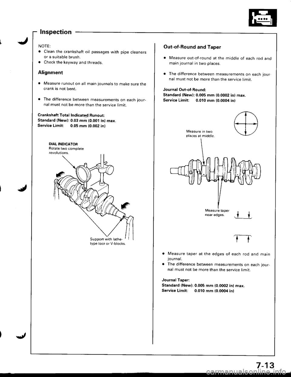
NOTE:
. Clean the crankshaft oil passages with pipe cleanersor a suitable brush.
. Check the keyway and threads.
Alignment
. Measure runout on all main journals to make sure thecrank as not bent.
. The difference between measurements on each ,our-nal must not be more than the service limit.
Crankshaft Total Indicated Runout:
Standard (New): 0.03 mm (0.001 inl max.Service Limit: 0.05 mm 10.002 in)
DIAL INDICATORRotate two complete
Suppon with lathe-type toolor V-blocks.
Out-of-Round and Taper
. Measure out-of-round at the middle of each rod andmain journal in two places.
. The difference between measurements on each jour
nal must not be more than the service limit.
Journal Out-oI-Round:
Standard {Newl:0,005 mm (0.0002 inl max.
Service Limit: 0,010 mm {0.0004 inl
places at middle.
Measure tapernear edges..r +
. Measure taper at the edges of each rod
JOUrnal.. The difference between measurements on
nal must not be more than the service limit.
Journal Taper:
Standard {New): 0.005 mm (0.0002 in) max.
Service Limit: 0.010 mm 10.0004 inr
and matn
each Jour-
7-13
Page 158 of 1681
Cylinder Block
Inspection
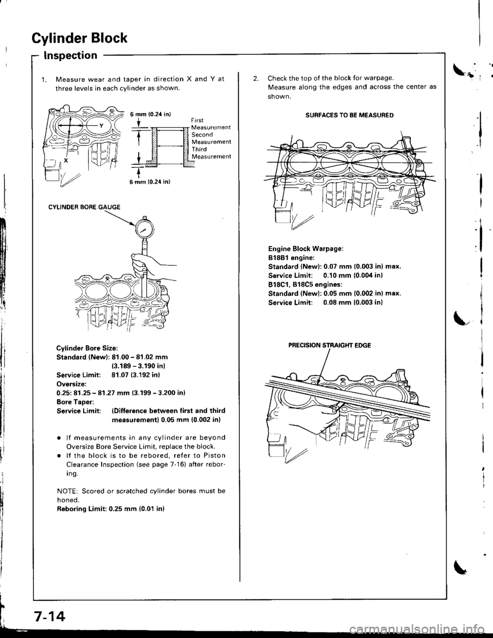
1. Measure wear and taper in direction
three levels in each cylinder as shown.
XandYat
{0.24 in}6mm
tFirst
Second
ThirdMeasurement
6 mm 10.24 in)
CYLINDER BORE GAUGE
Cylinder Bore Size:
Standard (N€w): 81.00 - 81.02 mm
(3.189 - 3.190 inl
Service Limit: 81.07 (3.192 inl
Oversize:
0.251 81.25 - 41.27 mm 13.199-3.200 inl
Bore Taoer:
S€rvice Limit: lDifference betwcen first and third
measu;ement) 0.05 mm (0.002 inl
. lf measurements in any cylinder are beyond
Oversize Bore Service Limit, replace the block.
. lf the block is to be rebored, reler to Piston
Clearance Inspection (see page 7-16) after rebor-
I ng.
NOTE: Scored or scratched cylinder bores must be
noneo,
Reboring Limit: 0.25 mm (0.01 inl
ll
:i
I
I
Check the top oI the block for warpage.
Measure along the edges and across the center as
sh own.
SURFACES TO 8E MEASURED
Engine Block Warpage:
B188l engine:
Standard {New}: 0.07 mm (0,003 inl max.
Service Limit: 0.10 mm {0.004 in)
818C1, 818C5 engines:
Standard (Newl:0.05 mm 10.002 inl max.
Service Limit: 0.08 mm (0.003 in)
I
I
rl
LC
'/rz
PRECISION STRAIGHT EDGE
Page 159 of 1681
11
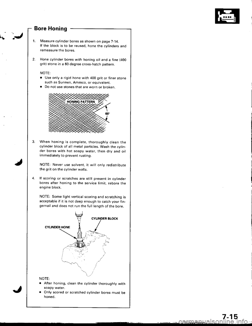
Bore Honing
l/easure cylinder bores as shown on page 7-14.lf the block is to be reused, hone the cylinders andremeasure the bores.
Hone cylinder bores with honing oil and a fine (400
grat) stone in a 60 degree cross-hatch pattern.
NOTE:
. Use only a rigid hone with 400 grit or finer stonesuch as Sunnen, Ammco, or equivalent.a Do not use stones that are worn or oroKen.
When honing is complete, thoroughly clean thecylinder block of all melal particles. Wash the cylin-der bores with hot soapy water, then dry and oilimmediately to prevent rusting.
NOTE: Never use solvent, it wili only redistribute
the grit on the cylinder walls.
lf scoring or scratches are still present in cylinderbores after honing to the service limit, rebore theengine block.
NOTE: Some light vertical scoring and scratching isacceptable if it is not deep enough to catch your fin-gernail and does not run the full length ofthe bore.
NOTE:
. After honing, clean the cylinder thoroughly withsoapy water.o Only scored or scratched cylinder bores must behoned.
4.
7-15
Page 160 of 1681
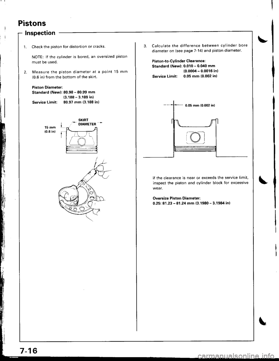
Pistons
Inspection
1. Check the piston lor distortion or cracks.
NOTE: lf the cylinder is bored, an oversized piston
musl be used.
2. Measure the piston diameter at a point 15 mm
(0.6 in) from the bottom of the skrrt.
Piston Diameter:
Standard (Newl: 80.98 - 80.99 mm
(3.188 - 3.189 in)
Service Limit: 80.97 mm (3.188 in)
15 mm{0.6 in)
3. Calculate the difference between cylinder bore
diameter on (see page 7-14) and piston diameter.
Piston-to-Cylinder Clearance:
Standard (Newl: 0.010 - 0.040 mm
(0.0004-00016in)
Service Limit: 0.05 mm (0.002 inl
lf the clearance is near or exceeds the service limit,
inspect the piston and cylinder block for excessive
wear.
Ove6ize Piston Diameter:
0-25181-23 - 81.24 mm 13.1980 - 3.1984 in)
@