engine HONDA INTEGRA 1998 4.G Workshop Manual
[x] Cancel search | Manufacturer: HONDA, Model Year: 1998, Model line: INTEGRA, Model: HONDA INTEGRA 1998 4.GPages: 1681, PDF Size: 54.22 MB
Page 523 of 1681
Transmission
Removal (cont'd)
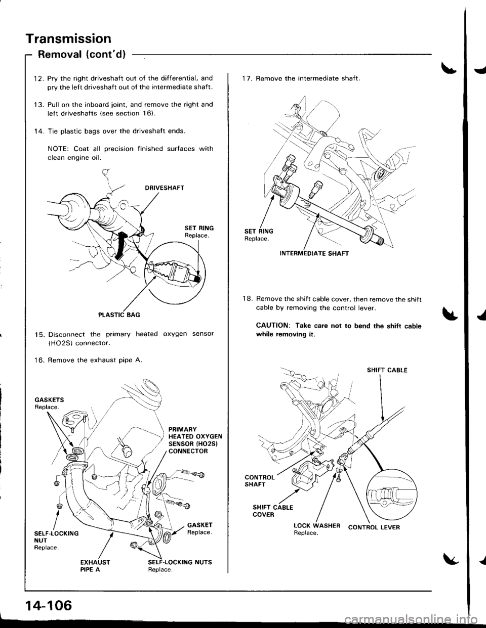
'12. Pry the right driveshaft out of the differential, and
pry the lelt driveshaft out ol the intermediate shaft.
13. Pull on the inboard joint, and remove the right and
lelt driveshatts (see section l6).
14. Tie plastic bags over the driveshalt ends.
NOTE: Coat all precision finished surlaces with
clean engine oil.
Disconnect the primary heated oxygen sensor
(HO2S) connector.
Remove the exhaust pipe A.
| 5.
to.
PRIMARYHEATEO OXYGENSENSOR {HO25lCONNECTOR
SELF-LOCKINGNUTReplace.
14-106
J
J
.l
18.
'17. Remove the intermediate shaft.
Remove the shitt cable cover, then remove the shilt
cable by removing the control lever.
CAUTION: Take care not to bend the shifr cablewhile removing it.
CONTROL LEVER
INTERMEDIATE SHAFT
SHIFT CABLE
Page 524 of 1681
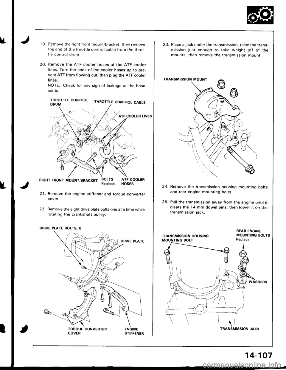
u19.Remove the right front mount/bracket, then remove
the end of the throltle control cable from the throt-
tle control drum.
Remove the ATF cooler hoses at the ATF cooler
lines. Turn the ends of the cooler hoses up to pre-
vent ATF from flowing out, then plug the ATF cooler
lines.
NOTE: Check for any sign ol leakage at the hosejornrs.
THROTTLE CONTROL CABLE
20.
f
RIGHT FRONT MOUNT/BRACKET
21. Remove the engine stiftener and torque converter
cover,
22. Remove the eight drive plate bolts one at a time whilerotating the crankshaft pulley.
EOLTS ATF COOLERReplace. HOSES
ENGINESTIFFENERCOVERTRA
14-107
23. Place a jack under the transmission. raise the trans-mission just enough to take weight off of the
mounts, then remove the transmtssion mount.
TRANSMISSION MOUNT
24. Remove the transmission housing mounting bolts
and rear engine mounting bolts.
25. Pull the transmission away trom the engine until itclears the 14 mm dowel pins, then lower it on thetransmission jack.
REAR ENGINEMOUNTING BOLTSReplace.
WASHERS
MISSION JACK\NS
Page 584 of 1681
Transmission
lnstallation
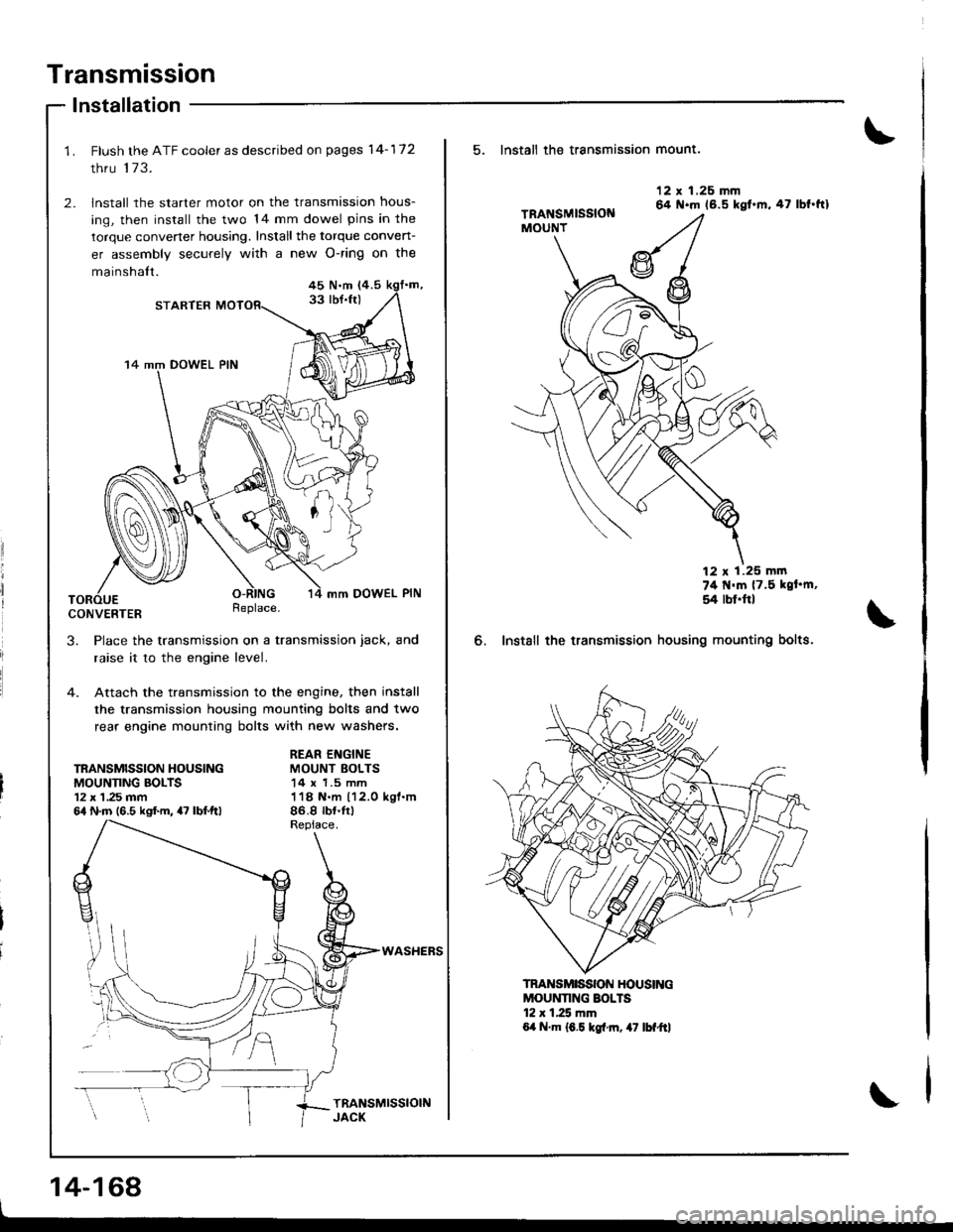
Flush the ATF cooler as described on pages 14-172
thru 173.
lnstall the starter motor on the transmission hous-
ing, then install the two 14 mm dowel pins in the
torque convener housing. Install the torque conven-
er assembly securely with a new O-ring on the
mainshalt.45 N.m (4.5
33 lbJ.ft)STARTER
14 mm DOWEL PIN
mm DOWEL PIN
CONVERTERReplace.
3. Place the transmission on a transmission jack, and
raise it to the engine level.
4. Attach the transmission to the engine, then install
the transmission housing mounting bolts and two
rear engine mounting bolts with new washers.
TRANSMISSION HOUSINGMOUNNNG BOLTS12 x 1 ,25 mm64 N.m (6.5 kgf.m, 47 lbf.ftl
REAR ENGINEMOUNT BOLTS14 x 1.5 mm118 N.m 112.0 kgl.m86.8 rb{.tr)
WASHEFS
14-168
5. Install th€ transmission mount.
6. Instsll the transmission
12 x 1.26 mm64 N.m 16.5 kgt.m,47 lbf.ftl
74 t{'m {7.5 kgt'm,
54 rbl.ftl
housing mounting bolts.
MOUNNNG SOLTS12 r 1.25 mm6,t N.m 16.5 kgl.rn, 47 lbf"ftl
TRANSMISSON HOUSING
Page 585 of 1681
7.
10 x 1.25 mm1+4 N.m (4.5 kgt.m,33 tbf.ft)
TOROUECONVERTERCOVER
EI{GINESTIFFEI{ER
I x 1.25 mm24 N.m 12.4 kgf.m,17 rbf.ftl
8.
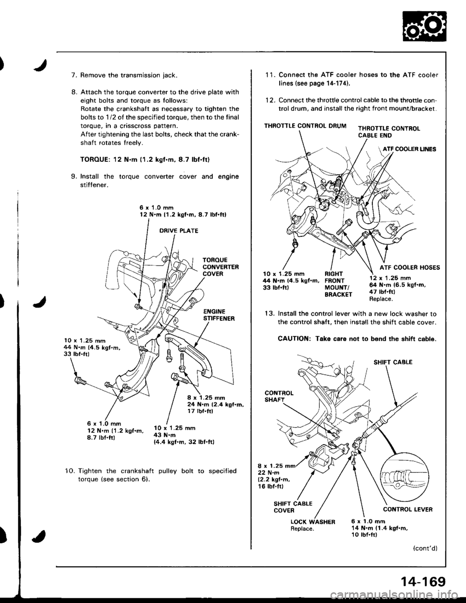
Remove the transmission jack.
Attach the torque converter to the drive plate with
eight bolts and torque as lollows:
Rotate the crankshatt as necessary to tighten the
bolts to 1/2 of the specified torque, then to the final
torque, in a crisscross pattern.
After tightening the last bolts, check that the crank-
shaft rotates freely.
TOROUE: 12 N.m (1.2 kgf.m. 8.7 lbf.ft)
Install the torque converter cover and engine
stitfener.
6 x 1.0 mm12 N'm l'1.2 kgl.m,8.7 lbl.ftl
ORIVE PLATE
9.
6 x '1.0 mm12 N'm ('1.2 kgf.m,8.7 tbt.fr)
l0 x 1.25 mm43 N.m{4.4 kgf.m, 32 lbl.ftl
10.Tighten the crankshaft
torque (see section 6).
pulley bolt to specified
)
1 1. Connect the ATF cooler hoses to the ATF cooler
lines (see page 14-174).
12. Connect the throttle control cable to the throtrle con,
trol drum, and installthe right front mount/brackel.
THROTTLE CONTROL DRUMTHROTTLE CONTROLCABLE END
ATF COOLER UNES
ATF COOLER HOSESlO x 1.25 mm RIGHT44 N.m 14.5 kgf.m, FRONT33 tbf.ft) MoUNT/BRACKET
13.
LOCK WASHERReplace.6 x 1.0 mft14 N.m (1.4 kgt.m,10 tbf.fr)
12 x 'l ,25 nn64 N.rh 16.5 kgf.m,47 tbt.ft)Replace.
SHIFT CABLE
CONTROL LEVER
(cont'dl
Install the control lever with a new lock washer to
the control shalt, then installthe shift cable cover.
CAUTION: Take care not to b6nd the shitt cable.
8 x 1.2522 N-m12.2 kgt.n.'t6 tbl.tr,
SHIFT CABLECOVER
14-169
Page 587 of 1681
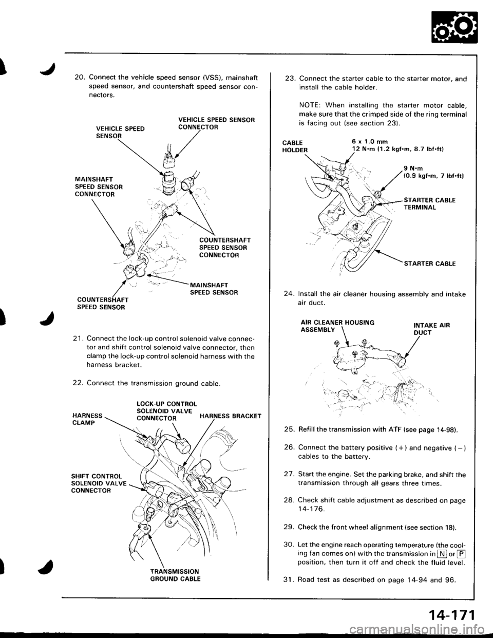
I20.Connect the vehicle speed sensor (VSS), mainshaft
speed sensor, and countershaft sDeed sensor con-
nectors.
VEHICLE SPEED SENSORCONNECTOB
)
k/
t"J
21. Connect the lock-up control solenoid valve connec-
tor and shift control solenoid valve conneclor, then
clamp the lock-up control solenoid harness with the
harness bracket.
22. Connect the transmission ground cable.
SPEED SENSOR
LOCK-UP CONTROLSOLENOID VALVECONNECTOR
23.Connect the starter cable to the starter motor, and
install the cable holder.
NOTE: When installing the starter motor cable,
make sure that the crimped side ol the ring terminal
is facing out (see section 23).
6 x 1.0 mm12 N.m {1 .2 kgf.m, 8.7 lbl.ft)
9 N.m(0.9 kgf.m, 7 lbt.ttl
STARTER CABLETERMINAL
STARTER CABLE
24.Install the air cleaner housing assembly and intake
arr oucl.
AIR CLEANER HOUSINGINTAKE AIRASSEMBLY
27.
Refill the transmission with ATF {see page 14-98).
Connect the battery positive (+ ) and negative { - }cables to the battery.
Start the engine. Set the parking brake, and shift the
transmission through all gears three times.
Check shilt cable adjustment as described on page
14-176.
Check the front wheel alignment (see section 18).
Let the engine reach operating temperature (the cool-ing fan comes onl with the transmission in S or @position, then turn it off and check the fluid level.
31. Road test as described on page 14-94 and 96.
25.
26.
24.
29.
30.
14-171
Page 589 of 1681
![HONDA INTEGRA 1998 4.G Workshop Manual 17. Make sure the transmission is in E] position.
Fill the transmission with ATF, and run the engineJor 30 seconds or until approximately one quart isdischarged.
18. Remove the drain hose, and reconn HONDA INTEGRA 1998 4.G Workshop Manual 17. Make sure the transmission is in E] position.
Fill the transmission with ATF, and run the engineJor 30 seconds or until approximately one quart isdischarged.
18. Remove the drain hose, and reconn](/img/13/6069/w960_6069-588.png)
17. Make sure the transmission is in E] position.
Fill the transmission with ATF, and run the engineJor 30 seconds or until approximately one quart isdischarged.
'18. Remove the drain hose, and reconnect the coolerreturn hose to the transmission.
19. Refillthe tiansmission with ATF to the propef level.
FILLER CAP
TOOL MAINTENANCE
1. Empty and rinse after each use. Fill the can withwater and pressurize the can. Flush the dischargeline to ensure that the unit is clean.
2. lf discharge liquid does not foam, the orifice may beblocked.
3, To clean, disconnect the plumbing from the tank atthe large coupling nut,
4. Remove the in-line filter trom the discharge side andclean if necessary.
5. The fluid oritice is located behind the filter.
Clean it with the pick stored in the bottom of the tankhandle or blow it clean with air. Securely reassem-
ble all parts.
COUPLING NUT
FILTER
\
IO-RINGORIFICE
14-173
Page 592 of 1681
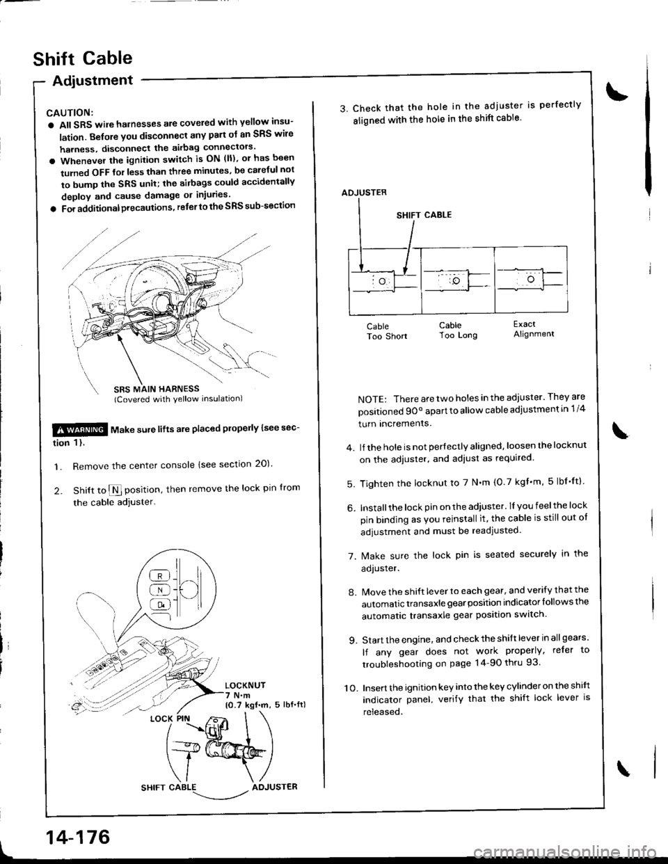
Adiustment
CAUTION:
a All SRS wile harnesses are covered with yellow insu-
lation. Belore you disconnect any part ol an SRS wire
harness, disconnect the akbag connectors'
a Whenever the ignition switch is ON (ll), or has been
tumed OFF tol less than three minutes, be caletul not
to bump the SRS unit; the airbags could accidentally
deploy and cause damage or injuries'
a For additionalprecautions, referto the SRS sub-section
SBS MAIN HARNESS(Covered with yellow inslrlationl
$!@ rtl"t . "ure lifts are placed plope y lsee sec-
tion 1 l.
'1. Remove the center console lsee section 20)'
2. Snitt to $ position, then remove the lock pin lrom
the cable adjuster'
LOCKNUT7 N.m10.7 kgf.m, 5 lbf.fl)
t
]H
@
@
@
{l
LOCK PIN
14-176
shift cable
3. Check that the hole in the adjuster is perfectly
sligned with the hole in the shift cable'
CableToo Short
NOTE: There are two holes in the adjuster. They are
positioned 9Oo apart to allow cable adiustment in 1/4
turn Incremenrs.
4. lJ the hole is not per{ectly aligned, loosen the locknut
on the adjuster, and adiust as required.
5. Tighten the locknut to 7 N'm (0.7 kgf'm, 5lbf'ftl
6. Installthe lock pin on the adiuster. lI you feelthe lock
pin binding as Vou reinstall it, the cable is still out ot
adjustment and must be readjusted.
7. [/ake sure the lock pin is seated securely in the
aoJusrer.
8. Move the shift lever to each gear, and verify that the
automatic transaxle gear position indicator follows the
automatic transaxle gear position swatch.
9. Start the engine, and check the shift lever in allgears'
lf any gear does not work properly, refer to
troubleshooting on page 14-90 thru 93.
10. Insert the ignition key into the key cylinder on the shift
indicator panel, verify that the shift lock lever is
released.
CableToo Long
ExactAlignment
\
ADJUSTER
Page 595 of 1681
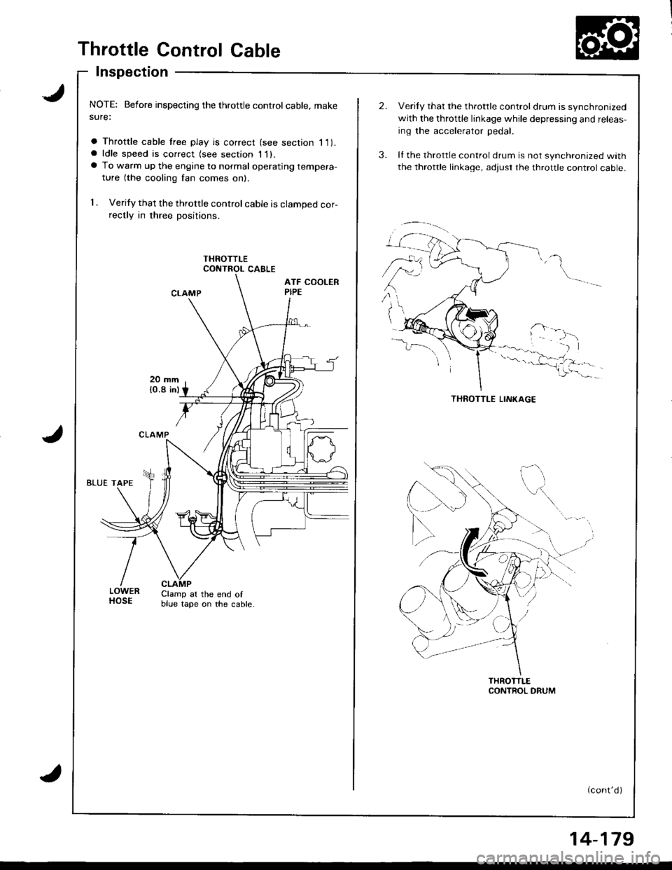
Throttle Control Cable
Inspection
NOTE: Before inspecting the throttle controlcable, makesure:
a Throttle cable tree play is correct (see section I 1).a ldle speed is correct (see section 1l).a To warm up the engine to normal operating tempera-
ture (the cooling fan comes on).
1 . Verify that the throttle control cable is clamped cor-rectly in three positions.
CONTROL CABLE
LOWERHOSEClamp at the end ofblue tape on the cable.
Verily that the throttle controldrum is synchronized
with the throttle linkage while depressing and releas-
ing the accelerator pedal.
ll the throttle control drum is not synchronized with
the throttle linkage, adjust rhe throttle control cable.
(cont'd)
14-179
Page 597 of 1681
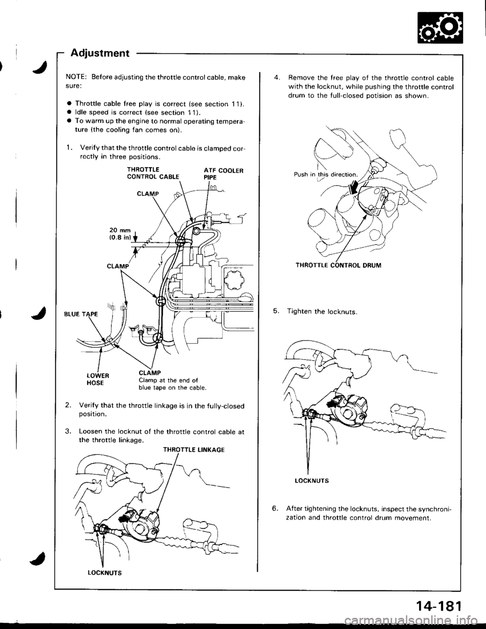
Adjustment
NOTE: Before adjusting the throttle controlcable, make
sure:
a Throttle cable lree play is correct (see section 11).a ldle speed is correct (see section 11).a To warm up the engine to normal operating tempera-
ture {the cooling fan comes on)
1 . Verify that the throttle control cable is clamped correctly in three positions.
THROTTLEATF COOLERPIPE
LOWERHOSEClamp at the end ofblue tape on the cable.
Verily that the throttle linkage is in the fully-closedposttron.
Loosen the locknut of the throttle control cable at
the throttle linkage.
CONTROL CABLE
LOCKNUTS
14-181
Push in this directron.
Remove the free play of the throttle control cable
with the locknut, while pushing the throttle control
drum to the tull-closed potision as shown.
5. Tighten the locknuts.
6.After tightening the locknuts, inspect the synchroni-
zation and throttle control drum movement.
Page 598 of 1681
)
Differential
Manual Transmission
81881 engine ...................................... 15-1
818C1 engine ...................................... 15-9
818C5 engine .....,........... 15-19
Automatic Transmission .................. ..... 15-27