engine HONDA INTEGRA 1998 4.G Workshop Manual
[x] Cancel search | Manufacturer: HONDA, Model Year: 1998, Model line: INTEGRA, Model: HONDA INTEGRA 1998 4.GPages: 1681, PDF Size: 54.22 MB
Page 599 of 1681
Differential (818B1 engine)
Special Tools ........ ........ 15-2
Differential
lllustrated Index......... . 15-3
Backfash Inspection .... 15-4
Final Driven Gear Replacement ...... 15-4
Bearing Replacement .................... 1 5-5
Oil Seal Removal ........ 15-5
Side Clearance Adjustment ........... 15-6
Oil Seal Installation .-... 15-8
t
Page 601 of 1681
Differential (81 881 engine)
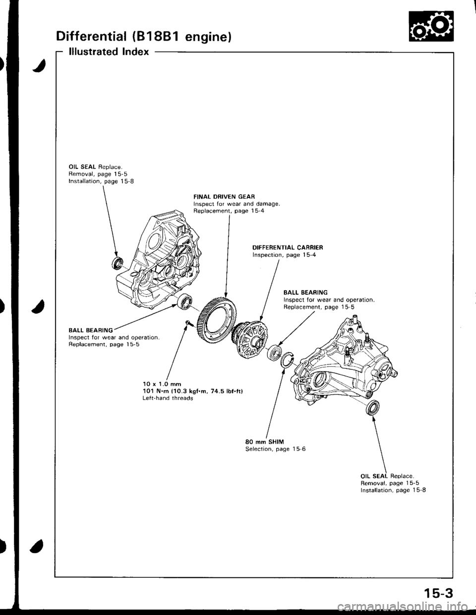
lllustrated Index
t
OIL SEAL Replace.Removal, page 15-5Installation, page 15-8
FINAL DRIVEN GEARInspect for wear and damage,Replacement, page 15-4
DIFFEBENTIAL CARRIERInspection, page 15-4
BALL BEARINGInspect for wear and operation.Replacement, page 15 5
BALL BEARINGInspect for wear and operation.Replacement, page 15-5
10 x 1.0 mm101 N'm 110.3 kgt.m, 74.5 lbt'tt)Lefahand threads
80 mm SHIMSelection, page 15 6
Removal, page 15-5Insrallation, page 1 5-8
15-3
Page 602 of 1681

Differential (81881 engine)
Backlash Inspection
Place differential assembly on V-blocks and install
both axles.
N4easure the backlash ot both pinion gears
Standa.d (Newl: O.O5-0.15 mm (O.OO2-0.006 in)
3. It the backlash is not within the standard, replace
the differential carrier.
Final Driven Gear RePlacement
1. Remove the bolts in a crisscross pattern ln several
steps, then remove the linal driven gear trom the
differential carrier.
NOTE: The final driven gear bolts have left-hand
tnreaos.
10 x 1.0 mm101 N'm 110.3 kgf'm, 74.5 lbf'fll
Left-hand threads
FINAL DRIVEN GEAR
OIFFERENTIALCARRIER
Install the final driven gear by tightening the bolts
in a crissc.oss pattern in several steps.
OIAL INDICATOR
Charnfer on inside diameter ottinal driven gear faces carrier.
\
15-4
Page 604 of 1681
Differential (81 8BJ engine)
Side Clearance Adjustment
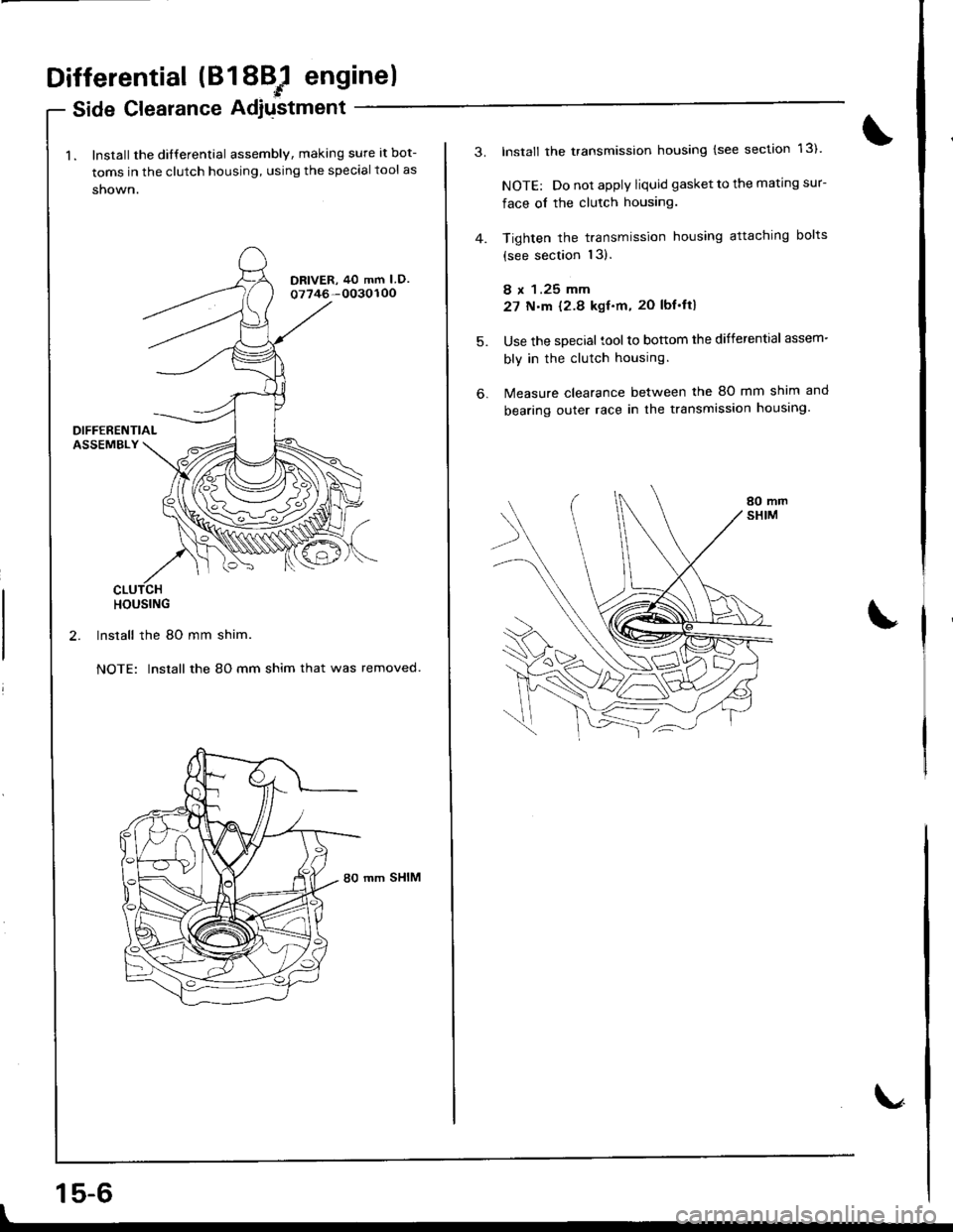
1. lnstall the dilferential assembly, making sure at bot-
toms in the clutch housing, using the special tool as
shown.
DRIVER, 40 mm I D.o7746-0030100
HOUSING
2. Install the 80 mm shim.
NOTE: Insrall the 80 mm shim that was removed.
mm SHIM
15-6
3.Install the transmission housing (see section 13).
NOTE: Do not apply liquid gasket to the mating sur-
face of the clutch housing.
Tighten the transmission housing attaching bolts
{see section l3}.
8 x 1.25 mm
27 N.m {2.8 kgf.m. 20 lbf'ft}
Use the special tool to bottom the differential assem-
bly in the clutch housing.
Measure clearance between the 80 mm shim and
bearing outer race in the transmission housing.
5.
6.
Page 606 of 1681
Differential (81881 engine)
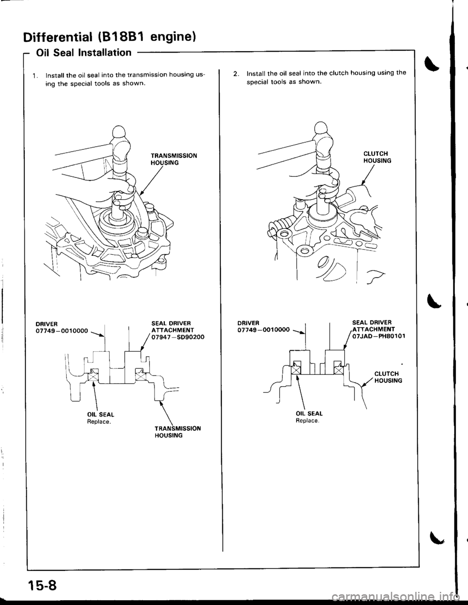
Oil Seal Installation
1. lnstall the oil seal into the transmission housing us-
ing the special tools as shown
DRIVER07749-0010000
OIL SEALReplace.
HOUSING
15-8
Install the oil seal into the clutch housing using the
special tools as shown.
ORIVER07749-OO10000
OIL SEALReplace.
Page 607 of 1681
Differential (818C1 engine)
Special Tools ........ ........ 15-10
Differential
lllustrated Index......... . 15-11
Backfash Inspection .,.. 15-12
Finaf Driven Gear Replacement ...... 15-12
Tapered Roller Bearing Replacement. 15-13
Oil Seal Removal ........ 15-13
Bearing Outer Race Replacement ... 15-14
Tapered Roller Bearing Preload
Adjustment ............. 15-15
Oif Seaf Installation ..... 15-17
Page 609 of 1681
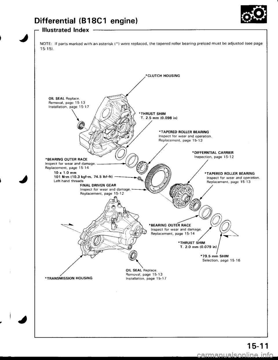
Differential (B18C1 engine)
lllustrated Index
J
J
NOTE: lI parts marked with an asterisk {*)were replaced, the tapered roller bearing preload must be adjusted (see page
15 15).
*CLUTCH HOUSING
OIL SEAL Replace.Removal, page 15 13Installation, page 15 17
*THRUST SHIMT. 2.5 mm {0.098 in)
*TAPERED ROLLER BEARINGlnsDect for wear and ooeration.Replacement, page 1 5-13
*BEARING OUTER RACEInspect for wear and damage.Replacemenl, page 15 14
10 x 1.0 mm
*DIFFERNTIAL CARRIERInspection, page 15-12
101 N.m {'10.3 kgf.m, 74.5 lbf.It)Le{t hand threads
*TAPERED ROLLER BEARINGInspect tor wear and operation.Replacement, page 15 13FINAL DRIVEN GEARInspect tor wear and damage. -----------r'
Repfacement. page 15-1 2
}BEARING OUTER RACE
*79.5 mm SHIMSelection, page 15 16
*TRANSMISSION HOUSING
OIL SEAL Replace.Removal, page 15-13Installation, page 1 5-17
.la
15-1 1
Page 610 of 1681
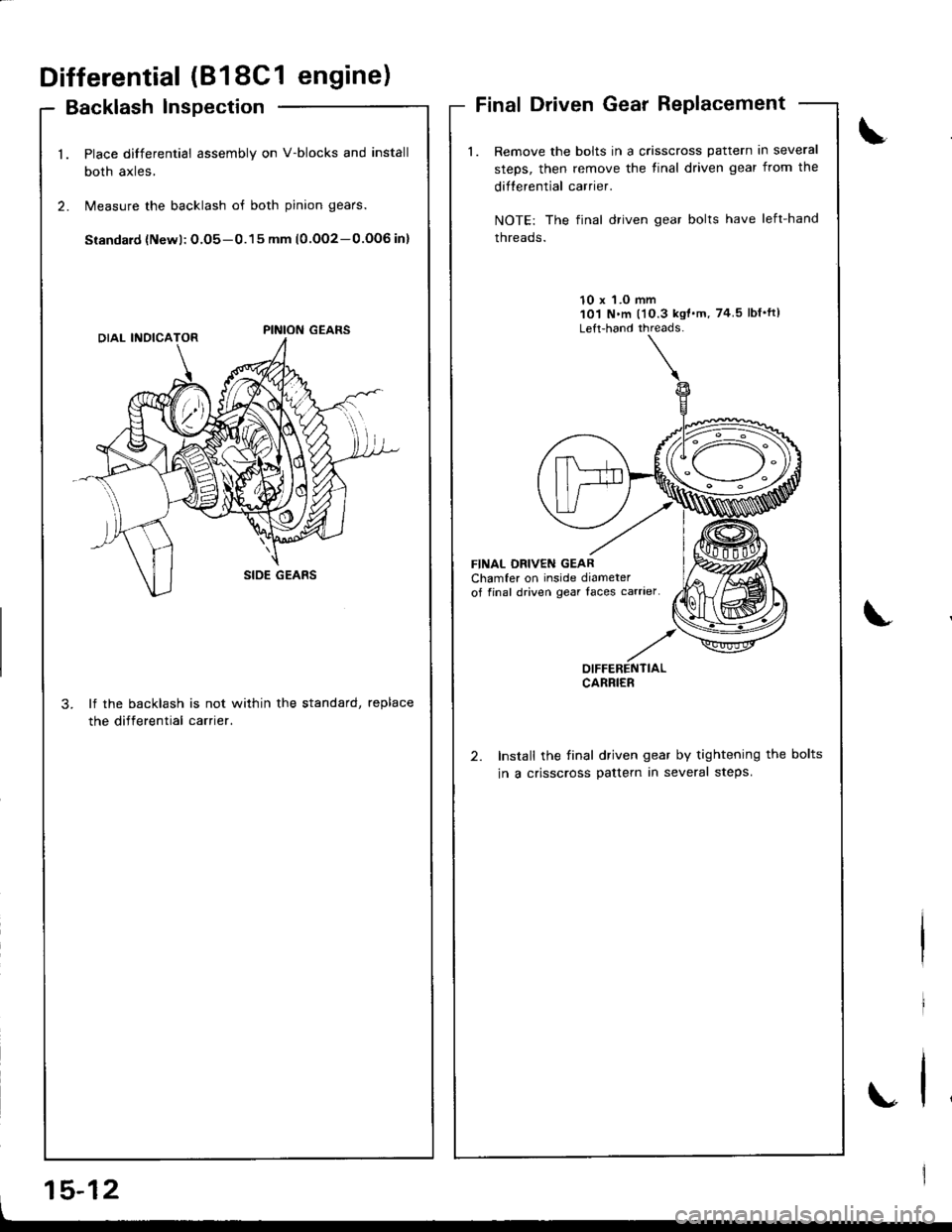
Differential (818C1 engine)
Backlash lnspection
Place differential assembly on V-blocks and install
both axles,
Measure the backlash of both pinion gears.
Siandard {Newl: O.O5-0.15 mm (0.OO2-0.OOG in}
lf the backlash is not within the standard, replace
the differential carrier.
Final Driven Gear Replacement
Remove the bolts in a crisscross pattern in several
steps, then remove the tinal driven gear from the
difterential carrier.
NOTE: The final driven gear bolts have left-hand
threads.
10 x 'l.O mm101 N.m l'10.3 kgt'm, 74 5lbf'ft)
Left-hand threads-
FINAL DBIVEN GEARChamfer on inside diameterof final driven gear Iaces carrier
Install the final driven gear by tightening the bolts
in a crisscross pattern in several steps.
\
.,
OIFFERENTIALCARRIER
I
15-12
Page 612 of 1681
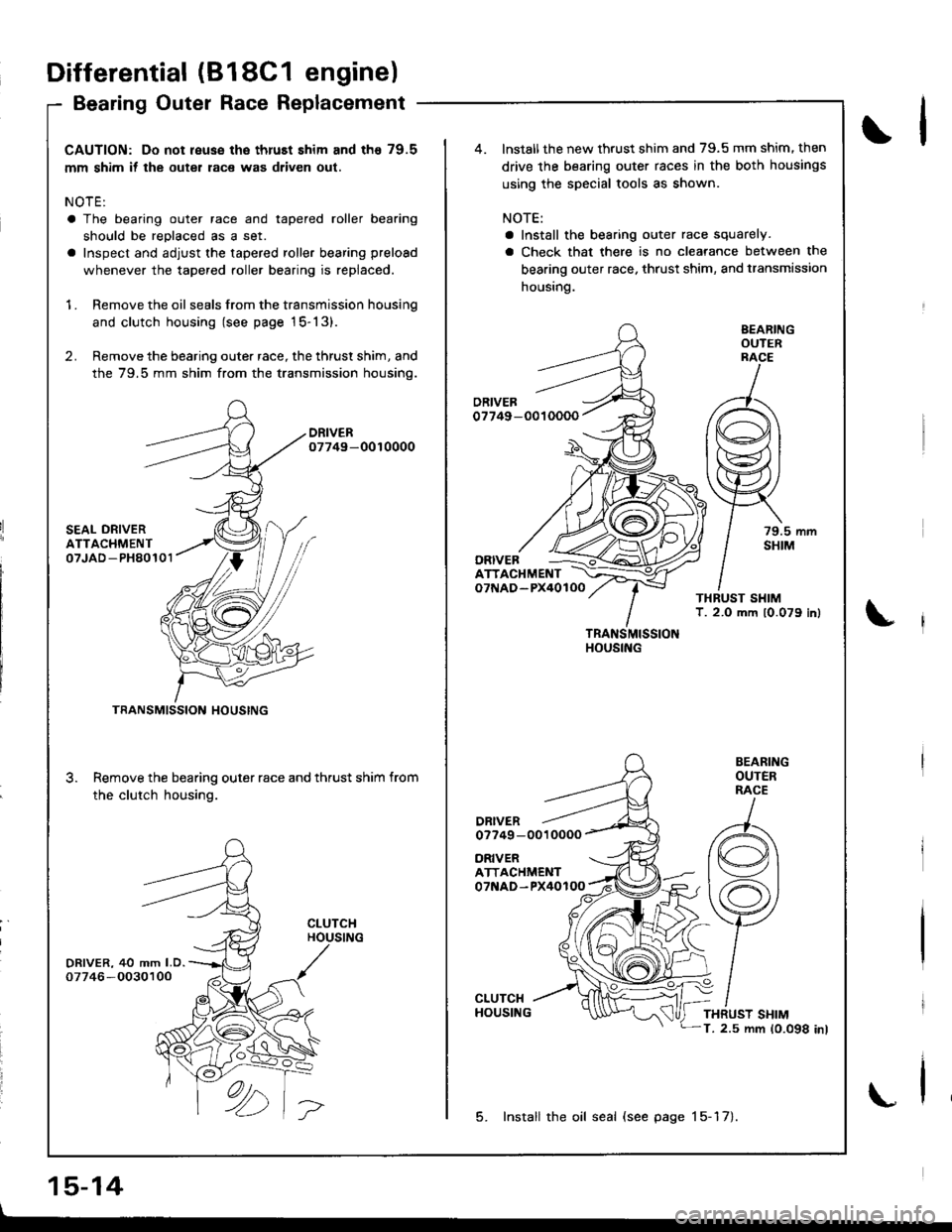
CAUTION: Do not reuse the thruEt shim and th€ 79.5
mm shim if the outer race was driven out.
NOTE:
a The bearing outer race and tapered roller bearing
should be reDlaced as a set.
a Inspect and adjust the tapered roller bearing preload
whenever the tapered roller bearing is replaced.
1 . Remove the oil seals from the transmission housing
and clutch housing (see page 15-13).
2. Remove the bearing outer race, the thrust shim, and
the 79.5 mm shim from the transmission housino.
DRIVER07749-0010000
SEAL ORIVERATTACHMENT07JAD -PH80101
DRIVER, 40 mm LD.07746 -O030100
3.
TRANSMISSION HOUSING
Remove the bearing outer race and thrust shim from
the clutch housing.
CLUTCHHOUSING
ORIVERATTACHMENT07NAD-PX40100
ATTACHMENTo7f{AD-PX40lOO
DRIVERo7749 -0010000
TRANSMISSIONHOUSING
BEARINGOUTERRACE
79.5 mmSHIM
BEARINGOUTERRACE
THRUST SHIMT. 2.5 mm 10.098 inl
lnstall the new thrust shim and 79.5 mm shim. then
drive the bearing outer races in the both housings
using the special tools as shown.
NOTE:
a Install the bearing outer race squarely.
a Check that there is no clearance between the
bearing outer race. thrust shim, and transmission
housing.
ORIVEB
5. Install the oil seal (see page 15-17).
Differential (818C1 engine)
Bearing Outer Race Replacement
15-14
\l
\
\
Page 614 of 1681
Differential
Ted Roll
(B18C1
er Bearinr
engine)
Preload Adjustment (cont'd)aperelng
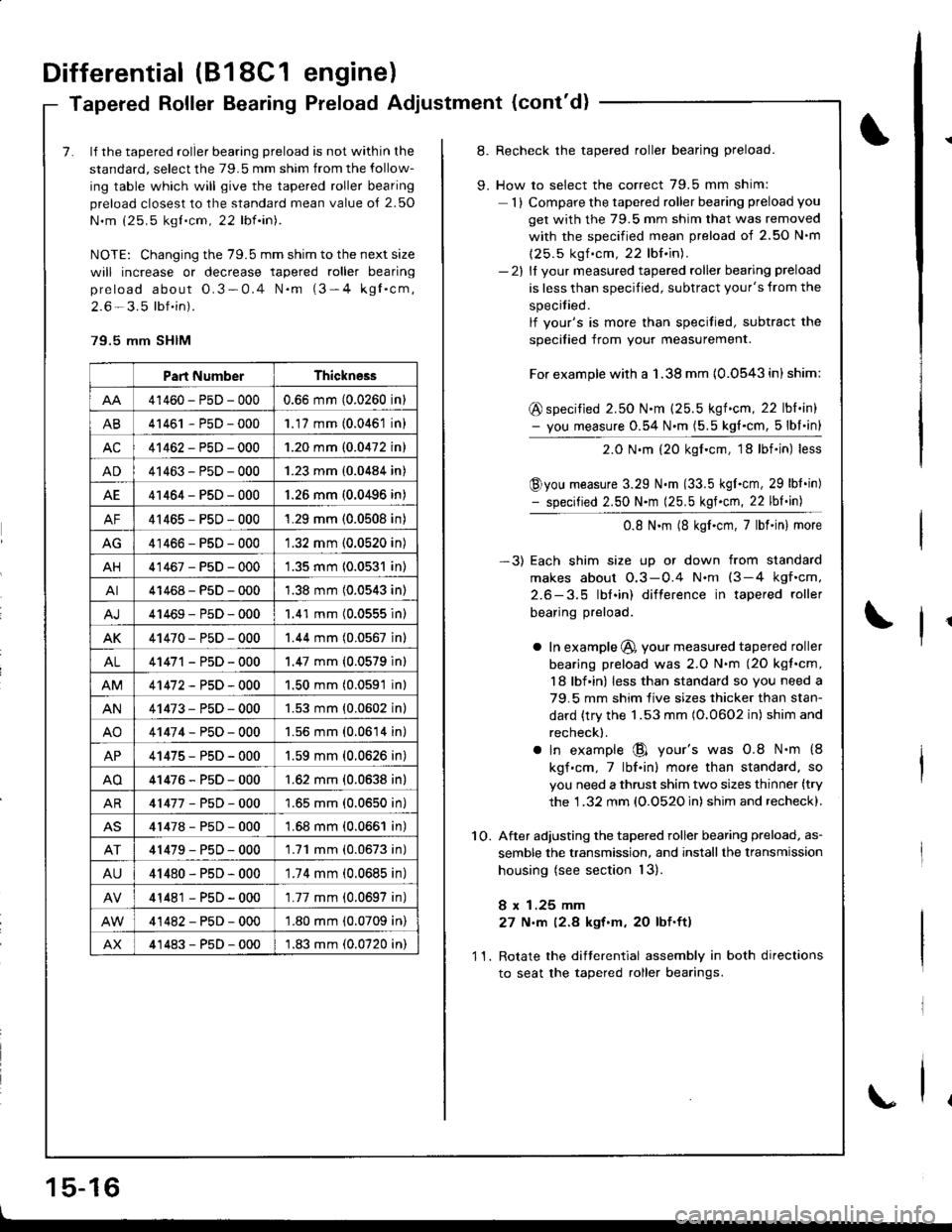
7. lf the tapered roller bearing preload is not within the
standard, select the 79.5 mm shim from the follow-
ing table which will give the tapered roller bearing
preload closest to the standard mean value o{ 2.50
N.m (25.5 kgt.cm, 22 lbf.in).
NOTE: Changing the 79.5 mm shim to the next size
will increase or decrease tapered roller bearing
preload about O.3-0.4 N.m (3-4 kgl.cm,
2.6 - 3.5 lbf.in).
79.5 mm SHIM
Part NumberThickness
41460-PsD-0000.66 mm (0.0260 in)
AB41461 - P5D - 0001.17 mm (0.0461 in)
AC41462-PsD-0001.20 mm (0.0472 in)
AD41463-P5D-0001.23 mm (0.0484 in)
AE41464-PsD-000'1.26 mm (0.0496 in)
AF41465-PsD-0001.29 mm (0.0508 in)
AG41466-PsD-0001.32 mm (0.0520 in)
AH41467-PsD-0001.35 mm 10.0531 in)
AI41468-PsD-0001.38 mm (0.0543 in)
41469-P5D-0001.41 mm (0.0555 inl
AK41470-PsD-0001.44 mm (0.0567 in)
AL41471 - PsD - 000'1.47 mm {0.0579 in}
41472-P5D-0001.50 mm (0.0591 in)
AN41473-PsD-0001.53 mm {0.0602 in}
AO41474-P50-0001.56 mm (0.0614 in)
AP41475-PsD-0001.59 mm (0.0626 in)
AO41476-P5D-000'1.62 mm {0.0638 in}
AR41477-P5D-0001.65 mm (0.0650 in)
41478-P5D-0001.68 mm (0.0661 in)
41479-P50-0001.71 mm (0.0673 in)
AU41480-PsD-0001.74 mm (0.0685 in)
41481 - PsD - 000'1.77 mm (0.0697 in)
41482-PsD-000'1.80 mm (0.0709 in)
AX41483-P5D-0001.83 mm (0.0720 in)
8. Recheck the tapered roller bearing preload.
9. How to select the correct 79.5 mm shim:
1) Compare the tapered roller bearing preload you
get with the 79.5 mm shim that was removed
with the soecified mean Dreload of 2.50 N'm
(25.5 kgf .cm, 22 lbf.in).- 2l ll vour measured tapered roller bearing preload
is less than specified, subtract your's from the
specitied.
lf vour's is more than specitied, subtract the
soecified from vour measurement.
For example with a 1.38 mm {0.0543 in) shim:
@ specified 2.50 N.m (25.5 kgf.cm, 22 lbl.in)- you measure 0.54 N.m (5.5 kg{.cm, 5lbl.in}
2.0 N.m (20 kgf.cm, 18lbf.in) less
@you measure 3.29 N.m (33.5 kgI.cm, 29 lbt.in)- specified 2.50 N.m (25.5 kgf.cm, 22 lbf.in)
0.8 N.m (8 kgf.cm,7lbf.in) more
-3) Each shim size up or down from standard
makes about O.3-0.4 N.nt (3-4 kgf.cm,
2.6-3.5 lbl.in) difterence in tapered roller
bearing preload.
a In example @, your measured tapered roller
bearing preload was 2.O N.m (2O kgt.cm,
18 lbf in) less than standard so you need a
79.5 mm shim live sizes thicker than stan-
dard {try the 1.53 mm (O.0602 in) shim and
recheck).
a ln example @ your's was 0.8 N.m {8
kgf.cm,7lbf.in) more than standard. so
you need a thrust shim two sizes thinner (try
the 1 .32 mm (O.O52O in) shim and recheck).
1O. After adjusting the tapered roller bearing preload, as-
semble the transmission, and installthe lransmission
housing (see section 13).
8 x 1.25 mm
27 N,m (2.8 kgt'm, 20 lbf.ft)
11. Rotate the difterential assembly in both directions
to seat the tapered roller bearings.
1 5-16
\