engine HONDA INTEGRA 1998 4.G Workshop Manual
[x] Cancel search | Manufacturer: HONDA, Model Year: 1998, Model line: INTEGRA, Model: HONDA INTEGRA 1998 4.GPages: 1681, PDF Size: 54.22 MB
Page 616 of 1681
Differential (818C5 engine)
SpecialTools .......... ........... 15-20
Limited Slip Differential
Description ..................... 15-21
OperationalGheck ......... 15-23
Rotating Torque Gheck .15-23
lffustrated Index .......... ..15-24
Tapered Roller Bearing Preload
Adjustment ................. 15-25
Page 618 of 1681
Limited Slip Differential (818C5 engine)
Description
t
f1t
1. Function
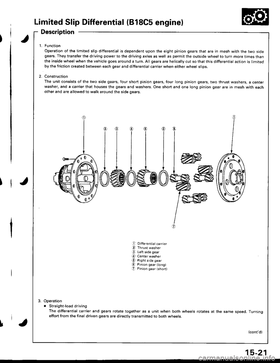
Operation of the limited slip differential is dependent upon the eight pinion gears that are in mesh with the two sidegears. They transfer the driving power to the driving axles as well as permjt the outside wheel to turn more times thanthe inside wheel when the vehicle goes around a turn. All gears are helically cut so that this differential action is limitedby the friction created between each gear and differential carrier when either wheel slips.
2. Construction
The unit consists of the two side gears, four short pinion gears, four long pinion gears, two thrust washers, a centerwasher, and a carrier that houses the gears and washers. One shon and one long pinion gear are in mesh with eachother and are allowed to walk around the side oears.
w
I
I
I
+
@
a,
e Differentiatcarrier
a Thrust washer
@ Left side gear
O Center washerg Right side gear
O Pinion gear ong)O Pinion gea r (short)
Ooeration
. Straight-load driving
The differential carrier and gears rotate together as a unit when both wheels rotates at the same speed. Turningeffon from the final driven gears are directly transmitted to both wheets.
(cont'd)
l,'a
15-21
Page 619 of 1681
Limited Slip Differential (B18C5 engine)
Description (cont'd)
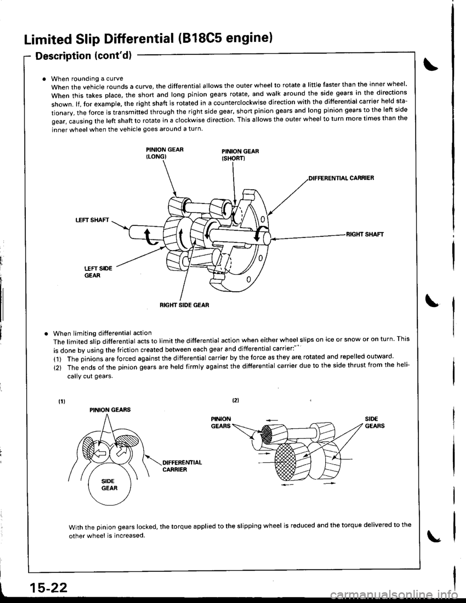
When roundang a curve
When the vehacle rounds a curye, tne differential allows the outer wheel to rotate a little faster than the inner wheel.
when this takes p|ace. the short and |ong pinion gears rotate, and wa|k around the side gears in the directions
shown. lf, for example. the right shaft is rotated in a counterclockwise direction with the differential carrier held sta-
tionary, the force is transmitted through the right side gear, short pinion gears and long pinion gears to the left side
gear, causing the left shaft to rotate in a clockwise direction. This allows the outer wheel to turn more times than the
inner wheel when the vehicle goes around a turn.
PINION GEARILONG)
When limiting differential action
The limited slip differential acts to limit the differential action when either wheel slips on ice or snow or on turn. This
is done by using the friction created between each gear and differential carrier:"''
(1) The pinions are forced against the differential carrier by the force as they are- rotated and repelled outward.
(2) The ends of the pinion gears are held firmly against the differential carrier due to the side thrust from the heli-
callY cut gears.
CARRIEB
TTFT SHAFT
RIG}IT SHAFT
With the pinion gears locked, the torque applied to the slipping wheel is reduced 8nd the torque delivered to the
other wheel is increased.
tzl
t15-22
RIGHT SIDE GEAR
PINION GEARS
Page 620 of 1681
Operational Check
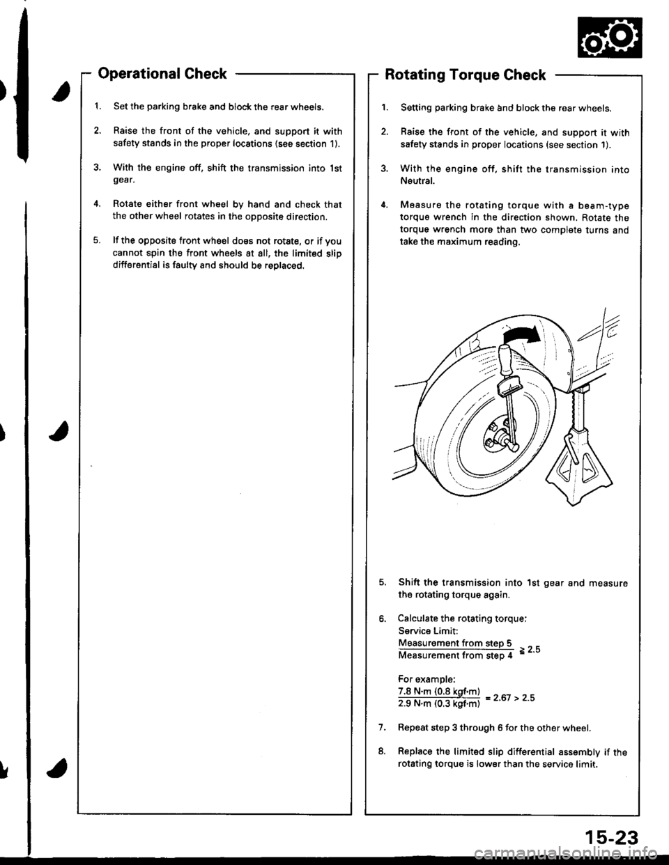
Set the parking brake and block the rear wheels.
Raise the front of the vehicle, and support it with
safety stands in the proper locations (see section 1).
With the engine off, shift the transmission into lstgear,
Rotate either front wheel bv hand and check that
the other wheel rotates in the opposite direction.
lf the opposite tront wheel does not rotste, or if voucannot spin the front wheels at all, the limited slip
differential is faulty and should be roplaced.
Rotating Torque Check
Setting parking brake and block the rear wheels.
Raise the front of the vehicle, and support it with
safety stands in proper locations (see section 1).
With the engine off, shift the transmission into
Neutral.
Measure the rotating torque with a beam-type
torquo wrench in the direction shown, Rotate the
torque wrench morg than two complete turns and
take the maximum reading.
Shift the transmission into 1st gear and measure
the rotating torque again.
Calculate the rotating torque:
Service Limit:
Measur€ment from steD 5
Measurementfrom step 4 =--
For example:
7.8 N.m (0.8 kgf.m)
zg N"ll (03 kgf'ntl = z'ot > z''
Repeat step 3 through 6 for the other wheel.
Replace the limited slip differential assembly if the
rotsting lorque is lower than the service limit.
!
15-23
Page 621 of 1681
Limited Slip Differential (B18C5 engine)
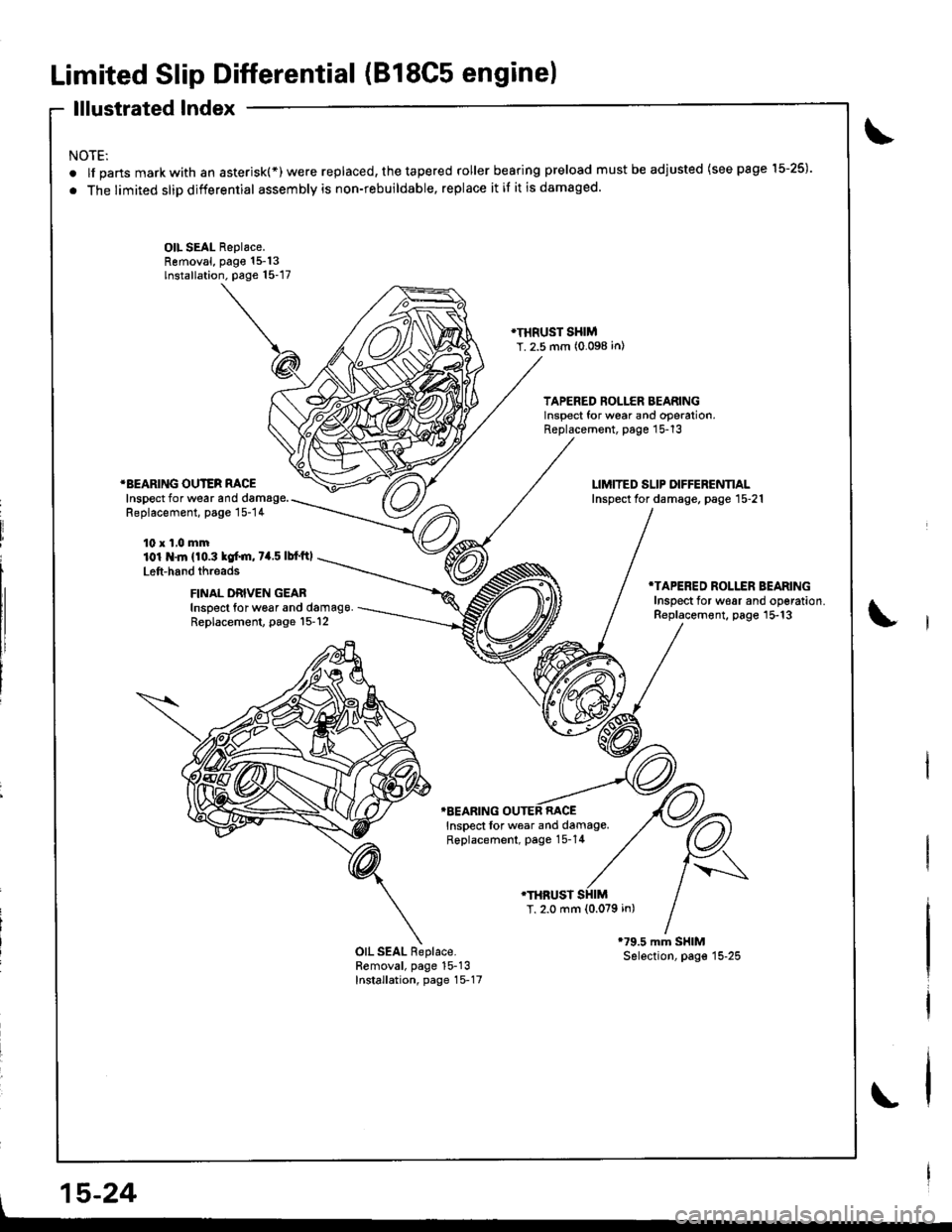
lllustrated Index
NOTE:
.lfpartsmarkwithanasterisk(*)werereplaced,thetaperedrollerbearingpreloadmustbeadjusted(seepagel5-25).
. The limited slip differential assembly is non-rebuildable, replace it if it is damaged.
OIL SEAL Replace.Removal, page 15-13lnstallation. page 15-17
}I}IRUST SHIMT. 2.5 mm (0.098 in)
TAPERED ROLLER BEARINGlnsoect for wear and ooeration,Replacement, page 15-13
*BEARING OUTER RACEInspect for wear and damage.Replacement, page 15-14
10 x 1,0 mm101 .ln {10.3 kof.m, 7a.5 lbf'ftl
Left-hand threads
FINAL DRIVEN GEABInspect for w6ar and damag9.Replacement, page l5-12
*TAPERED ROLLER BEARINGInsDect for w€ar and oo€ration.Replacement, page 15-13
TBEARING OUTEB RACEInspect lor wear and damage.Replacement, page 15-14
.THRUST
T, 2.0 mm {0.079 in)
OIL SEAL Replace.Removal, page 15-13Installation, page 15-17
l,
, 15-24
Page 623 of 1681
Limited Slip Differential (B18C5 engine)
Tapered Roller Bearing Preload Adiustment (cont'd)
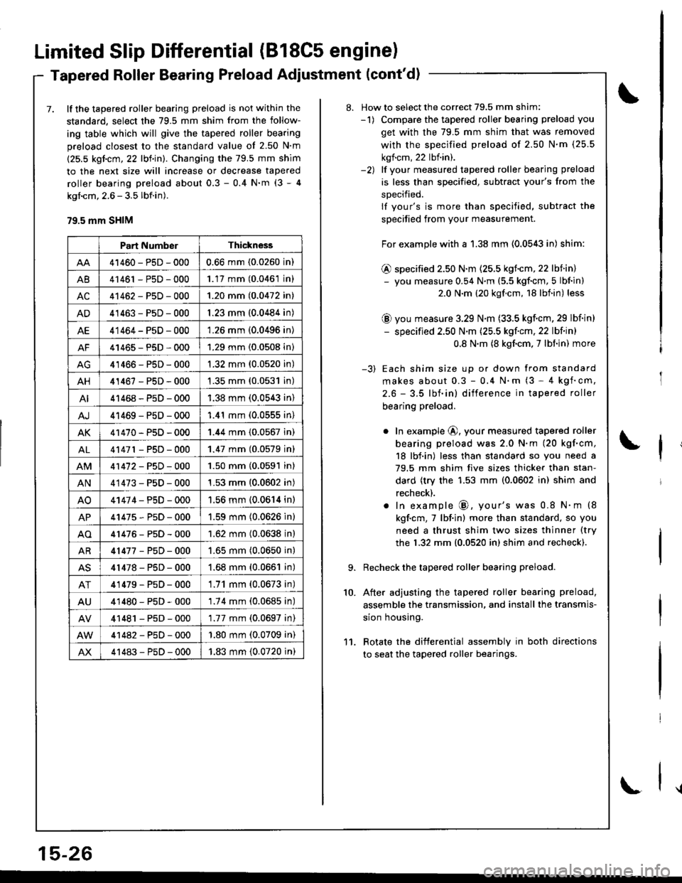
7. lf the tapered roller bearing preload is not within the
standard, select the 79.5 mm shim from the follow-
ing table which will give the tapered roller bearing
preload closest to the standard value of 2.50 N'm
(25.5 kgicm, 22 lbf in). Changing the 79.5 mm shim
to the next size will increase or decrease tapered
roller bearing preload about 0.3 - 0.4 N'm (3 - 4
kgl.cm, 2.6 - 3.5 lbf.in).
79.5 mm SHIM
Part NumberThickness
41460-PsD-0000.66 mm (0.0260 in)
A841461 - P5D - 0001.17 mm (0.0461 in)
AC41462-P5D-0001.20 mm (0.0472 in)
AD41463-P5D-0001.23 mm (0.0484 in)
AE41464-P5D-0001.26 mm (0.0496 in)
AF41465-P5D-0001.29 mm (0.0508 in)
41466-PsD-0001.32 mm (0.0520 in)
AH41467-PsD-0001.35 mm (0.0531 in)
AI41468-P5D-0001.38 mm (0.0543 in)
AJ41469-PsD-0001.41 mm (0.0555 in)
AK41470-PsD-0001.44 mm (0.0567 in)
AL41471 - PsD - 0001.47 mm (0.0579 inl
41472-P5D-0001.50 mm (0.0591 in)
AN41473-P5D-0001.53 mm (0.0602 in)
AO41474-PsD-0001.56 mm (0.0614 in)
AP41475-P5D-0001.59 mm (0.0626 in)
AO41476-P5D-0001.62 mm (0.0638 in)
AR41477-P5D-0001.65 mm (0.0650 in)
AS41478-PsD-0001.68 mm (0.0661 in)
AT41479-P5D-0001.71 mm (0.0673 in)
AU41480-PsD-0001.74 mm (0.0685 in)
41481 - PsD - 0001.77 mm (0.0697 in)
41482-P5D-000'1.80 mm (0.0709 in)
AX41483-P5D-0001.83 mm (0.0720 in)
15-26
\
8. How to select the correct 79,5 mm shim:-1) Compare the tapered roller bearing preload you
get with the 79.5 mm shim that was removed
with the sDecified preload of 2.50 N'm (25.5
kgf.cm, 22 lbf.in).-2) lf vour measured tapered roller bearing preload
is less than specified, subtract your's from the
sDecified.
lf your's is more than specified, subtract the
specified from your measurement.
For example with a 1.38 mm (0.0543 in) shim:
@ specified 2.50 N.m (25.5 kgf.cm,22 lbiin)- you measure 0.54 N.m (5.5 kgf'cm, 5 lbf in)
2.0 N.m (20 kgf.cm, 18 lbf.in) less
@ you measure 3.29 N.m (33.5 kgf.cm, 29 lbf in)
- specified 2.50 N'm (25.5 kgf'cm, 22 lbf in)
0.8 N.m {8 kgf.cm. 7 lbf in) more
-3) Each shim size up or down from standard
makes about 0.3 - 0,4 N.m (3 - 4 kgf'cm,
2.6 - 3.5 lbf.in) difference in tapered roller
bearing preload.
o In example @, your measured tapered roller
bearing preload was 2.0 N.m (20 kgf.cm,
18 lbf.in) less than standard so you need a
79.5 mm shim five sizes thicker than stan-
dard (try the 1.53 mm (0.0602 in) shim and
recheck).
. In example @, your's was 0.8 N.m (8
kgf.cm,7 lbf.in) more than standard, so you
need a thrust shim two sizes thinner (try
the 1.32 mm {0.0520 in) shim and recheck).
Recheck the tapered roller bearing preload.
After adjusting the tapered roller bearing preload,
assemble the transmission, and install the transmis-
sion housing.
Rotate the difterential assembly in both directions
to seat the tapered roller bearings.
10.
11.
Page 642 of 1681
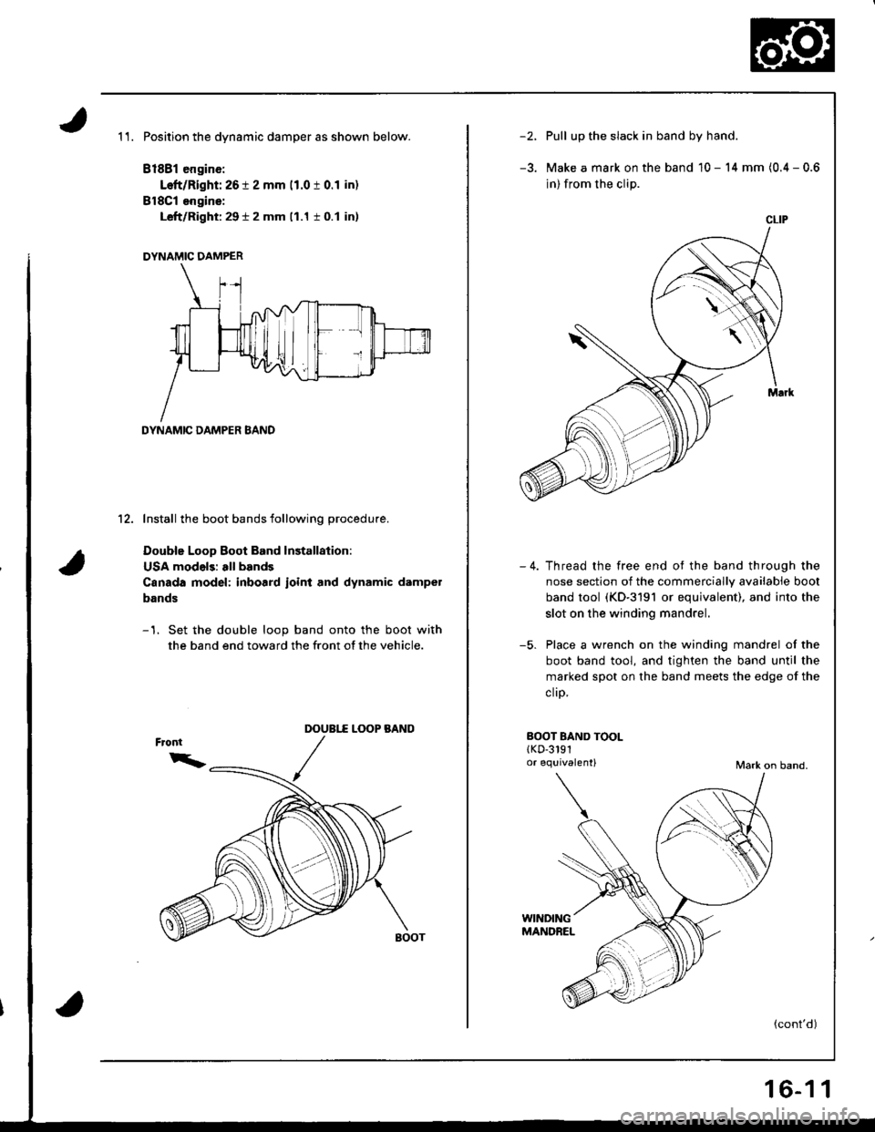
1 1. Position the dynamic damper as shown below.
81881 engine:
Left/Right: 26 t 2 mm 11.0 t 0.1 in)
BlSCl engins:
Left/Right: 29 t 2 mm (1.1 i 0.1 in)
DYNAMIC DAMPER
DYNAMIC DAMPER BAND
12. Install the boot bands following procedure.
Double Loop Boot Band lnstallalion:
USA models: all bands
Canada model: inboard ioint and dynamic dampel
bands
-1. Set the double loop band onto the boot with
the band end toward the front of the vehicle.
L(X)P BANODOUBI.f
/
-')Pull up the slack in band by hand.
Make a mark on the band 10 - 14 mm (0.4 - 0.6
in) from the clip.
Thread the free end ot the band through the
nose section of the commercially available boot
band tool (KD-3191 or equivalent), and into the
slot on the winding mandrel.
Place a wrench on the winding mandrel of the
boot band tool, and tighten the band until the
marked spot on the band meets the edge of the
clrp,
-5.
BOOT BAND TOOLlKD-3191o. equivalent)Mark on band.
(cont'd)
CLIP
16-1 1
Page 653 of 1681
System Description
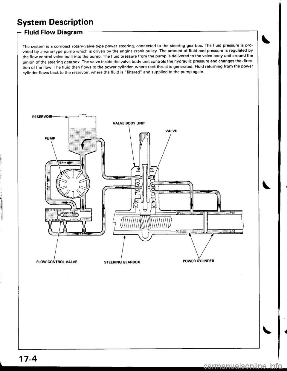
Fluid Flow Diagram
The system is a compact rotary-valve-type power steering, connected to the steering gearbox. The fluid pressure is pro-
vided by a vane-type pump which is driven by the engine crank pulley. The amount of fluid and pressure is regulated by
the flow control valve built into the pump. The fluid pressure from the pump is delivered to the valve body unit around the
pinion of the steering gearbox. The valve inside the valve body unit controls the hydraulic pressure and changes the direc-
tion of the tlow. The fluid then flows to the power cylinder, where rack thrust is generated. Fluid returning from the power
cylinder flows back to the reservoir, where the fluid is "filtered" and supplied to the pump again
li
I
VALVE BODY UNIT
GEARBOXFLOW CONTROL VALVEPOWER CYLINDER
17-4
Page 655 of 1681
System Description
Steering Pump (cont'd) .
17-6
Flow Control
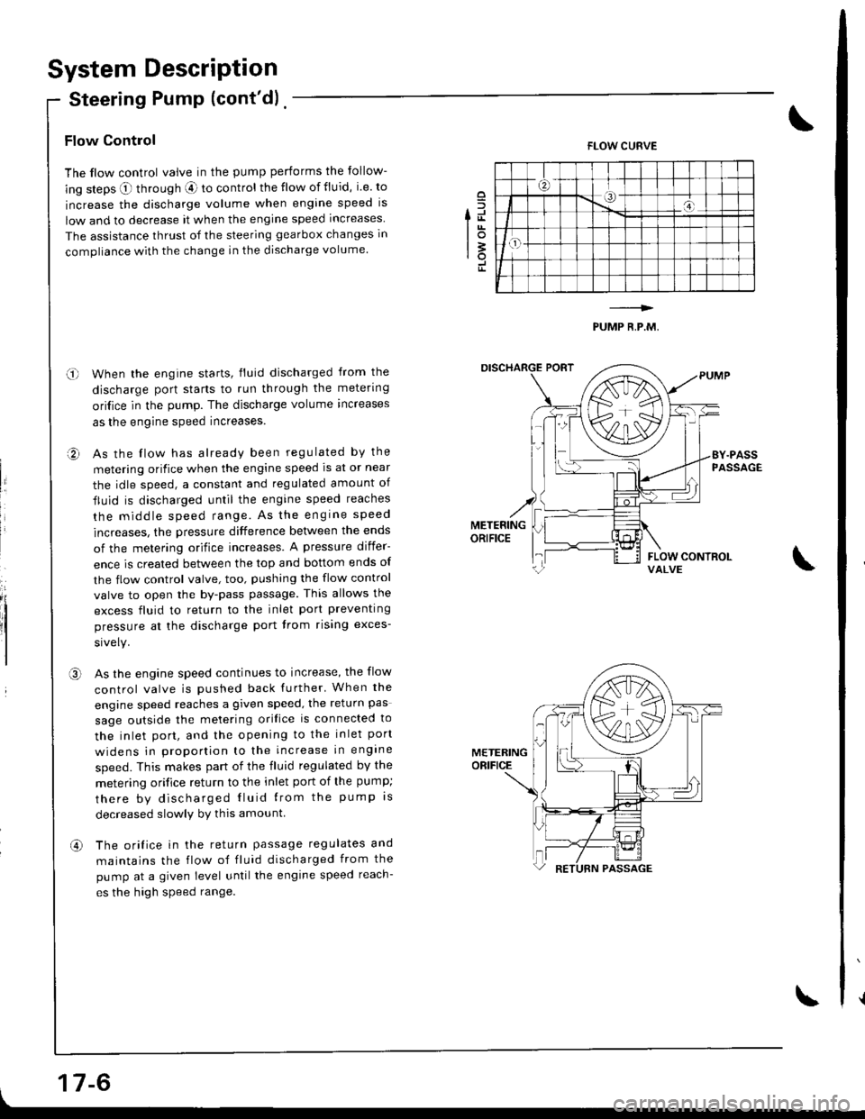
The flow control valve in the pump performs the follow-
ing steps O through aE ro control the flow of fluid, i.e. to
increase the discharge volume when engine speed is
low and to decrease it when the engine speed increases
The assistance thrust of the steering gearbox changes in
compliance with the change in the discharge volume.
When the engine starts, fluid discharged from the
discharge port starts to run through the metering
ori{ice in the pump. The discharge volume increases
as the engine speed increases.
As the flow has already been regulated by the
metering orifice when the engine speed ls at or near
the idle speed, a constant and regulated amount of
fluid is discharged until the engine speed reaches
the middle speed range. As the engrne speed
increases, the pressure difference between the ends
of the metering orifice increases. A pressure differ-
ence is created between the top and bottom ends of
the flow control valve, too, pushing the flow control
valve to open the by-pass passage. This allows the
excess fluid to return to the inlet port preventing
pressure at the discharge port trom rising exces-
As the engine speed continues to increase, the flow
control valve is pushed back further' When the
engine speed reaches a given speed, the return pas
sage outside the melering orifice is connected to
the inlet port, and the opening to the inlet port
widens in prooortion to the increase in engine
speed. This makes part of the fluid regulated by the
metering orifice return to the inlet port of the pump;
there by discharged Iluid lrom the pump rs
decreased slowlv by this amount
The orifice in the return passage regulates and
maintains the flow of fluid discharged from the
pump at a given level untilthe engine speed reach-
es the high speed range.
o
fd
lot3rotr
FLOW CURVE
PUMP R,P.M,
o-l
a,
II
,a\
METERINGORIFICE
an
Page 659 of 1681
Troubleshooting
General Troubleshooting
Check the following before you begin:
o Has the suspension been modified in a way that would affect steering?
. Are tire sizes and air pressure correct?
. lsthe steering wheel original equipment or equivalent?
. ls the power steering pump belt properly adiusted?
. ls steering fluid reservoirtilled to proper level?
. ls the engine idle speed correct and steadyT
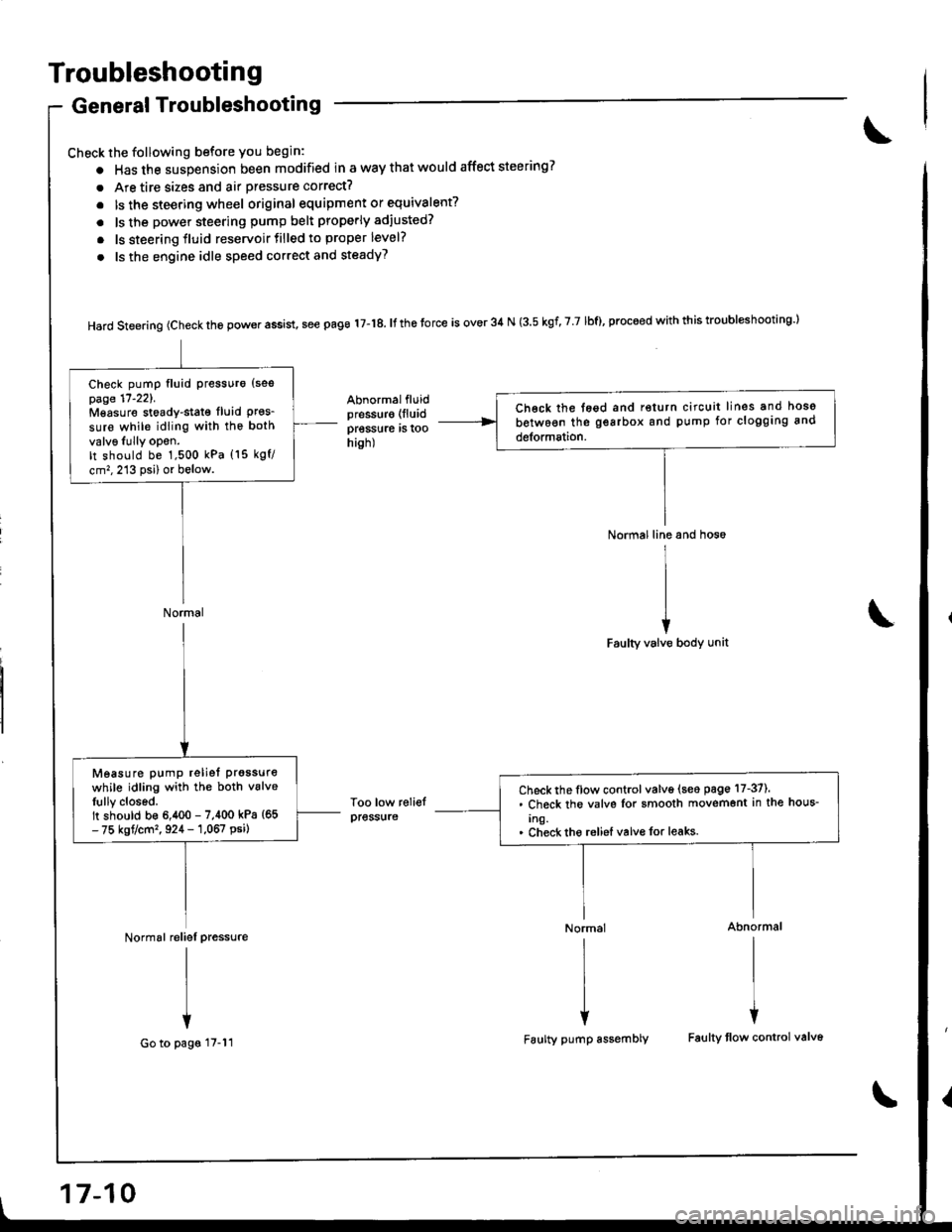
Hard steering (check the power assist, see page 17-18. It the torce is over 34 N (3.5 kgf, 7 7 lbf), proceed with this troubl*hooting l
Abnormalfluidpressur€ (lluid
pressure rs roohish)
Too low reliefpress{ire
Normal line and hos6
I
II
iFaulty valve body unit
Normal Abnormal
rlrl
l{
Faulty pump assembly Faulty tlow control valv6
Ch€ck the tegd and return circuit lines and hoso
between the gearbox and pump for clogging and
detormation.
Check pump fluid Pressuro {sespage 17'221.Mgasure stoady-stat€ fluid Pres_sure while idling with the both
valv6Iully opon.It should be 1,500 kPa (15 kgf/
cm,,213 psi) or below.
Normal
Check the flow control valve (seo page 17-37).. Check the valvs Ior smooth movemont in the hous-
Ing.. Check tho reliel valvo for leaks.
Measure pump reliet prgssure
while idling with the both vslveIully closed.It should b€ 6,400 - 7,400 kPa {65- 75 kgt/cm'�, 924 - 1,067 psi)
Normal reliel pressure
I
I
+
Go to pags 17-11
17-10