lock HONDA INTEGRA 1998 4.G Workshop Manual
[x] Cancel search | Manufacturer: HONDA, Model Year: 1998, Model line: INTEGRA, Model: HONDA INTEGRA 1998 4.GPages: 1681, PDF Size: 54.22 MB
Page 898 of 1681
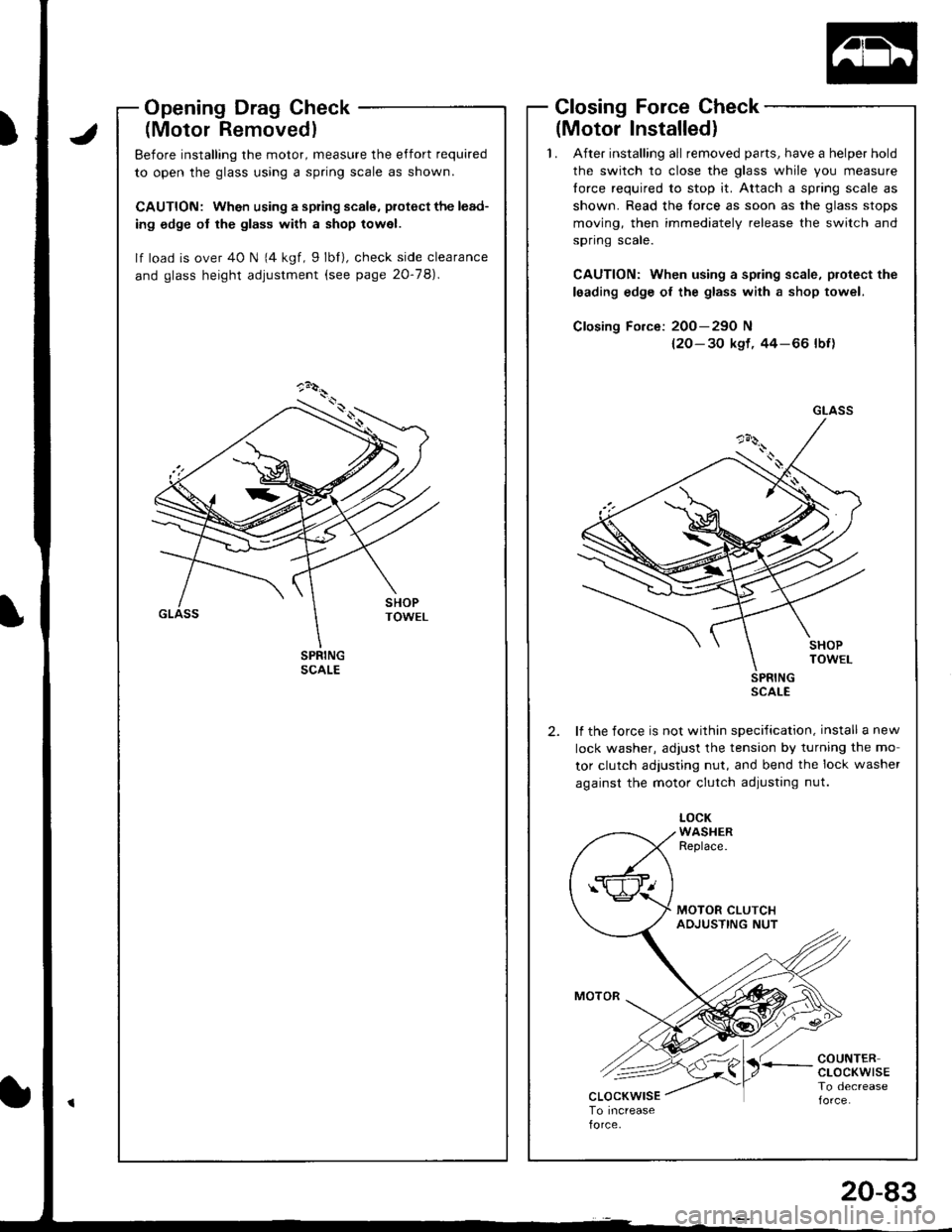
OpeningDragGheck
(Motor Removedl
Before installing the motor, measure the effort required
to open the glass using a spring scale as shown.
CAUTION: Wh€n using a spring scale, piotect the lead-
ing odge of the glass with a shop towel.
lf load is over 40 N 14 kgf, 9lbf), check side clearance
and glass height adjustment (see page 20-78).
Closing Force Check
(Motor Installedl'1. After installing all removed parts, have a helper hold
the switch to close the glass whjle you measure
{orce required to stop it. Attach a spring scale as
shown. Read the force as soon as the glass stops
moving, then immediately release the switch and
spflng scate.
CAUTION: When using a sp.ing scale, protect the
leading edge of the glass with a shop towel.
Closing Fo.ce: 200-29O N
{2O- 30 kst. 44-66 lbf)
SPRINGscAt_E
lf the force is not within specification, install a new
lock washer, adjust the tension by turning the mo
tor clutch adjusting nut, and bend the lock washer
against the motor clutch adjusting nut.
2.
LOCKWASHERReplace.
COUNTERcLocKwtsETo decrease
GLASS
t;-<
20-83
Page 905 of 1681
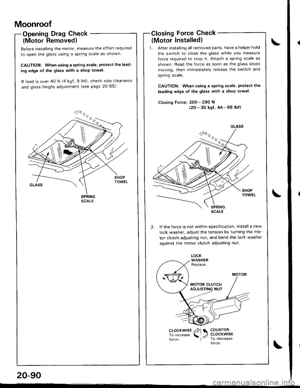
Moonroof
Opening Drag Check
(Motor Removedl
Before installing the motor, measure the effort required
to open the glass using a spring scale as shown.
CAUTION: When using a spring scale, protecl the lead-
ing edge ot the glass with a shop towel.
lf load is over 40 N (4 kgl, 9 lbfi, check side clearance
and glass height adjustment (see page 20-85)
Closing Force Check
{Motor Installed}
'1 . Alter installing all removed parts, have a helper hold
the switch to close the glass while you measure
Jorce required to stop it. Attach a spring scale as
shown. Read the lorce as soon as the glass stops
moving, then immediately release the switch and
spring scale.
CAUTION: when using a spring scale, protecl the
leading edge oI the glass with a shop towel.
Closing Force: 200-290 N
(20-30 ksf,44-66 lbtl
lf the force is not within specitication, install a new
lock washer, adiust the tension by turnlng the mo-
tor clutch adjusting nut, and bend the lock washer
against the motor clutch adjusting nut.
GLASS
\
clocKwrsE /?l a COUNTER-
To Increase \1, CLOCKWISE
force I lo oecreaseforce
20-90
--
Page 909 of 1681
lnterior Trim
II
I
)
,/lCENTER PILLARLOWER TRIM
w
Replacement (cont'dl
Sedan
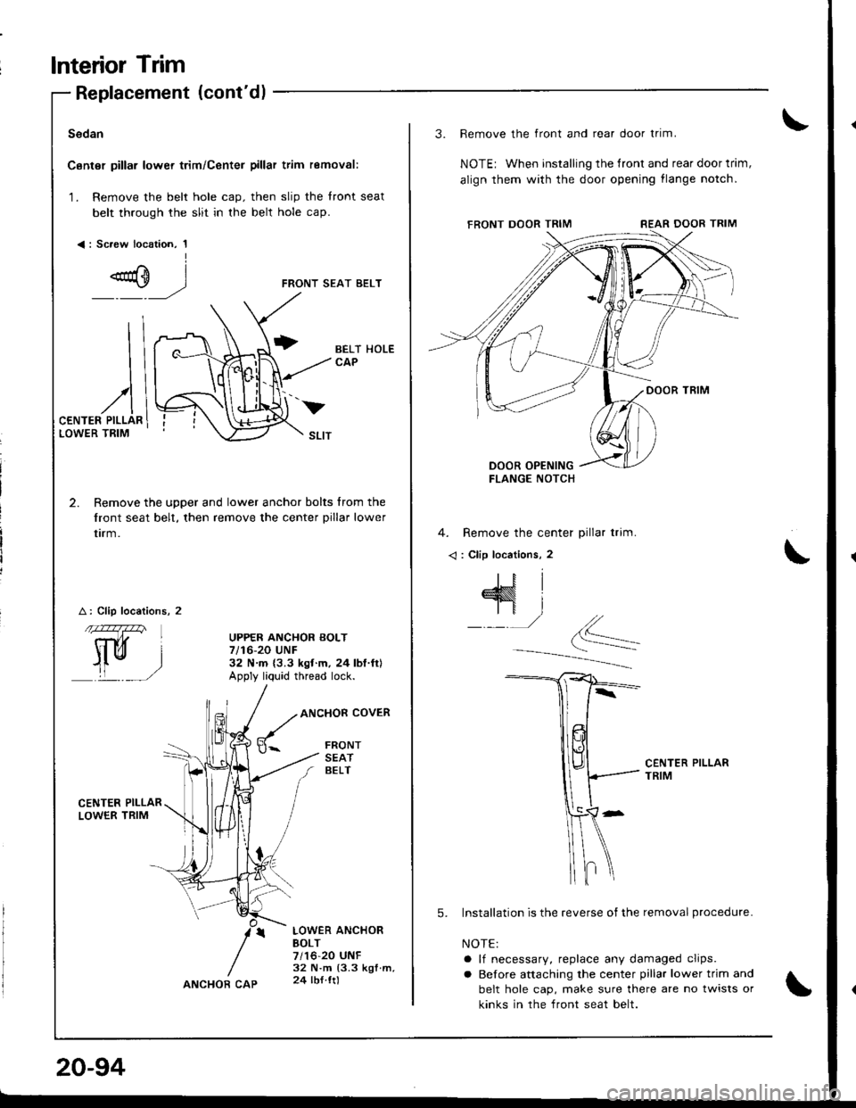
Canter pillar lower trim/Center pillar trim removal:
1. Remove the belt hole cap. then slip the front seat
belt through the slit in the belt hole cap.
<: Sc.ew location, 1I
FRONT SEAT BELT
2. Remove the upper and lower anchor bolts from the
front seat belt, then remove the center pillar lower
trrm.
A: Clip locations, 2
CENTER PII-LARLOWER TRIM
BELT HOLECAP
UPPER ANCHOR BOLT7/16-20 UNF32 N.m {3.3 ksf.m. 24lbl.ft}Apply liq'rid thread lock.
ANCHOR COVER
FRONTSEATBELT
LOWER ANCHOBBOLT7/16-20 UNF32 N.m (3.3 kgf.m,24 lbl ttl
v
20-94
ANCHOR CAP
3. Remove the front and rear door trim.
NOTEr When installing the tront and rear door trim,
align them with the door opening flange notch,
4. Remove the center pillar trim.
< : Clip locations, 2
CENTER PILLARTRIM
5. Installation is the reverse of the removal procedure.
NOTE:
a lf necessary, replace any damaged clips.
a Before attaching the center pillar lower trim and
belt hole cap, make sure there are no twists or
kinks in the front seat belt.
Page 910 of 1681
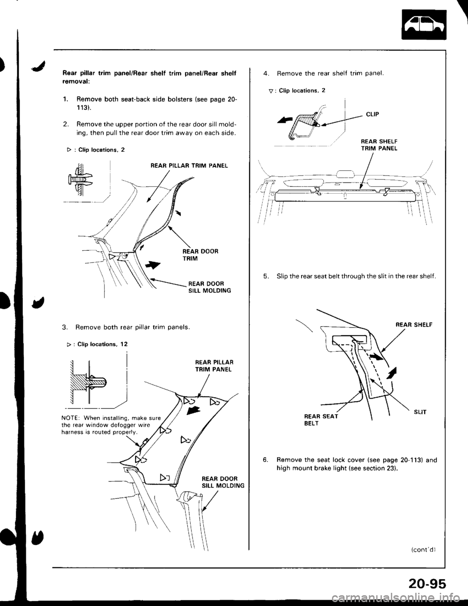
Rear pillar trim panel/Rsar shelf trim panel/Real shelt
removal:
1. Remove both seat-back side bolsters {see page 20-
113).
2. Remove the upper portion of the rear door sill mold-
ing, then pull the rear door trim away on each side.
> : Clip locations, 2
REAR PILLAR TRIM PANEL
SII-I MOLDING
3. Remove both rear pillar trim panels.
> | Clip locations, 12
NOTE: When installing, make surethe rear window defogger wireharness is routed properly.
1
I
,
4. Remove the rear shell trim panel.
V: Clip locations, 2
5. Slip the rear seat belt through the slit in the rear shelf.
REAR SHELF
Remove the seat lock cover (see page 20 113) and
high mount brake light (see section 23).
20-95
Page 913 of 1681
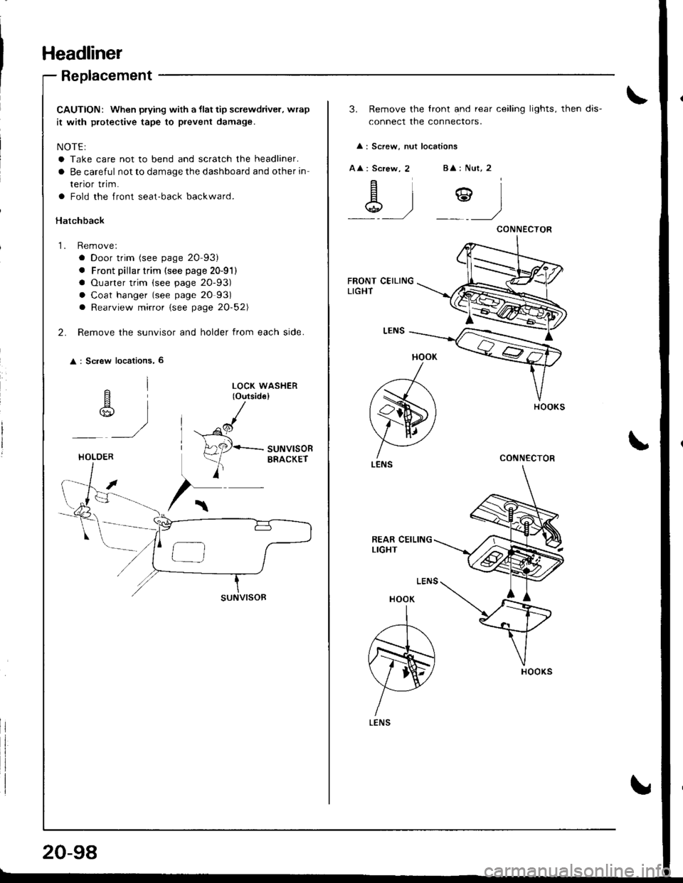
Headliner
Replacement
CAUTION: When prying with a llat tip screwdriver. wrap
it with protective tape to prevent damage.
NOTE:
a Take care not to bend and scratch the headliner.
a Be careful not to damage the dashboard and other in
renor rr|m.
a Fold the front seat-back backward.
Hatchback
1. Remove:
a Door trim (see page 20-93)
. Front pillar trim (see page 20-91)
a Ouarter trim (see page 20-93)
a Coat hanger (see page 20 93)
a Rearview mirror (see page 20-52\
2. Remove the sunvisor and holder from each side.
: Sc.ew locations, 6
^l
r$,,
)
LOCK WASHER(o{rtsid€}
^cl
H
A2P-suNvlsoR
)
ERACKErHOLOER
20-98
3. Remove the lront and rear ceiling lights, then dis-
connect the connectors.
: Screw, nut locations
A : Screw, 2B : Nut, 2
\g .)Y)
HOOK
)
(s)
V AI ./
LENS
HOOK
A
N)
YLENS
CONNECTOR
CONNECTOR
Page 915 of 1681
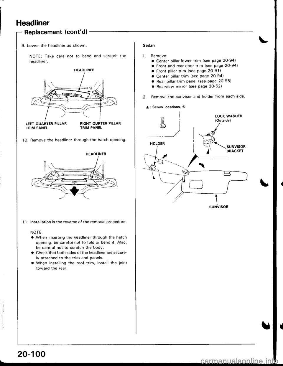
Headliner
Replacement (cont'd)
LEFT OUARTER PILLARTRIM PANEL
9. Lower the headliner as shown.
NOTE: Take care not to bend and scratch the
head liner.
RIGHT OURTER PILLARTRIM PANEL
1O. Remove the headliner through the hatch opening
1 1. Installation is the reverse of the removal procedure.
NOTE:
a When inserting the headliner through the hatch
opening, be careful not to lold or bend it. Also,
be careful not to scratch the body.
a Check that both sides o{ the headliner are secure'
ly attached to the trim and panels.
a When installing the rool trim, install the ioint
toward the rear.
HEAOLINER
HEADLINER
20-100
Sedan
1.Rem ove:
a Center pillar lower trim {see page 20-94)
a Front and rear door trim (see page 20-94)
a Front pillar trim lsee page 20 9'.
a Center pillar trim {see page 20 94)
a Rear pillar trim panel (see page 20-95)
a Rearview mirror (see page 20 52)
Remove the sunvisor and holder from each side.
: Screw locations, 6
elA]*)
HOLDER
suNVlsoR
LOCK WASHER
lOutside)
,al
(
Page 918 of 1681
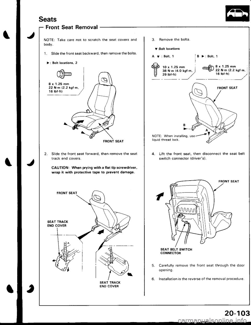
Seats
FrontSeatRemcival
NOTE: Take care not to scratch the seat covers and
oooy.
1 . Slide the front seat backward, then remove the bolts.
>: Bolt locations, 2
3. Remove the bolts.
v:Bolt locations
A V: Bolt, 1I >:Bolr, 1
10 x 1.25 mm l38 N.m (4.0 kgJ m, J,":: J
8 x 1.25 mm22 N.m {2.2 kgt m,
:u",: -/
8 x 1.25 mm I22 N'm 12.2 kst m. )16 rbf.rt)_ /
NOTE: When installing, usey'
--RONT SEAT
2. Slide the front seat forward, then remove the seat
track end covers.
CAUTION: When p.ying with I llat tip screwdliver,
wrap it with protective tape to prevent damage.
liq0id thread lock.
Lift the lront seat, then disconnect the seat
switch connector {driver's).
belt
SEAT TRACKENO COVER
SEAT BELT SWITCHCONNECTOR
5. Carelully remove the front seat through the door
opening.
6. Installation is the reverse of the removal procedure.
Page 926 of 1681
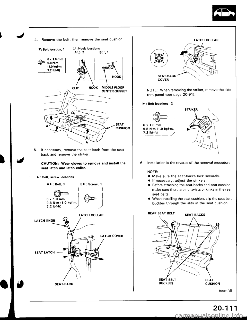
4. Remove the bolt,
V: Boh location, 1
6x1.0mm9.8 N.m11.0 kgf.m.7.2 tbf.ftl
>: Bolt, sc.ew locations
A>: Bolt, 2
CUSHION
5. lf necessary, remove the seat latch from the seat-
back and remove the striker.
CAUTION: Weai gloves to remove and install the
seat latch and latch collal.
-"":=s
then remove the seat cushron.
(-j : Hook loc.tionsai.),2Bl:-r, 1
MIDDLE FLOORCENTER GUSSET
T
)
B>: Screw, 1
j
I
ffipb I
)
LATCH COLLAR
LATCH
SEAT LATCH
LATCH COVER
/
T.BACK
LATCH COLLAR
SEAT BACKCOVER
NOTE: When removing the striker, remove the side
trim panel (see page 2O-91).
> : Bolt locations, 2
InStallation is the reverse ot the removal procedure.
NOTEI
a Make sure the seat backs lock securely.
a lf necessary, adjust the strikers.
o Before attaching the seat-backs and seat cushion,
make sure there are no twists or kinks in the rear
seat belts.
a When installing the seat cushion, slip the seat belt
buckles through the slits in the seat cushion.
FEAR SEAT BELT
6.
SEAT BELTBUCKLESSEATCUSHION
(cont'd )
STRIKER
SEAT.EACKS
20-111
Page 927 of 1681
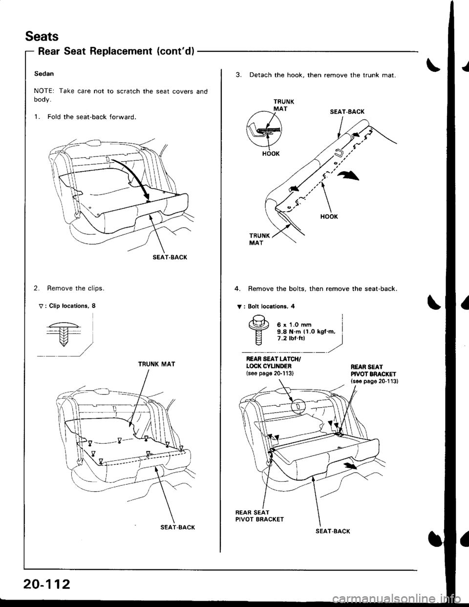
Seats
Rear Seat Replacement {cont'd)
Sedan
NOTE: Take care not to scratch the seat covers and
oooy.
1. Fold the seat-back forward.
2. Remove the clips.
V : Clip locations. 8
SEAT-BACK
TRUNI( MAT
SEAT-BACK
20-112
3. Detach the hook. then remove the trunk mat.
TRUNK
/--x'
w
YHOOK
4. Remove the bolts, then remove the seat-back.
V : Bolt locations, 4
REAR SEAT LATCH/LOCK CYUiIDEB(see pog€ 2G113)REAR SEATHVOT BNACKET(s6e page 20-113)
SEAT-BACK
I
(\Jr', 6 x 1.0 mm I-ET- 9.8 N m (1.0 kgl'm, I
E 7.2 tbt.ht Iq7 ,2'/.
SEAT.BACK
Page 928 of 1681
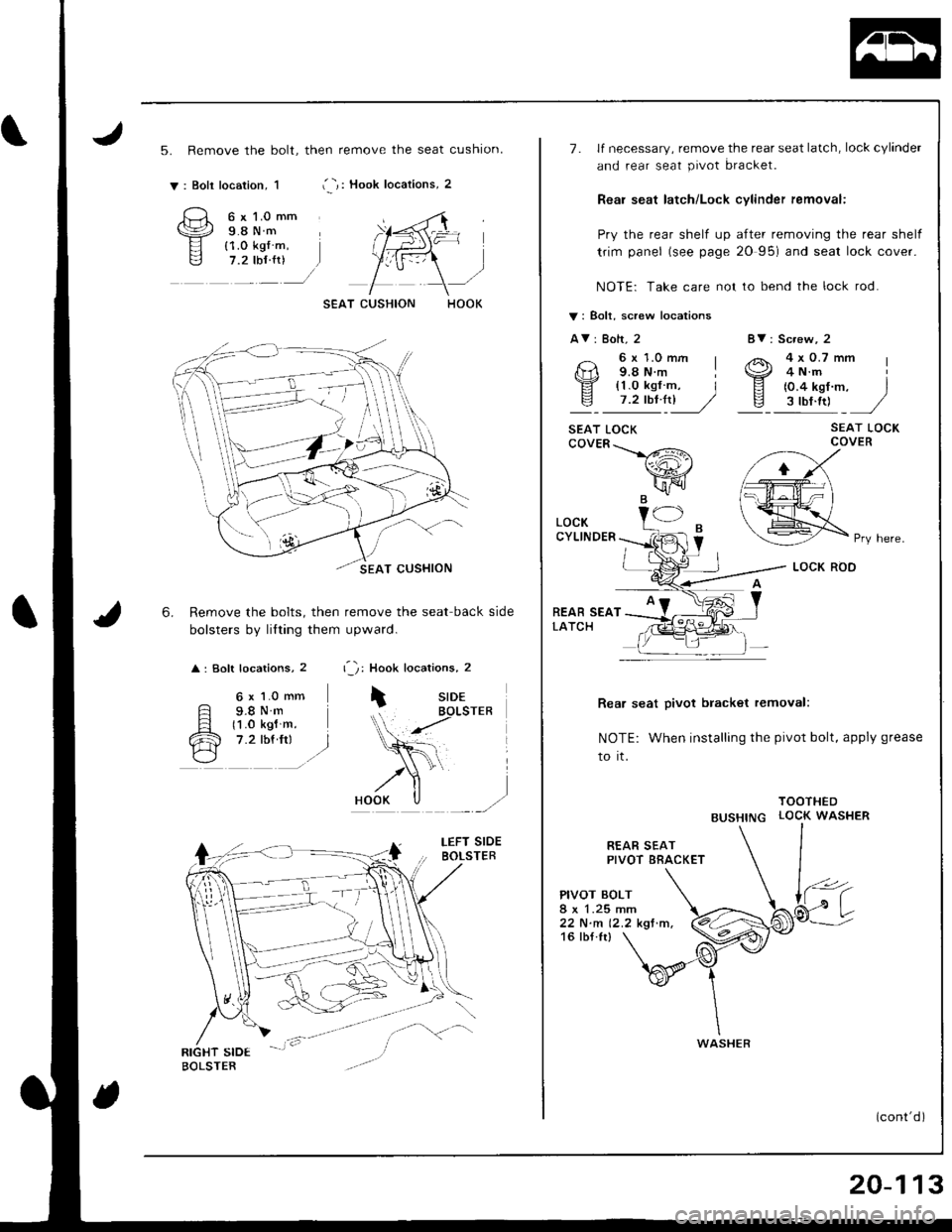
5. Remove the bolt, then remove the seat cushion.
i -,: Hook locations, 2v: Boli location, 1
6.
6 x l.0 mm9.8Nm{1.0 kg{ m,7.2 tbf {r)
6 x 1.0 mm
F s.sN.Fl t1 .o ksl m.
cR 7.2 rbf.frr l./\---l
Remove the bolts, then remove the seat back side
bolsters by lilting them upward.
: Soft locations, 2 r '1: Hook locations, 2
iSIDEBOLSTER
r,1F=
8V: Screw, 2
4x0.7mm4 N.m
{0.4 kgf m, Is ttt.ttl ,/
SEAT LOCKCOVER
Rea, seat pivot bracket removal:
NOTE: When installing the pivot bolt, apply grease
to it.
TOOTHED
BUSHTNG LOCK WASHER
7. lf necessary, remove the rear seat latch, lock cylinder
and rear seat pivot bracket.
Reai seat latch/Lock cylinder femoval:
Pry the rear shelf up after removing the rear shelf
trim panel (see page 20 95) and seal lock cover.
NOTE: Take care not to bend the lock rod.
V: Bolt, screw locations
AV: Bolt, 2
6x1.0mm I9.8 N.m I
!l' {1.0 kgf m, Iv 7.2tbt4l]� //
SEAT LOCKcovER\>#\
wr'\[FIJB.
REAR SEATPIVOT BRACKET
PIVOT BOLT
22 N.m 12.2 kgf.m.16 tbf.Ir)
LOCKCYLINDER
REAR SEATLATCH
Pry here.
WASHER
20-113