HONDA INTEGRA 1998 4.G Workshop Manual
Manufacturer: HONDA, Model Year: 1998, Model line: INTEGRA, Model: HONDA INTEGRA 1998 4.GPages: 1681, PDF Size: 54.22 MB
Page 261 of 1681
PGM-FI System
Manifold Absolute Pressure (MAPI Sensor (cont'dl
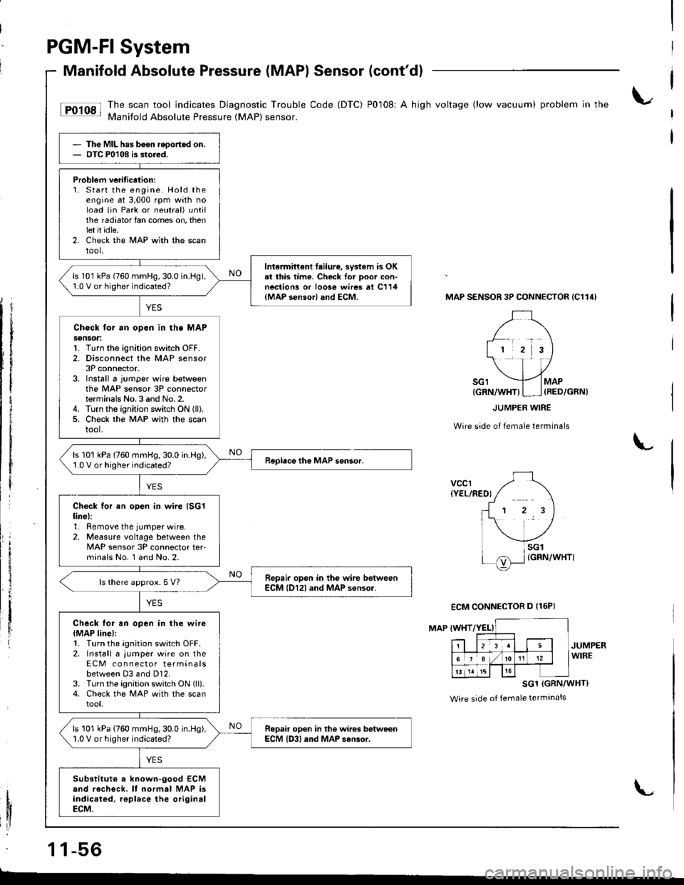
tF'r'sl li:"J:ilfi::il***:ilHi""k:"
code (Drc) P0108' A hish vo*ase (row vacuum) probrem in the
Thc MIL has b6en reoortod on.OTC P0108 is stored.
Problem veritication:1. Start the engine. Hold theengine at 3,000 rpm with noload (in Park or neutral) untilthe radiator fan comes on, thenlet it idle.2. Check the MAP wlth the scantool,
Intermittent f.ilure, svstem is OKal this time. Check lor Door con-nections or loose wires at C114{MAP sensor} and ECM.
ls 101 kPa (760 mmHg,30.0 in.l-lg),1.0 V or higher indicated?
Chock tor an opcn in th. MAPs€nsoa:1. Turn the ignition switch OFF.2. Disconnect the MAP sensor3P connector.3. Install 6 jumper wire betweenthe MAP sensor 3P connectorterminals No.3 and No.2.4. Turn the ignition switch ON (ll).
5. Ch€ck the MAP with the scantool.
ls 101 kPa (760 mmHg,30.0 in.Hg),1.0 V or higher indicated?
Check tor an open in wire (SG1
linel:1. Remove the jumper wire.2, Measure voltage between theMAP sensor 3P connector teFminals No. I and No.2.
Repair open in the wire betweenECM l012l and MAP s€nsor.ls there approx.5 V?
Check for an open in the wire{MAP line):1. Turn the ignition switch OFF.2. Install a jumper wire on theECM co n nector terminalsbetween D3 and Dl2.3. Turn the ignition switch ON lll).4. Check the MAP with the scantool,
ls 101 kPa (760 mmHg,30.0 in.Hg),1.0 V or higher indicated?Repair open in the wires betweenECM {D3, and MAP s6Gor.
Substitut€ a known-good ECMand recheck. It normal MAP isindicaied, rgplace the originalECM.
MAP SENSOR 3P CONNECTOR {C114}
Wire side of female terminals
L
vccr{YEL/RED)
MAP IWHT
JUMPERWIRE
SG1 (GRN/WHT}
Wire side of female terminals
1 1-56
{GRN/WHT)I ] {RED/GRN)
ECM CONNECTOR D {16P}
L
Page 262 of 1681
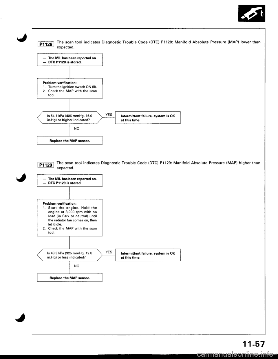
The scan tool indicates Diagnostic Trouble Code (DTC) P1128: Manifold Absolute Pressure (MAP) lower rhan
expected.
The scan tool indicates Diagnostic Trouble Code (DTC) P1129: Manifold Absolute Pressure (MAP) higher than
expected.
- Th€ MIL has b€en reoortod on.- DTC Pl128 is stored.
Problem vorification:1. Turn the ignition switch ON {ll}.2. Check the MAP with the scantool,
ls 54.1 kPa (406 mmHg, 16.0in.Hg) or higher indicated?Intermittent laihre, system i3 OKat this time.
- The MIL has been reooned on.- DTC P1129 is stored.
Problem verification:1. Start the engine. Hold theengine at 3,000 rpm with noload (in Park or neutral) untilthe radiator fan comes on, thenlet it idle.2. Check the MAP with the scantool.
ls 43.3 kPa (325 mmHg, 12.8in.Hg) or less indicated?Intermittoni lailure.3ystem is OKat this time.
11-57
Page 263 of 1681
PGM-FI System
Intake Air Temperatute (lATl Sensor
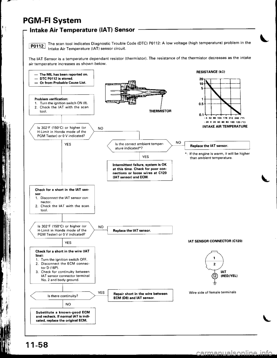
The scan tool indicates Diagnostic Trouble Code (DTC) P0112: A low voltage (high temperature) problem in the
lntake Air Temperature (lAT) sensor circuit.
The IAT Sensor is a temperature dependant resistor (thermistor). The resistance of the thermistor decreases as the intake
air temperature increases as shown below.
RESISTANCE IKO)
THERMISTOR
l1\
\'/
rb lllo,'.u
I
1r3 2r2 2.a l.Flm roo r20 toc)
INTAKE AIR TEMPERATURE
lf the engine is warm, it will be higherthan ambient temperature.
IAT SENSOR CONNECTOR ICl2OI
- The MIL h.s b€an rooorted on.- DTC P0112 is stored.- Or lrom Probable Cau3e List.
P.oblem v6rificationi1. Turn the ignition switch ON lll).2. Check the IAT wirh the scantool.
ls 302'F (150"C) or higher (or
H Limit in Honda mode o{ thePGM Tester) or 0 V indicated?
ls the correct ambient temPerature indicated*?Roolace the IAT sensor.
Into.mittent feilur6, aystem h OKat this timc. Check to. Doot con-nections or loose wires at Cl20{lAT sensor) snd ECM.
Check tor a 3hort in the IAT sen-
1. Disconnect the IAT sensor con
2. Check the IAT with the scantool.
ls 302"F (150'C) or higher (or
H Limit in Honda mode of thePGM Tester) or 0 V indicated?Reolace the IAT sonsor.
Check for a short in the wire (lAT
line):1. Turn the ignition switch OFF.2. Disconnect the ECM connec-tor D (16P).
3. Check for continuity betweenIAT sensor connector terminalNo.2 and body ground.
Rooair short in the wirc botwoenECM {D8) .nd IAT sen3or.ls there continuity?
Substitut€ s known-good ECMand rccheck. lI normal IAT is indi-cated, replace the originel ECM.
1 1-58
Wire side of lemale terminals
L
Page 264 of 1681
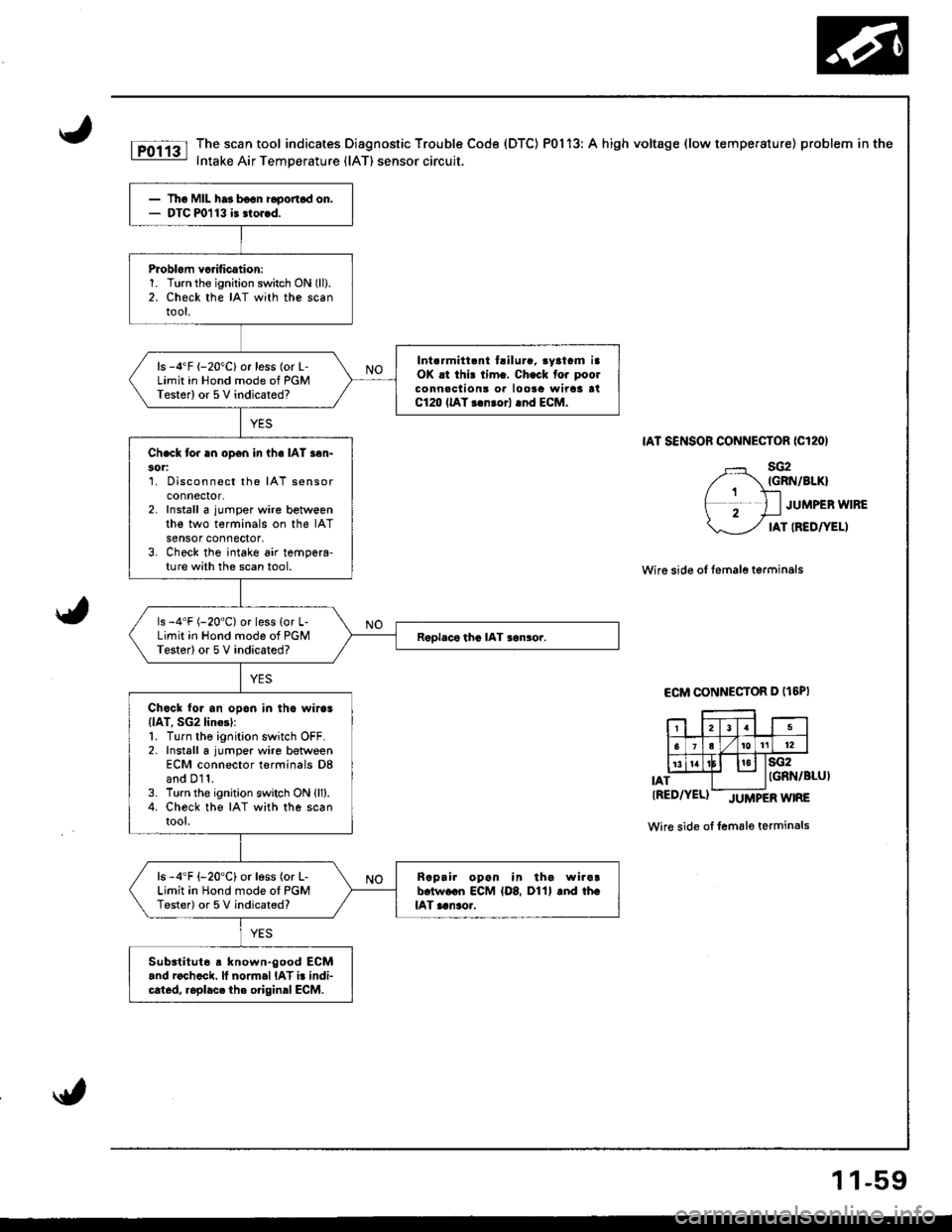
The scan tool indicates Diagnostic Trouble Code (DTC) P0113: A high voltage (low temperature) problem in the
Intake Air Temperature (lAT) sensor circuit.
IAT SENSOR CONNECTOR ICl2OI
sG2IGRN/BIKI
JUMPEB WIRE
IAT IREDTYELI
Wire side of temale terminals
ECM CONNECTOR D (t6PI
IAT
sG2IGRN/BLUI
tRED/YEL)-JUtvtPERWTRE
Wire side of female terminals
Tho MIL ha3 b€on i6ponod on.DTC m113 i3 3lor.d.
Problom vcrification:1. Turn the ignition switch ON (ll).
2. Check the IAT with the scantool.
Int.rmitt.nt t.ilura. .yatrm iaOK .t thi! tim.. Ch.ck fo. poolconnaclion3 or loota wirca atC120 llAT r.nrorl .nd ECM.
ls -4"F {-20"C}or less (or L-Limit in Hond mode of PGMTester) or 5V indicated?
Ch.ck tor an open in ihe IAT s6n-30r:1. Disconnect the IAT sensorconnectot,2. Install a jumper wire betweenthe two terminals on the IATsensor connector,3. Check the intake air tempera-ture with the scan tool.
ls -4'F (-20"C) or less {or L-Limit in Hond mode of PGMTester) or 5 V indicated?
Chock to. an opon in thc wiros(lAT, SG2 lin6l:1. Turn the ignition switch OFF.2. Install a jumper wire betweenECM connector terminals D8and D11.3. Turn the ignition switch ON lll).4. Check the IAT with the scantool.
ls -4'F {-20'C} or less (or L-Limit in Hond mode ot PGMTester) or 5 V indicated?
Raprir opan in tha wira!b.tw.cn ECM {D8, D11} and th.lAT aanao.,
Subatitut6 a known.good ECM.nd roch.ck. ll normal IAT i. indi-cated, roplacc the o.iginal ECM.
1 1-59
Page 265 of 1681
PGM-FI System
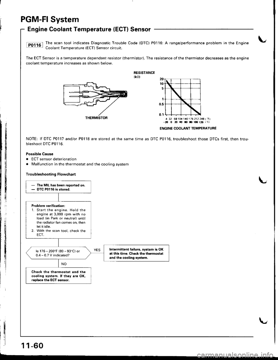
Engine Coolant Temperature (ECTI Sensor
Ip01161 Ihe,scaltool indicates Diagnostic Trouble Code (DTC) P0116: A range/performance problem in the Engine: Coolant Temperature {ECT) Sensor circuit.
The ECT Sensor is a temperature dependant resistor (thermistor). The resistance of the thermistor decreases as the engine
coolant temperature increases as shown below.
RESISTANCEtkol
! 32 68 104 140 i 76 212 248 { "F)-20 o 20 'ra, qt Il rd' t20 r'c)
ENGINE COOLANT TEMP€RATURE
P01 16, troubleshoot those DTCS first, then trou-NOTE: lf DTC P0117 andlo( Po'l'18 are stored at the same time as DTC
bleshoot DTC P0'l16.
Possible Cause
. ECT sensor deterioration
. Malfunction in the thermostat and the cooling system
lroubleshooting Flowchart
I
1 1-60
THERMISTOR
- Th€ MIL has been reoorted on.- DTC P0116 is stored.
Problem veritication:1. Start lhe engine. Hold theengine at 3,000 rpm with noload (in Park or neutrall untilthe radiatorlan comes on, thenlet it idle.2. With the scan tool, check theECT,
Inlermittent failure, system is OKat this time. Chock tho thermostaland th€ cooling syst6m.
ls 176 - 200"F (80 - 93'C) or0.4-0.TVindicated?
Check the thermostat and thecooling system. It th€y ara OK,reolace the ECT sensor,
Page 266 of 1681
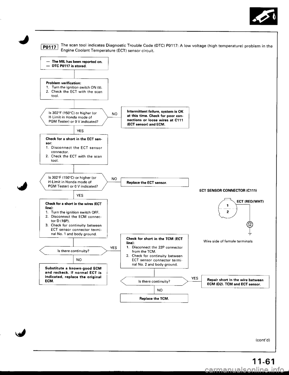
The MIL has b€en reoorted on.DTC P0117 is stored.
Problem verification:1. Turn the ignition switch ON (ll).2. Check the ECT with the scantool.
Intermittent failure, system is OKat this time. Check for poor con-nections or looso wires at C111(ECT sensorl and ECM.
ls 302'F (150'C) or higher {orH Limit in Honda mode ofPGM Tester) or 0 V indicated?
Check tor a short in tho ECT sen-sor:1. Disconnect the ECT sensor
2. Check the ECT with the scantool.
ls 302'F (150'Ci or higher (orH-Limit in Honda mode olPGM Tester) or 0 V indicated?
Check tor s short in the wires (ECTline):r. r urn Ine rgnrtron swttch uFf,2. Disconnect the ECM connector D (16P).
3. Check lor continuity betweenECT sensor connector termi,nal No. 1 and body ground.
Check tor short in the TCM IECTlinell1, Disconnect the 22P connectorfrom the TCM.2. Check for continuity betweenECT sensor connector terminal No- 2 and body ground.
ls there continuity?
Repair shon in the wire botweenECM lD2). TCM and ECT sensor.
iT,011tl The.scan tool indicates Diagnostic Trouble Code (DTC) P0117:Alowvoltage(hightemperature) probleminthe- Engine Coolant Temperature (ECT) sensor circuit.
ECT SENSOR CONNECTOR IC111}
Wire side of fem6le terminals
Substitute a known-good ECMand recheck. lI normal ECT isindicated, replaco the origindlECM.
(cont'd)
NO
11-61
Page 267 of 1681
\
r
I
Ir
PGM.FI
Engine
System
Coolant Temperature (ECTI Sensor (cont'dl
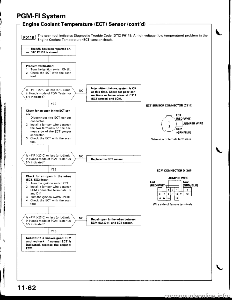
lTo1ig I The.scan tool indicates Diagnostic Trouble Code (DTC) P01 18: A high voltage (low temperature) problem in the.- Engine Coolant Temperature (ECT) sensorcircuit.
ECT SENSOR CONNECTOR (C111)
L
li
li
tllll
tl
fl
ECT{RED/WHT)
sG2{GRN/BLKI
JUMPER WIRE
Wire side o{ lemale terminals
ECM CONNECTOR D {16PI
ECT{RED/WHT)
The MIL has been repo.ted on.DTC P0118 is stor€d.
Problem v€riticetion:1. Turn the ignition switch ON (ll).
2. Check the ECT with the scantool.
Intermittont failure, svstom i3 OKat this time. Check for poor con-noctions or looso wires at C111{ECT sensorl and ECM.
ls -4'F (-20"C) or less (or L-Limitin Honda mode of PGM Tester) or5 V indicated?
Chock tor an opon in the ECT s6n-sor:t. utsconnect tne EL I sensor
2. Install a jumper wire betweenthe two terminals on the harness side of the ECT sensor
3. Check the ECT with the scantool,
ls -4'F (-20"C) or less (or L-Limitin Honda mode of PGM Tested or5 V indicated?
Ch6ck Ior an open in the wiresIECT, SG2lines):1. Turn the ignition switch OFF.2. Install a jumper wire betweenECM conneclor terminals D2and D11.3. Turn the ignition switch ON (ll).4. Check the ECT with the scantool.
ls -4'F {-20'C) or less (or L-Limitin Honda mode ol PGM Tester) or5 V indicated?
Ropair op6n in the wires betwo€nECM lD2, D11) and ECT 3eBor.
Substitute a known-good ECMand recheck. lf normal ECT isindicated, replace the originalECM.
JUMPER WIRE
sG2
r-zlr r5
5e I/ 101t't2
l5
Wire side of female terminals
L
Page 268 of 1681
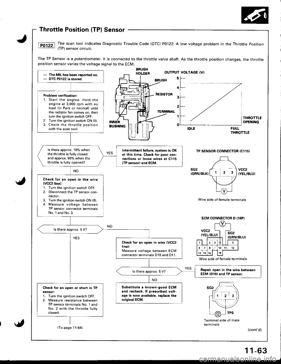
The scan tool indicates Diagnostic Trouble Code (DTC) P0122: A low voltage problem in the Throttle Position{TP) sensor circuil.
The TP Sensor is a potentiometer. lt is connected to the throttle valve shaft. As the throttle position changes, the throttleposition sensor varies the voltage signalto the ECM.
ARUSHHOI.DER
BRUSH 5
FULLTHROTTLE
TP SENSOR CONNECTOR IC115)
Wire side of temale terminals
ECM CONNECTOR D {16P)
(GRN/BLUI
Wire side ot female terminals
sG2 / -\
fr rrr r 'tr\
- 1 2 3)
|{- f- /
| _-,/tlI /6 I TPS-\j/
Terminalside of maletermrnats(To page 11-64)
The MIL has be€n reDort€d on.DTC P0122 is stor€d.
Problem veritication:1. Start the engine. Hold theengine at 3,000 rpm with noload (in Park or neutral) untilthe radiator fan comes on, thenturn the ignition switch OFF.2. Turn the ignition switch ON (ll).
3. Check the throttle positionwith the scan tool.
ls there approx. 10% whenthe throttle is fully closedand approx.90o/o when thethrottle is fully opened?
lntermittenl tailure, system is OKat this time. Check tor poor con-nections or loose wires at Cl15{TP s€nsor) end ECM.
Check lor an open in ihe wire(VCC2line):
1. Turn the ignition switch OFF.2. Disconnect the TP sensor con,nector,3. Turn the ignition switch ON (ll).4. Measure voltage betweenTP sensor connector terminalsNo. l and No. 3.
ls there approx. 5 V7
Check fo. an open in wire IVCC2line):lleasure voltage between ECMconnector terminals D10 and D11.
R.p.ir opon in tho wire betwoenECM {D101 and TP sen3or.ls there approx. 5 V?
Substitute a known-good ECMand recheck. lf pr6sc.ibed volt-age ia now available, replaco theoriginalECM.
Check for an open or 3hort in TP3ensor:1. Turn the ignition switch OFF.2. Measure resistance betweenTP sensor terminals No. '1 andNo.2 with the throttle fullyctoseo,
OUTPUT VOLTAGE {V)
4
RESISTOR3
2
TERMINAL
I
o
THROTTLEOPEI{INGBUS}IINGIDLE
sG2{GRN/BLK)vcc2IYEL/BLU}
vcc2{YEL/BI
l\e
4E
i2iRN,
. llLI5
6/101t 12
t515
(cont'd)
Page 269 of 1681
I
PGM-FI System
Terminal side ot male terminals
ECM CONNECTOR D {16P}
TPSIREO/BLK)tr:l
sG2
rlzlr rl
6,?1otl12
13 tat5l5
{GRN/BLU)
Wire side of female terminals
L
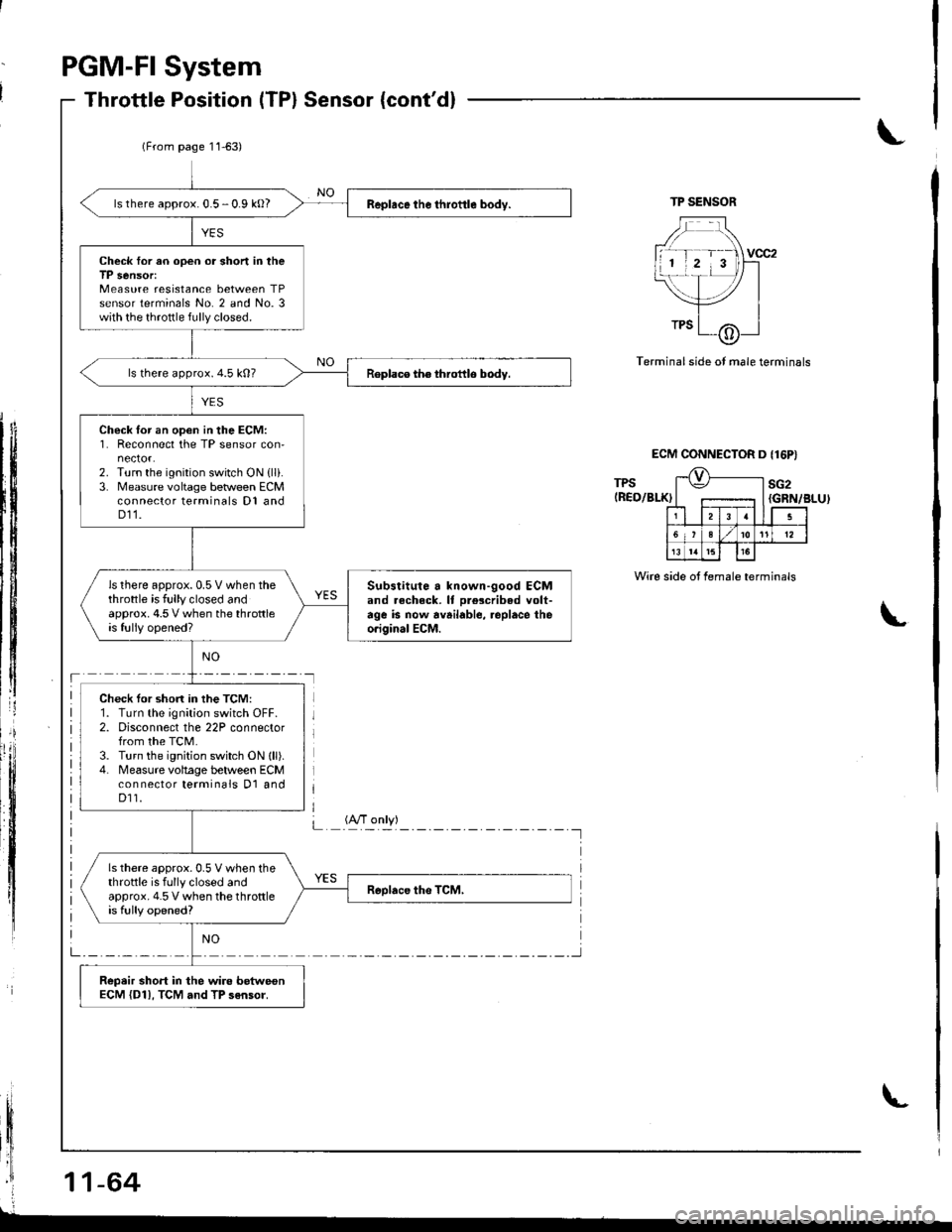
ls there approx. 0.5 - 0.9 kO?
Check Ior an open or short in theTP sensor:Measure resistance between TPsensor terminals No. 2 and No. 3with the throttle fully closed.
ls there approx.4.5 k0?
Check lor an open in the ECM:1. Reconnect the TP sensor con-nector.2. Turn the ignition switch ON {lli.3. Measure voltage beween ECMconnector terminals D1 andD11.
ls there approx.0.5V when thethrottle is fully closed andapprox. 4.5 V when the throttleis fully opened?
Substitute a known-good ECMand .echeck. It olescribed volt-age is now available, .oplace theo.iginal ECM.
Check tor shon in the TCM:1. Turn the ignition switch OFF.2. Disconnect the 22P connectorfrom the TCM.3. Turn the ignition switch ON lll).4. Measure voltage between ECMcon nector terminals D1 andD11.
ls there approx.0.5 V when thethrottle is fully closed andapprox. 4.5 V when the throttleis fully opened?
Repeir short in the wire betweonECM {D11, TCM and TP sensor.
(From page 11-63)
(A/T only)L 'A'"fll I
Page 270 of 1681
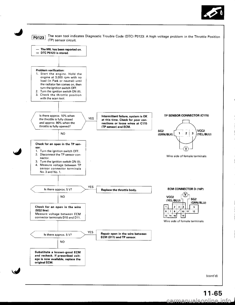
The scan tool indicates Diagnostic Trouble Code (DTC) P0123r A high voltage problem in the Throttle position(TP) sensor circuit,
TP SENSOR CONNECTOR {Cl15I
sG2{GRN/BLK}(YEL/BLU)
Wire side of female terminals
Th€ MIL has been reported on.DTC P0123 is stored.
Problem veriticationl1. Start the engine. Hold theengine at 3,000 rpm whh noload (in Park or neutral) untilthe radiator tan comes on, thenturn the ignition swhch OFF.2. Turn the ignition switch ON (ll).3. Check the throttle positionwith the scan tool.
ls there approx. l0% whenthe throttle is fullyclosedand approx. 90% when thethrottle is fully opened?
Intermittoni {ailure, system is OKal this time. Check tor poor con-nections or loose wires at C115{TP sensor} and ECM.
Check for an open in the TP sen-sot:1. Turn the ignition switch OFF.2. Disconnect the TP sensor con,nectot.3. Turn the ignition switch ON (ll).4. Measure voltage between TPsensor connector terminalsNo.3 and No.'1.
ls there approx. 5 V?
Check for an open in th€ wire(SG2linel:
Measure voltage between ECMconnector terminals Dl0 and 011.
Ropair open in the wir6 betweenECM lD11l and TP sensor.ls there approx. 5 V)
Substitute a known-9ood ECMand rocheck. lf prescribed volt-age is now availablo, roplace theoriginal ECM.
ECM CONNECTOR D I16PI
Wire side of female terminals
(cont'di
1 1-65