HONDA INTEGRA 1998 4.G Workshop Manual
Manufacturer: HONDA, Model Year: 1998, Model line: INTEGRA, Model: HONDA INTEGRA 1998 4.GPages: 1681, PDF Size: 54.22 MB
Page 281 of 1681
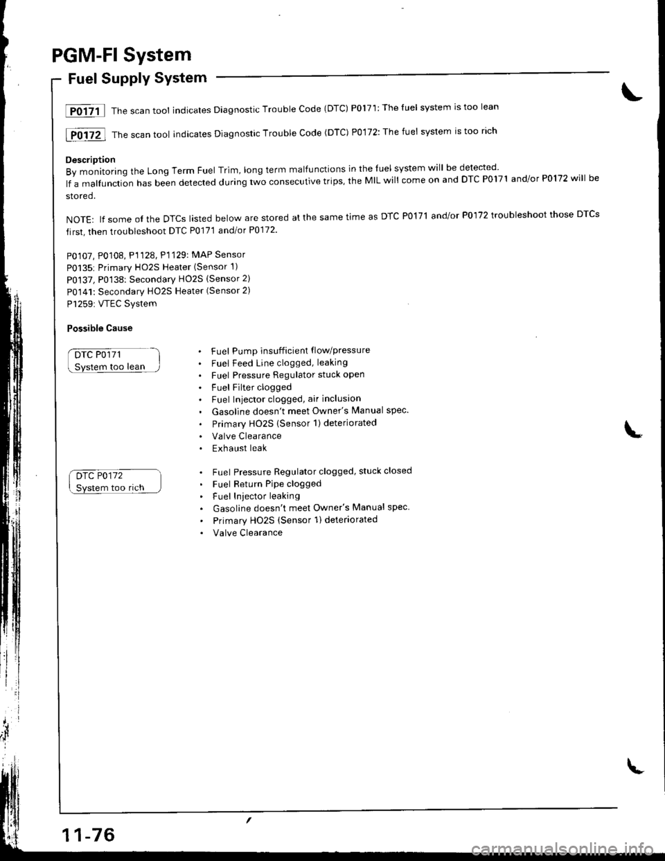
PGM-Fl System
Fuel Supply System
lF0{7il Thescantool indicates Diagnostic Trouble Code (DTC) P0171:Theluel system rstoo lean
[F0i72l Th" ""un tool indicates Diagnosric Trouble code (DTc) p0,172: The fuet system is too rich
Description
By monitoring the Long Term Fuel Trim, long term malfunctions in the luel system will be detected
lf a malfunction has been detected during two consecutive trips, the MIL will come on and DTC P0171 and/or P0172 will be
stored.
NOTE: lf some ol the DTCS lasted below are stored at the same time as DTC PolTl and/or P0172 troubleshoot those DTCS
first, then troubleshoot DTC P0171 andlot P0172
PO107, P0108, P1128. P1129: MAP Sensor
P0135: Primary HO2S Heater (Sensor 1)
P0137, P0138: Secondarv HO2S (Sensor 2)
P0141: Secondary HO2S Heater (Sensor 2)
P1259: VTEC Svstem
Possible Cause
DTC P0171
too lean
Drc P0172
Svstem too rich
. Fuel Pump insufficient flowpressure
. Fuel Feed Line clogged, leaking
. Fuel Pressure Regulator stuck open
. Fuel Filter clogged. Fuel Iniector clogged, air inclusion
. Gasoline doesn't meet Owner's Manual spec.
. Primary HO2S (Sensor 1)deteriorated
. Valve Clearance. Exhaust leak
. Fuel Pressure Regulator clogged, stuck closed
. Fuel Return Pipe clogged
. Fuel Iniector leaking
. Gasoline doesn't meet Owner's Manual spec
' Primary Ho2s (Sensor 1) deteriorated
. Valve Clearance
Page 282 of 1681
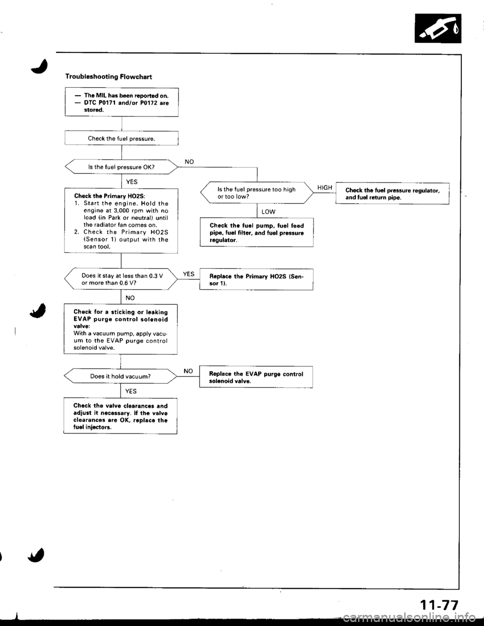
Troubleshooting Flowchart
HIGH
- The MIL ha3 been rcoortod on.- OTC P0171 andlor PO'l72.re3tored.
ls the Iuel pressure OK?
ls the fuel pressure too highChock th€ luel p.essure regulator,and tu€l return pipe.Ch€ck the Primary HO2S:1. Start the engine. Hold theengine at 3,000 rpm with noload (in Park or neutral) untilthe radiator lan comes on.2. Check the Primary HO2S{Sensor 1) output with thescan tool.
Chock the tuel pump, fuel feodpipe, fuol fiher, and tuol prcssureregulator.
Does it stay at less than 0.3 Vor more than 0.6 V?Rapl.ce the Primary HO2S {Sen-3or ll.
Check lor a sticking or l€akingEVAP purge control solenoid
With a vacuum pump, apply vacu,um to the EVAP purge controlsolenoid valve.
Does it hold vacuum?
Chock the valvc cl6a.ance3 andadjust it nocessary. lf th. valvocloarance3 are OK, reDlaco thGtuel ini€cto6.
11-77
Page 283 of 1681
PGM-FI System
Random Misfire
1T0-500 1 a nd Fo-30ittrrousFF0304-lThB scan tool indicates Diagnostic Trouble Code {DTC) P0300 and some of
P0301 - P0304: Random misfire.
Doscription
Misfir; detection is accomplished by monitoring the crankshaft speed with the crankshaft speed fluciuation sensor which
is attached to the crankshsft.
lf misfiring strong enough to damage the catalyst is detected, the MIL will blink during iho time of its occurrence, and DTC
p0300 and some of DTCS p0301 through P0304 will be stor€d. Then, after misfire has ceased, the MIL will come on.
lf misfiring that increases emissions is detected during two consecutive driving cycles, the MIL will come on, and DTC
PO3O0 and some ot DTCS P0301 through P0304 will be stored
NOTE: lJ some of the DTCS listed below are stored at the same time as a misfire DTC, troubleshoot those DTCS first. then
troubleshoot the misfire DTC.
P0171, P0172: Fuel metering
P0505: ldle Control SYstem
P1361, P1362: TDC sensor
P1381. P1382: CYP sensor
P1508: IAC valve
Possible Cause
. Fuel pump insufficient fuel pressure. amount of flow
. Fuel line clogging, blockage, leakage
. Fuel {ilter clogging
a Fuel pressure regulator stuck open
. Distributormallunction
o lgnition coil wire open, leakage
. lgnition control module malfunction
. Valves carbon deposit
a Compression low
. IAC valve malfunction
. Fast idle thermo valve malfunction
o Fuel does not meet Owner's Manual spec., lackotfu€l
. VTEC system malfunction
Troubleshooting
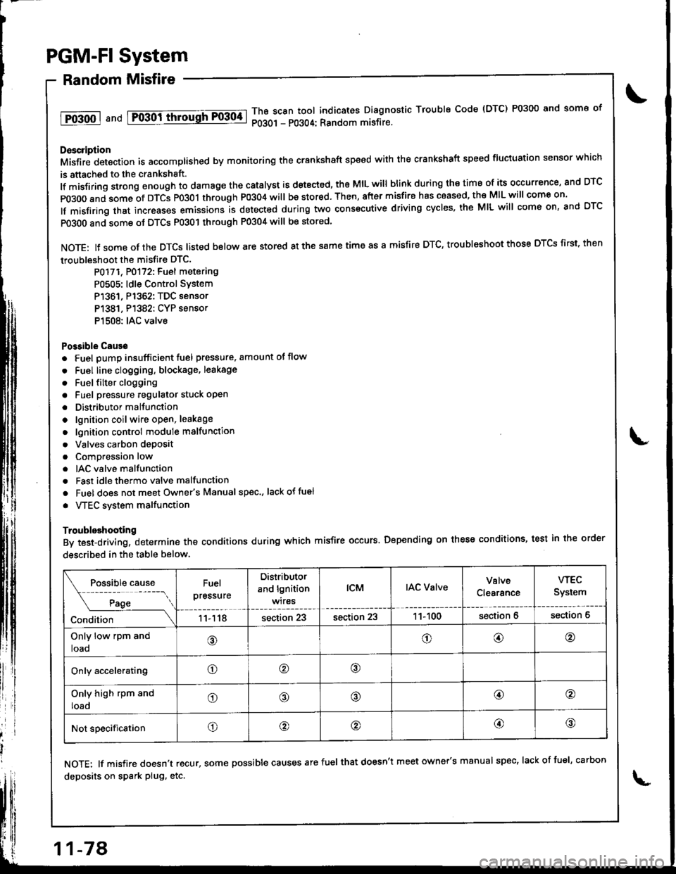
By test-driving, determine the conditions during which misfire occurs. Depending on these conditions, test in the order
described in the table below.
Fuel
pressure
Distributor
and lgnition
wires
tcMIAC ValveValve
Clearance
wEc
System
11118section 23section 231 1- 100section 6section 6
Only low rpm and
loao@o@@
Only acceleratingo@o
Only high rpm and
loado@@@o
Not specificationo@@@@
NOTE: lf misfire doesn't recur, some possible causes arefuel that doesn't meet owner's manual spec, lackoffuel, carbon
deposits on spark plug, etc.
11-78
Page 284 of 1681
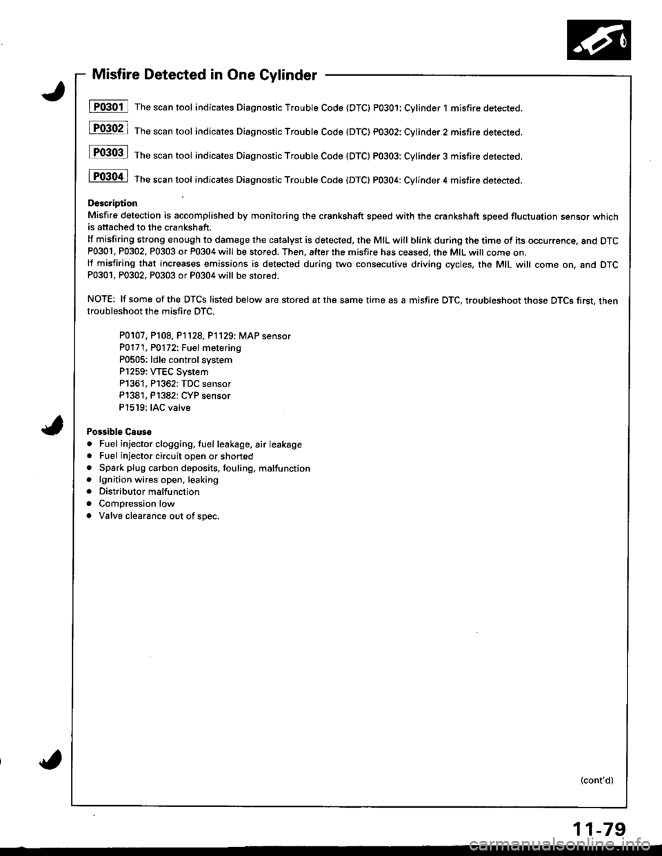
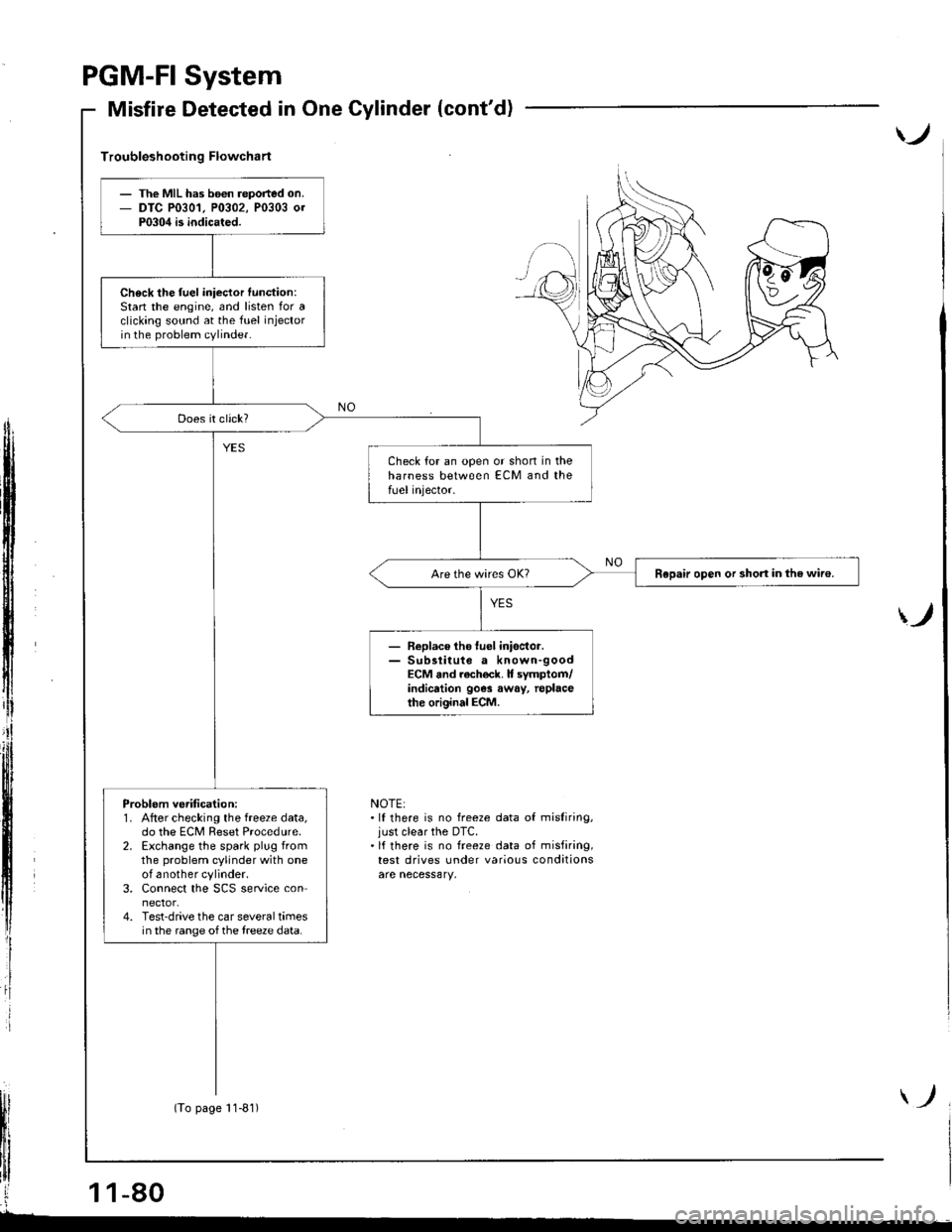
Misfire Detected in One Cylinder
I P0301 The scan tool indicates Diagnostic Trouble Code (DTC) PO3O1:Cylinder 1 misfire detected.
[F03021 1;," """n tool indicares Diagnostic Troubte Code (DTC) pO3O2: Cylinder2 misfire detected.
P0303 | ths sssn tool indicates Diagnostic Trouble Code (DTC) PO3O3: Cylinder3 misfire detected.
i P0304 | tne scan tool indicates Diagnostic Trouble code {DTC} PO3O4: Cylinder 4 misfire detected.
Doscription
Misfire detection is accomplished by monitoring the crsnkshaft speed with the crankshaft speed fluctuation sensor whichis attached to the crankshaft.
lf misfiring strong enough to damage the catalyst is detected, the MIL will blink during the time of its occurrence, and DTCP0301, P0302, P0303 or P0304 will be stored. Then, after the m;sfire has ceased, the MIL witt come on.lf misfiring that increases emissions is detected during two consecutive driving cycles, the MIL will come on, and DTCP0301, P0302, P0303 or P0304 will be stored.
NOTE: lf some of the DTCS listed below are stored at the same time as a misfire DTC, troubleshoot those DTCS first, thentroubleshoot the misfi.e DTC.
P0107, P108, P1128,P'1129:� MAP sensor
PO171, PO172t Fuel metering
P0505; ldle control system
P1259: WEC System
P1361, P1362: TDC sensor
P138'1, P1382: CYP sensor
P1519: IAC valve
Possibls Caus6
. Fuel injector clogging, fuel leakage, air leakage
. Fuel injector circuit open or shoned. Spark plug carbon deposits, fouling, malfunction. lgnition wires open, leaking
. Distributor malfunction
. Compression low
a Valve clearance out of spec.
(cont'd)
11-79
Page 285 of 1681
PGM.FI
Misfire
System
Detected in One Cylinder (cont'd)
)
Troubleshooting Flowchart
ff
i
)
NOTE:.lf there is no freeze data of misliring,just clear the DTC.'lf there is no freeze data of misfiring,test drives under various conditions
The MIL has b6€n reported on.DTC P0301, P0302, P0303 0rP0304 is indicated.
Check the fuel iniector function:Stan the engine, and listen for aclicking sound at the fuel injectorin the problem cylinder.
Check for an open or shon in theharness between ECM and thefUel injector.
Repair open or short in the wiro.
- Replace tho luel inisctor.- Sub3titute a known-goodECM and rach€ck. It symptom/indicrtion 90e3 away, replacethe original ECM.
Problem ve.ification:1. After checking the freeze data,do the ECM Reset Procedure.2. Exchange the spark plug fromthe problem cylinder with oneof another cylinder.3. Connect the SCS service connector.4. Test-drive the car several timesin the range of the treeze data.
(To page 11-81)
Page 286 of 1681
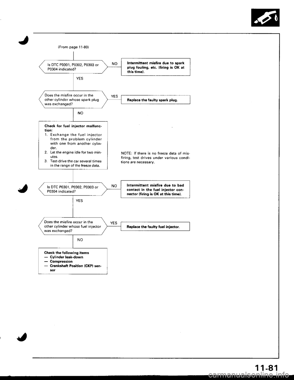
(From page l1-80)
Iniermittenl misfire due lo sparkplug fouling, otc. Iti.ing is OK atthis timo).
Does the misfire occur in theother cylinder whose spark plugwas exchanged?Replace the faultv spark plug.
Check for tuel ini€ctor maltunc-taon:1. Exchange the fuel injectorfrom the problem cylinderwith one from another cylin'der.2. Let the engine idle lortwo min-uteS.3. Test-drive the car sevoraltimesin the range ofthe treeze data.
Int€rmitt€nt mislire due to badcontact in tho tuel iniector con-nector lfiring is OK at thb time).
Does the misfire occur in theother cylinder whose tuel injectorwas exchanged?Replace the laultv tuel iniector.
Check the following items- Cylinde. lerk-down- Compaession- Crankshafl Position (GKPI son-
NOTE: lf there is no freeze data of misfirang, test drives under various condi-trons are necessary.
1 1-81
Page 287 of 1681
I
PGM-FI System
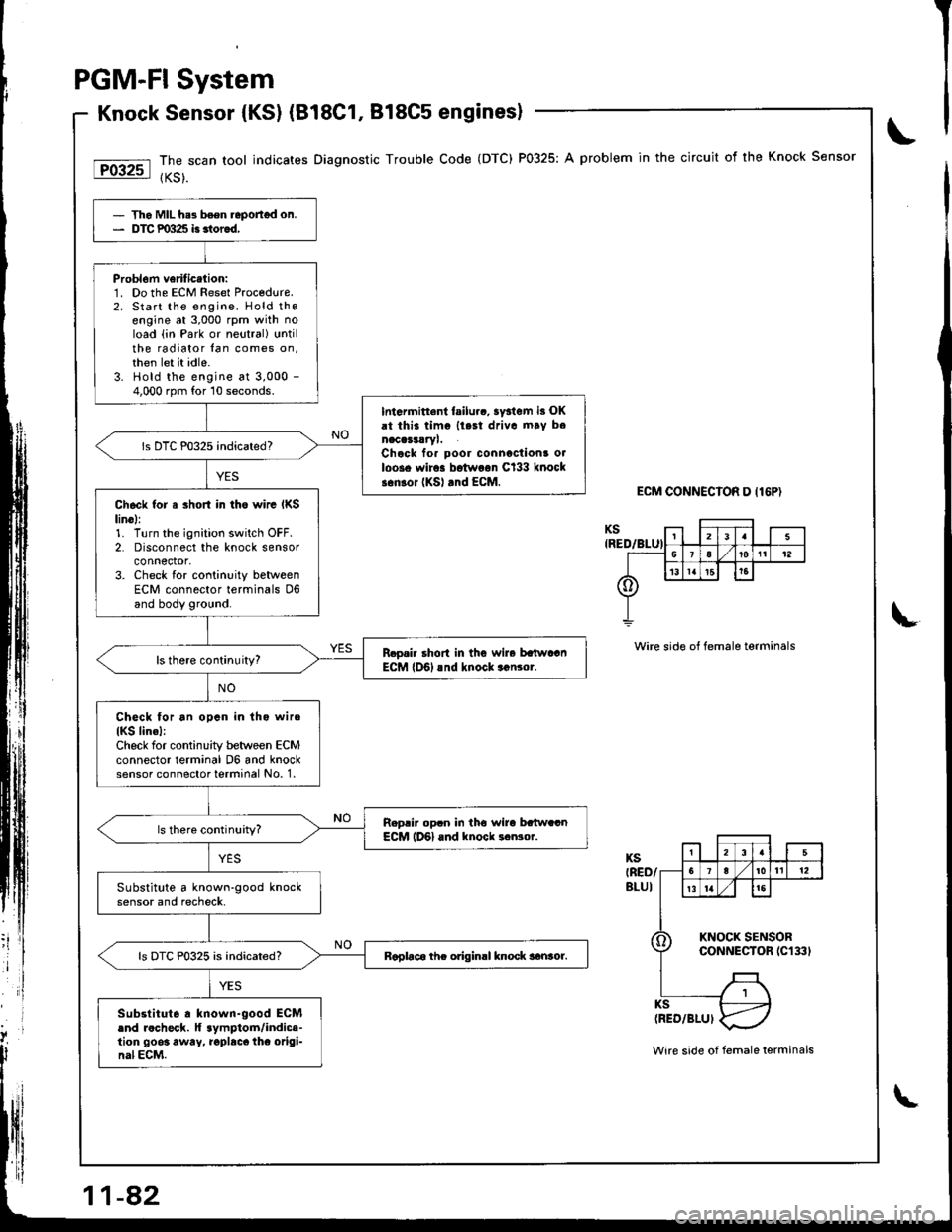
Knock Sensor {KSl (B18C1, 818C5 enginesl
The scan tool indicates Diagnostic Trouble Code (DTC) P0325: A problem in the circuit of the Knock Sensor
{KS).
ECM CONNECIOR D I16P)
Wire side of female terminals
- Tho MIL he3 b6en.eportgd on.- DTC P0325 i3 3tor6d,
Probl6m veriticalion:1. Do the ECM Reset Proc€dure.2. Start the engine. Hold theengine at 3,000 rpm with noload {in Park or neutral} untilthe radiator lan comes on,then let it idle.3. Hold the engine at 3,000 -
4,000 rpm for 10 seconds.
Intarmitt.nl failurc, ay3tem i3 OKrt thii timc llest driva mav b.naccrsrryl.Chcck for poor connactions o.loos. wir.. botw..n Cl33 knocks.nlor (KSl rnd EcM.
Ch6ck {or a 3hort in tho wirc IKSlin6l:1. Turn the ignition switch OFF.2. Disconnect the knock sensorconnector,3. Check for continuity betweenECM connector terminals D6and body ground.
R.o.i. short in thG wire batwaanECM lD6l rnd knock..n3or.
Check for an opcn in lho wiro
IKS lin.l:Check for continuity between ECMconnector terminal D6 and knocksensor connector terminal No. 1.
Reprir op.n in tho wira bttw..nECM lD6l and knock ..Nor.
Substitute a known-good knocksensor and recheck.
Raplac6 thc odginrl knock sanror.ls DTC P0325 is indicated?
Substitut6 . known-good ECM.nd rocheck. lf aymptom/indic.-tion 9003 away, .opbcc thc origi-nal ECM.Wire side of female terminals
Page 288 of 1681
t@
tFffi6l
F136il
l-P1362l
Fi3BTl
tFE82-l
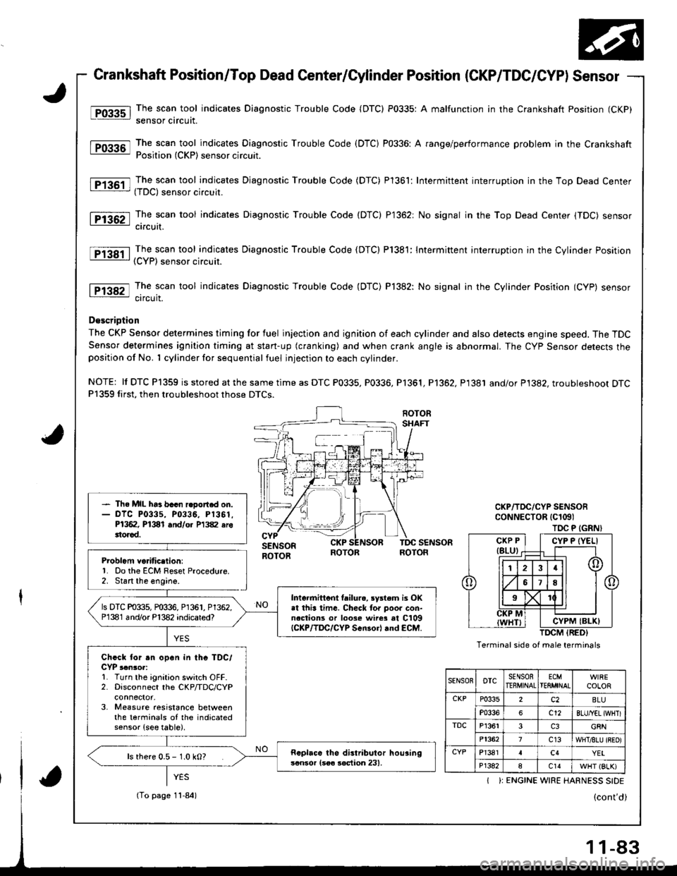
Crankshaft Position/Top Dead Center/Cylinder Position (CKP/TDC/CYPI Sensor
The scan tool indicates Diagnostic Trouble Code {DTC) P0335: A malfunction in the Crankshaft Position (CKP)
sensor circuit.
The scan tool indicates Diagnostic Trouble Code (DTC) P0336: A range/performance problem in the CrankshaftPosition (CKP) sensor circuit.
The scan tool indicates Djagnostic Trouble Code (DTC) Pl361: Intermittent interruption in the Top Dead Center(TDC) sensor circuit.
The scan tool indicates Diagnostic Trouble Code (DTC) P1362: No signal in the Top Dead Center (TDC) sensorcircuit.
The scan tool indicates Diagnostic Trouble Code (DTC) P1381: Intermittent interruption in the Cylinder Position(CYP) sensor circuit.
The scan tool indicates Diagnostic Trouble Code (DTC) P]382: No signal in the Cylinder Position (CYP) sensorcircuit.
D€scription
The CKP Sensor determines timing for fuel injection and ignition of each cylinder and also detects engine speed. The TDCSensor determines ignition timing at stan-up (cranking) and when crank angle is abnormal. The Cyp Sensor detects theposition of No. 1 cylinder for sequential fuel injection to each cylinder.
NOTE: ll DTC P1359 is stored at the same time as DTC P0335, P0336, Pl361, P1362, P1381 and/or P1382. troubleshoot DTCP1359 first, then troubleshoot those DTCS.
Problcm va.itic.lion:'1. Do the ECM Reset Procedure.2. Stan the engine.
- Th. MIL ha3 bacn r.oort.d on.- olc P0335, P0336, P1361.P1362, P1381 and/o. P1382 erottorad.
Intormittcnt tailurc, rystem is OKat this lima. Checl tor poor con-naclions or loose wire3 at C109{CKP/lDC/CYP Scn30rl rnd €CM.
ls DTC P0335, P0336, P1361, P1362.P1381 and/or P'l382 indicared?
Chcck for .n open in thc TDC/CYP ,.n3or:L Turn the ignition switch OFF.2. Disconnect the CKP/TDC/CYP
3, Measure aesistance betweenthe terminals oI the indicatedsensor {see table).
Rcplaca tho distributor hou3ingscnsor {soa soction 231,ls rhere 0.5 - 1.0 kO?
TOC P (GRN}
Termanal side of male terminals
CYP P {YELI
CYPM IBLK)
SENSOnoTcSENSORTEEMINALECMTEflMINALCOLOR
CKPP0335c2BLU
P0336c12BLU/YEL {WHTI
TDCP13613G8N
P13627c13WHT/8LU {BEO)
CYPP13814c4YEI
P1382ac14WHT (BLK)
I ): ENGINE WIRE HARNESS SIDE
(To page 11-84)
-83
Page 289 of 1681
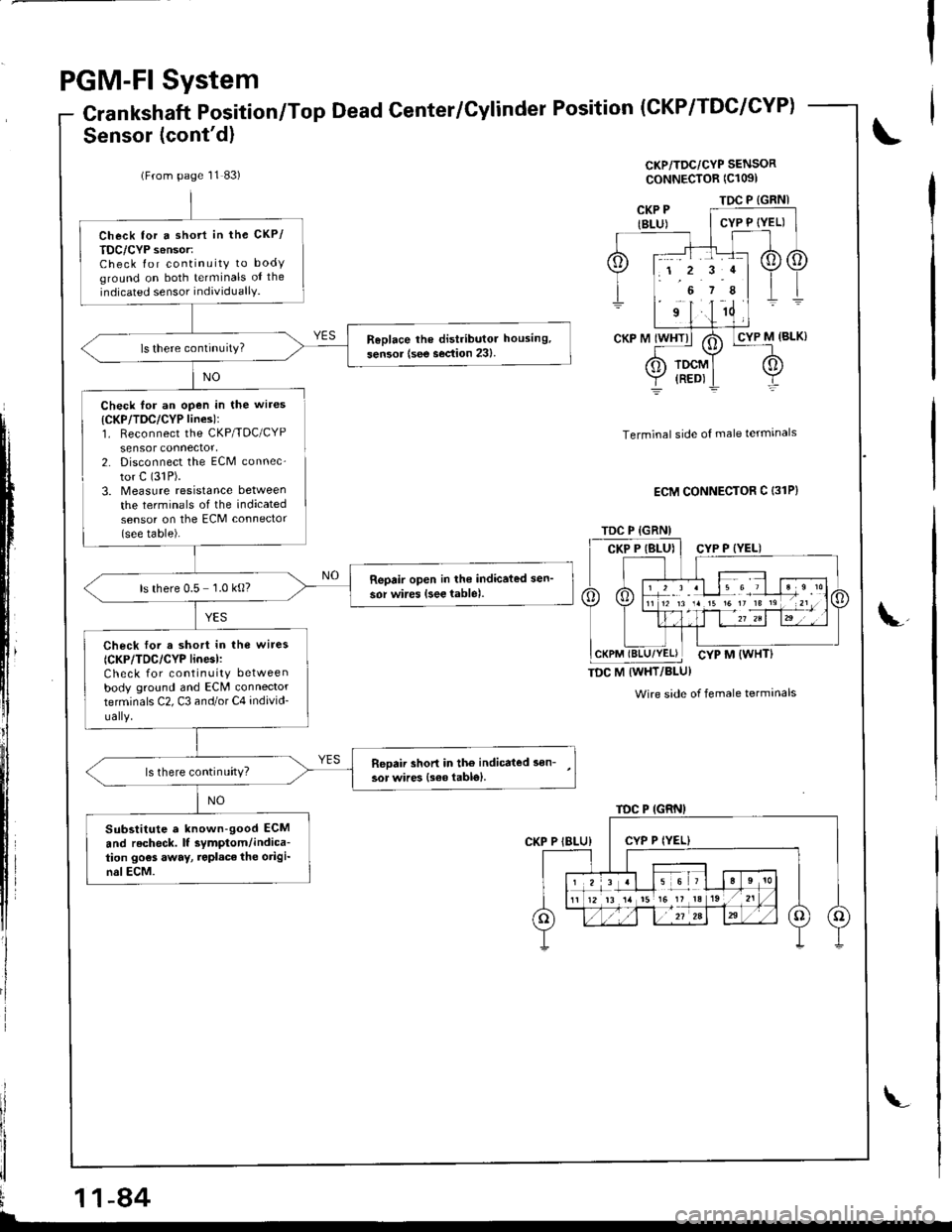
PGM-FI System
Crankshaft Position/Top Dead Center/Cylinder Position
Sensor (cont'd)
(CKP/TDC/CYP)
CKP/TDC/CYP SENSOR
ooNNECTOR (Cl091
NO
il
,ll
I
Check for an open in the wires
{CKP/TDC/CYP lines):1. Reconnect the CKP/TDC/CYPsensor connector,2. Disconnect the ECM connec-
tor C (31P).
3. Measure resrstance between
the terminals of the indicatedsensor on the ECM connector(see table).
Terminal side of male termrnals
ECM CONNECTOR C {31P}
TDC M IWHT/BLU}
Wire side of female terminals
i
ii!\
(From page 11 83)
Check tor a shott in the CKP/
TDC/CYP s6nsor:Check for continuity to bodyground on both terminals oI the
indicated sensor individuallY.
ReDlace lhe distributor housing,
sen3or {see section 23}.
Reoair open in lhe indicated sen'
sor wires {see lable).ls there 0.5 1.0 kg?
Check lor a short in the wire3
{CKP/TDC/CYP linesl:Check for continuity betweenbody ground and ECM connectorterminals C2, C3 and/or C4 individ-
ually.
Reoaii shon in tho indicated son-
3or wires {s€6 table}.ls there continuity?
Substitute a known-good ECM
and recheck. lf symptom/indica-tion go€s away, repl.ce the origi-nslECM.
TDC P {GRNI
TDC P (GRN)
1 2 r .l le 6 7
TDC P {GRN)
1 2 3 al 15 6 ,
12 13 14 t5 16 It 13
11-84
Page 290 of 1681
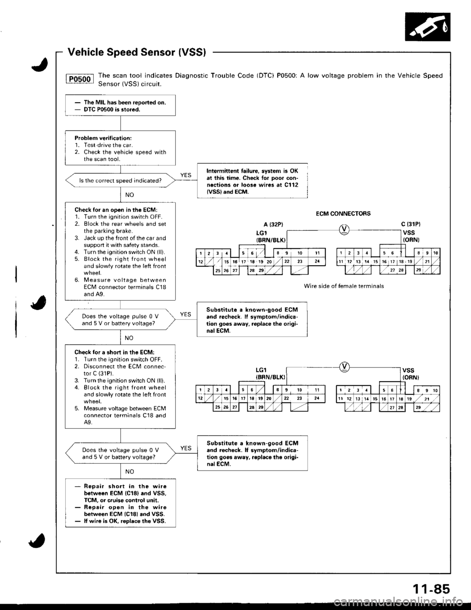
The scan tool indicates Diagnostic Trouble Code (DTC) P0500r A low voltage problem in the Vehicle Speed
Sensor (VSS) circuit.
Intermittent failure, system is OKat this time. Check for ooor con-neciions or loose wires at C112IVSSI and ECM.
ECM CONNECTORS
A (32P)
LGlIBRN/8LK)
c (31Pt
vss{ORN)
Wire side of female terminals
The MIL has been reported on.DTC P0500 is stored.
Probleft veritication:1. Test drive the car.2. Check the vehicle speed withthe scan tool,
ls the correct speed indicated?
Check lor an open in the ECM:1. Turn the ignition switch OFF.2. Block the rear wheels and setthe parking brake.3. Jack up the front of the car andsuppon it with safety stands.4. Turn the ignition switch ON (ll).
5. Block the right front wheeland slowly rotate the left front
6. Measure voltage betweenECM connector terminals C18and A9.
Substitute a known-good ECMand recheck. H symptom/indica-tion goes away, replace tho origi-nalECM.
Does the voltage pulse 0 Vand 5 V or battery voltage?
Check lor a shori in th€ ECM:1. Turn the ignition switch OFF.2. Disconnect the ECM connector C (31P).
3. Turn the ignition switch ON (lli.4. Block the right front wheeland slowly rotate the left front
5. Measure voltage between ECMconnector lerminals C18 andA9.
Substitute a known-good ECMand lecheck. lf symptom/indica-tion goos away. rsplaco the origi-nalECM.
Does the vohage pulse 0 Vand 5 V or battery voltage?
Repair short in the wireb€tween ECM {C18} end VSS,TCM, or cruise control unit.Repeir open in the wirebetween ECM (C18) aod VSS.ff wire is OK, replace the VSS.
ra 17 18 19 20t6 ]t 13r19
LG1{BRN/BLKIvss(ORNI
23563910 1156
12i5r92022 23 2a11 1213 1/tr6ts/zt
25262Aa9,/2724," ,/ ,,:
1 1-85