HONDA INTEGRA 1998 4.G Workshop Manual
Manufacturer: HONDA, Model Year: 1998, Model line: INTEGRA, Model: HONDA INTEGRA 1998 4.GPages: 1681, PDF Size: 54.22 MB
Page 271 of 1681
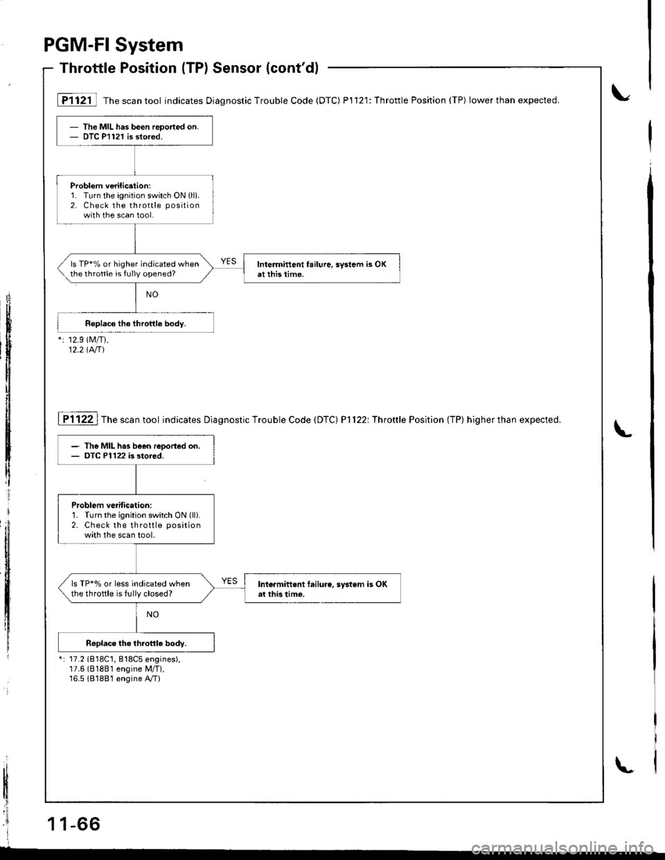
- The MIL has been reported on.- DTC P1121 is stored.
Problem verification:1. Turn the ignition switch ON (lli.
2. Check the throttle position
with the scan tool.
ls TP*% or higher indicated whenthe throttle is fully opened?Inte.mittent failure, sy3lem is OKat this time.
[FTl2il Th"r"untool indicates Diag nostic Trouble Code (DTC) P1121: Throttle Position (TP) lowerthan expected.
": 12.9 (M/Ti,
12.2 tA/T)
I P1122 | The scan tool indicates Diagnostic Trouble Code {DTC) P]122: Throftle Position (TP) higher than expected.
*: 17.2 1818C1, 818C5 engines),17.6 (81881 engine M/T),16.5 (81881 engine A,/T)
- The MIL has been reoorted on.- OTC P1122 is stored.
Problem verification:1. Turn the ignition switch ON (ll).
2. Check the throttle positionw;th the scan tool.
ls TP*% or less indicated whenthe throftle is fully closed?Ini€rmiftent failure, system is OKat thi3 tim6.
PGM-FI System
Throttle Position (TP) Sensor {cont'dl
1 1 1-66
t
\
L
Page 272 of 1681
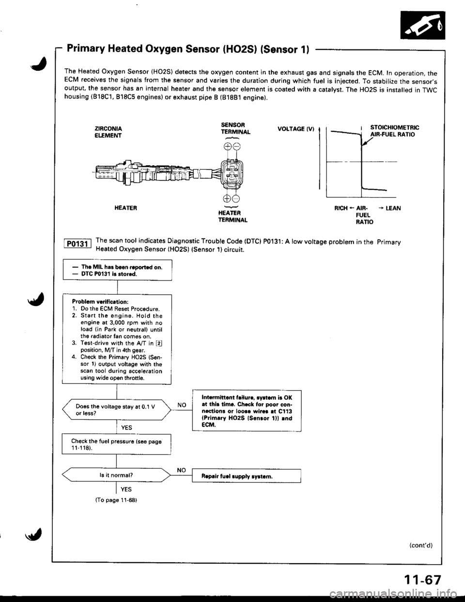
Primary Heated Oxygen Sensor (HO2S) lsensor 1l
The Heated Oxygen Sensor {HO2S) detects the oxygen content in the exhaust gas and signals the ECM. In operation, theECM receives the signals from the sensor and varies the duration during which fuel is iniected. To stabilize the sensor,soutput, the sensor has an internal heater and the sensor element is coated with a catalyst. The HO2S is installed in TWChousing (818C'1, 818C5 engines) or exhaust pipe B {81881 engine).
ztFcoNtAEI."EMEI'IT
SENSORTERMINALVOLTAGE IV)
HEATERIIEATERTERMINAL
RICH. AIR. * LEANFUELRANO
Thescantool indicates Diagnostic Trouble Code IDTCI PO13l: A low voltage problem in the primary
Heated Oxygen Sensor (HO2S) (Sensor 1) circuit.
- Th6 MIL h.r baan.ago.t.d on.- DTC m131 it 3to..d.
Problcm vcrificrtion:1. Do the ECM Reset Procedure.2. Start the engino. Hold theengane at 3,000 rpm with noload lin Park or neutral) untilth€ radiator Ian cofies on.3. Test-drive with the A,/T in Eposition, M/T in 4th gear.4. Check the Primary flO2S {S€n-sor 1) output voltage with thescan tool during accelerationusing wide open throttle.
Intarmittcnt f.ilur., 3yatam b OK.t thia tima. Ch.ck for poor con.nrctiona or loosa wiraa at C113(Prim.ry HO2S ls.n.or lll rndECM.
Chock the fuel pres6ure (see psge11-'t 18).
{To page 11-68)
(cont'd)
11-67
Page 273 of 1681
I
PGM.FI
Primary
System
Heated Oxygen Sensor (HO2S) (Sensor 1l(cont'dl
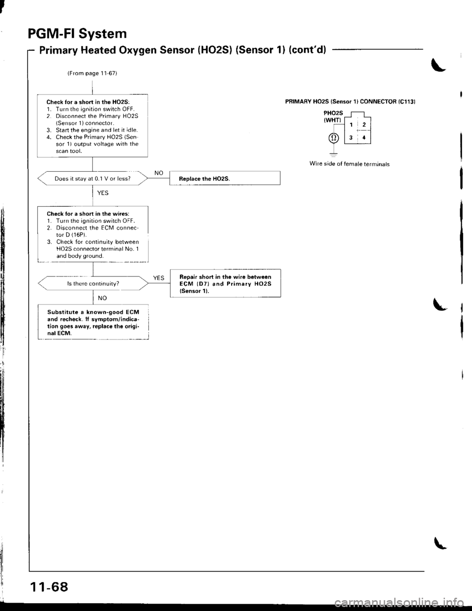
PRIMARY HO2S {Sensor'l} CONNECTOR (C1131
PHO2S T--rwHTl - --l
.l1 2ll1-{
0tls rl
Y,-I
Wire side of female terminals
Does it stay at 0.1 V or less?
Check lor a short in the wires:1. Turn the ignition switch OFF.2. Disconnect the ECM connector D (16P).
3. Check for continuity betweenHO2S connector terminal No. 1and body ground.
1 1-68
Check ror a short in the HO2S:1- Turn the ignition swilch OFF.2. Disconnect the Primary HO2S(Sensor 1) connector.3. Stan the engine and let it ;dle.4. Check the Primary HO2S (Sen
sor 1) output vohage with the
(From page '11 67i
Subslitute a known-good ECMand recheck. lf symptom/indica-tion goes away, replace lhe origi-nal ECM.
Page 274 of 1681
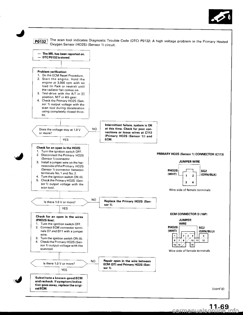
JThe scan tool indicates Diagnostic Trouble Code (DTC) P0132: A high voltage probtem in the primary HeatedOxygen Sensor (HO2S) (Sensor 1) circuit.
Problem veritication:1. Do th; ECM Reset procedure.
2. Start the engine. Hold theengine at 3,000 rpm with noload (in Park or neutral) untilthe radiator fan comes on,3. Test-drive with the A/T in Elposition, M/T in 4th gear.4. Check the Primary l-lO2S (Sen-sor 1) outprrt voltage with thescan tool during decelerationusrng comptetely closed throt-tle.
YES
Check tor an open in the HO2S:1. Turn the ignition switch OFF.2. Disconnectthe Primary HO2S(Sensorl)connector.
lnstall a jumper wire on the harness side ofthe Primary HO2S(Sensor 1) connector betweenterminals No.1 and No.2.Turn the ignition switch ON t).Check the Prjmary HO2S (Sen-sor'l) output voltage with thescan tool.
Intermittent failur€, svstem is OKat this time. Check for poor con-nectaons or loose wires at C113(Primary HO2S lsensor lll andECM.
5.
PRIMAnY HO2S {Sensor 1) CONNECTOR tC1t3l
PHO2S(WHT}
Wire side of female terminals
ECM CONNECTOR D (16PI
JUMPERWIREPHO2S(WHT)F;r=12 3 !l
sG2
5
./ 1012
13
(GBN/BLU)
Wire side of female terminals
(cont'd )
- The MIL has b€€n ieDorted on.- DTC P0132 isstored.
Replace the Primary HO2S (Sen-sor 11.ls there 1,0 V or more?
Check for an open in the wiros{PHO2S lin6):1. Turn the ignition switch OFF.2. Connect ECM connector termi-nals D7 and Dl1 with a jumper
3. Turn the ignition switch ON 0).4. Checkthe Primary HO2S (Sen-sor 1) output voltage with thescantool.
Repair open in the wire betweenECM (D7) end Primarv HO2S lsen-sor l).
ls there 1,0 V or more?
Substitute a known-good ECMand recheck. lf symptom/indica-tion goesaway. r€place th€ origi-nalECM.
1 1-69
Page 275 of 1681
PGM-FI System
Primary,Heated Oxygen Sensor (HO2S) (Sensor 1) (cont'dl
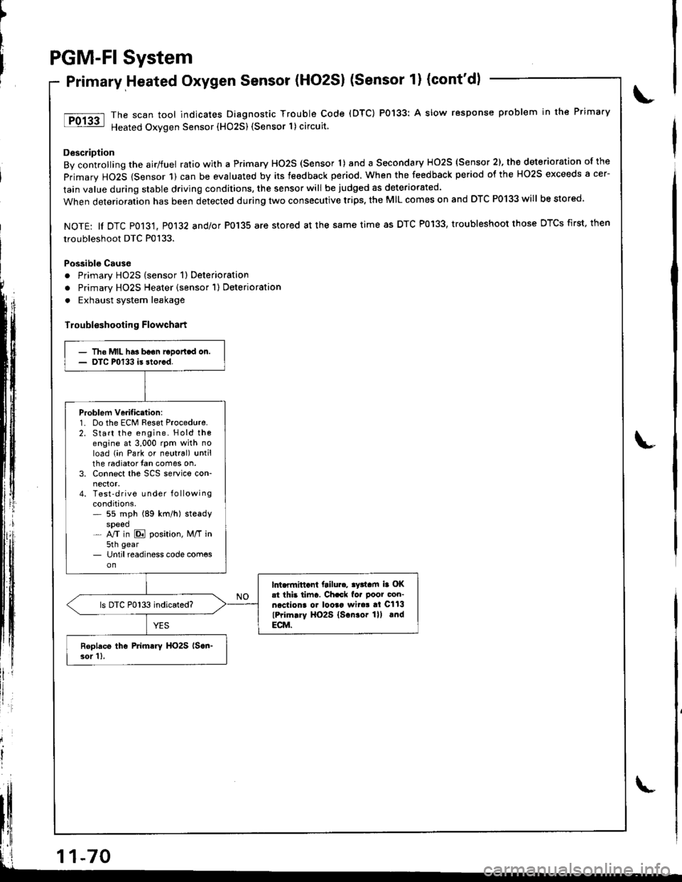
The scan tool indicates Diagnostic Trouble Code (DTC) P0133: A slow response problem in the Primary
Heated Oxygen Sensor (HO25) (Sensor 1) circuit.
Description
By controlling the airlfuel ratio with a Primary HO2S (Sensor 'l) and a Secondary HO2S (Sensor 2), the deterioration of the
primary HO2S {Sensor 1) can be evaluated by its teedback period. When the feedback period of the HO2S exceeds a cer-
lain value during stable driving conditions, the sensor will be judged as deteriorated.
When deterioration has been detected during two consecutive trips, the MIL comes on and DTC P0133 will be stored
NOTE: ll DTC P013't, P0132 and/or P0'135 are stored at the same time as DTC P0133, troubleshoot those DTCS first, then
troubleshoot DTC P0133.
Possible Cause
. Primary HO2S (sensor 1) Deterioration
o Primary HO2S Heater (sensor 1) Deterioration
. Exhaust system leakage
Troubl€shooting Flowchart
')
litll r
- Tho MIL has boon raDortcd on.- DTC P0133 is storcd.
Problem verificttion:1. Do the ECM Reset Procedure.2. Start the engine. Hold thoengine at 3,000 rpm with noload (in Park or neutral) untilthe radiator fan comes on.3. Connect the SCS service con-
4. Test'drive Lrnder f o llowingconditions.* 55 mph (89 km/h) steadyspeed- NT in E position, M/T in5th gear- Until readiness code com€son
lnt.flnittcnt ftilu... ay3tam ia OKat thb tiinr. Ch.ck fo. poor con-necliona o. looaa wita! al Cll3
lPrim.ry HO2S lscn.or lll lndECM.
ls DTC P0133 indicated?
Roplacs the Primary HO2S lscn-3or 1),
Page 276 of 1681
Secondary Heated Oxygen Sensor (HO2S) {sensor 2l
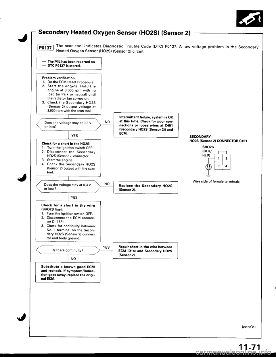
The scan tool indicates Diagnostic Trouble Code (DTC) P0137: A low voltage problem in the SecondaryHeated Oxygen Sensor (H02S) (Sensor 2) circuit.
(cont'd)
The MIL ha3 been reDorted on.DTC P0137 is storod.
Problem veritication:1. Do the ECM Reset Procedure.2. Start the engine. Hold theengine at 3,000 rpm with noload (in Park or neutral) untilthe radiator fan comes on,3. Check the Secondary H02S(Sensor 2) output voltage at3,000 rpm with the scan 1ool.
Inte.mittent failure, system is OKat lhb time. Ch6ck Ior ooor con-nections or loose wires at C451lSeconddry HO2S {Sensor 2)l andECM.
Does the voltage stay at 0.3 Vor less?
Check for a short in th€ HO2S:1. Turn the ignition switch OFF.2. Discon nect the SecondaryHO2S (Sensor 2) connector.3. Start the engine.4. Check the Secondary H02S(Sensor 2) output whh the scantool.
Does the voltage stay at 0.3 Vor less?
Check tor a short in the wire{SHO2S line):r. I urn rne rgnt on swttch uFF,2. Disconnect the ECM connec,tor D 116P).3. Check for continuity betweenNo. '1 terminal on the Secon-dary HO2S {Sensor 2) connector and body ground.
Ropair short in tho wira bctweenECM (D14) and Secondrry HO2S{Senso.2).
ls there continuity?
Substitute a known-good ECMand recheck. It symptom/indice-taon goes away, replace the origi-nel ECM.
SECONDARYHO2S (Sensor 2l CONNECTOR C451
sHo2sIBLU/REDI f- --
T-l 1 2ltr11(Or ls rl
L
Wire side oI fernale terminals
11-71
Page 277 of 1681
PGM-FI System
Secondary Heated Oxygen Sensor (HO2S) (Sensor 2l (cont'd)
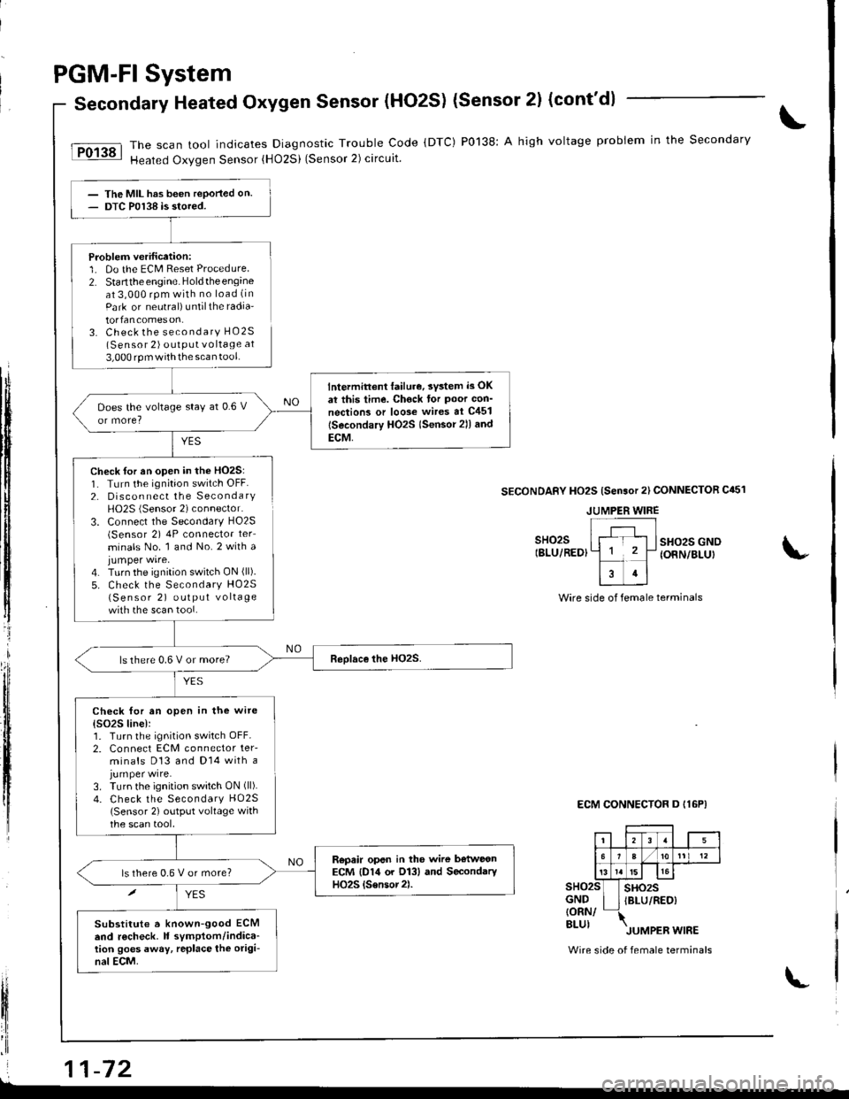
The scan tool indicates Diagnostic Trouble Code (DTC) P0138: A high voltage probiem in the Secondary
Heated Oxygen Sensor {HO2Si (Sensor 2) circuit.
YES
The MIL has been reported on.DTC P0138 is stored.
Problem verification:1. Do the ECM Reset Procedure2. Startthe engine. Holdtheengineat 3,000 rpm with no load (in
Park or neutral) untilthe radia'
torfancomeson.3. Check the secondary HO2S(Sensor 2) outPUt vo ltage at
3,000 rpm withthe scan tool.
lntermittent lailur€, svsted i3 OK
at this time. Chock tor Poor con'
nections or loo3e wires at C451
lSecondary HO2s lsensor 2ll and
ECM,
Does the voltage stay at 0.6 V
ls there 0.6 V or more?
Check for an open in the wite
{s()2S line):1. Turn the ignition switch OFF.2. Connect ECM connector ter-minals D13 and Dl4 with ajumper wire.3. Turn the ignition switch ON (ll).
4. Check the Secondary HO25(Sensor 2) output voltage withthe scan tool,
Repair opsn in the wire b€tweonECM {D14 or O13} and SecondaryHO2S {Sensor2).ls there 0,6 V or more?
Substitute a known-good ECMend r6check. It symptom/indica-tion goes away, rcplace the origi-nal ECM.
tI
t$
ffi
tljl'l
t,
lfi
il
fl'I
Check for an open in the HO2S:1. TLrrn the ignition switch OFF.2. Disconnect the SecondaryH02S (Sensor 2) connector.
3. Connect the Secondary HO2S(Sensor 2) 4P connector ter_
minals No. 1 and No.2 with ajumper wire.4. Turn the ignition switch ON (ll).
5. Check the Secondary HO25(Sensor 2) output vo lta ge
with the scan tool.
SECONDAFY HO2S {Sensor 2l CONNECTOR C451
sHo2sIBLU/REDIsHo2s GNOIONN/BLUI
Wire side of female terminals
ECM CONNECTOR D I16P}
sHo2sGND{ORN/BLUI
sHo2sIBLU/RED)
Wire side of female terminals
JUMPER WIRE
i 11-72L
Page 278 of 1681
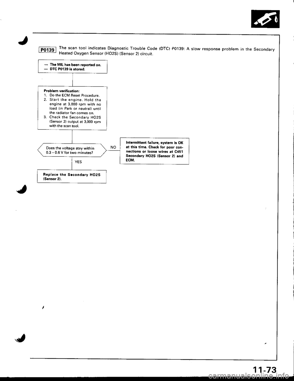
The scan tool indicates Diagnostic Trouble Code (DTC) P0139: A slow response problem in the SeconoarvHeated Oxygen Sensor (H02S) (Sensor 2) circuit.
The MIL has boen reDorted on.DTC P0139 b sto.od.
P.oblem ve tication:1. Do the ECM Reset Procedure.2. Start the engine. Hotd theengine at 3,000 rpm with noload (in Park or neutral) untilthe radiator fan comes on,3. Check the Secondary HO2S{Sensor 2) output ar 3,000 rpmth the scan tool.
Intarmittert lailurg, systsm i! OKat thi! time. Chsck for Door con-nections o. loose wi.es at C451Secondary HO2S lsonsor 2) .ndECM.
Does the voltage stay within0.3 - 0.6 V tortwo minutos?
Page 279 of 1681
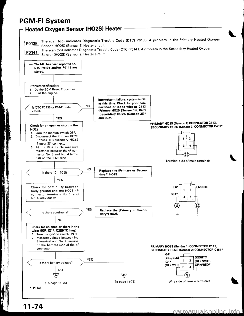
PGM-FI System
Heated Oxygen Sensor (HO2S) Heater
The scan tool indicates Diagnostic Trouble code (DTC) P0135: A problem in the Primary Heated oxygen
Sensor lHO2S) (Sensor 'l) Heater circuit
The scan tool indicates Diagnostic Trouble Code (DTC)P0141: A problem in the Secondary Heated Oxygen
Sensor {HO25) {Sensor 2) Heater circuit
Fo13sl
lFol4il
PRIMARY Ho2S (sen3or 1) CONNECToR C113,
SECONDARY HO2S (sensor 2l CONNECTOR Cil51'
Terminal side of male terminals
PRIMARY HO2S (SonSor 1l CONNECTOR Cl13,
SECONDARY HO2S lsan3or 2) CONNECTOR C451r
o2sHTC(BLK/WHT,
GRN/REO'}
IGP{YEL/BLK}lGlr(BLK/YEL)
(To page 11-75)*: P0141
- The MIL has been rePorted on- DTC P0135 and/or P0141 ate
stored.
Probl€m verilication:1. Do the ECM Reset Procedure
2. Start the engine.
lnt€rmitlent failure. 3vslem is OK
at this time. Check for Poo. con'
noction3 o. loose wire ai Cl13(Primary HO2S (S.nsor 1ll. gl51
lSocondary H02S lSensor 2))'
and ECM.
Check for an open or short in tho
HO2S:1. Turn the ignition switch OFF.2. Disconnect the Primary HO2S(Sensor 1) Secondary HO2S
{Sensor 2)'connector,3. At the HO2S side measureresistance between the 4P con-nector No. 3 and No. 4 terminals on the HO2S side.
ls there 10 - 40 0?
Check Ior continuity betweenbody ground and the HO2S 4P
connector lerminals No. 3 andNo.4 individually.
ls there continuity?
Ch€ck for an open or short in thewir63 (lGP, lG1*, O2SHTC lines):1. Turn the ignition switch ON (ll).
2. Measure voltage between No.3 terminal and No. 4 terminalon the harness side of the 4P
ls there batlery vohage?
{1o page 1l-75)Wire side of female terminals
Page 280 of 1681
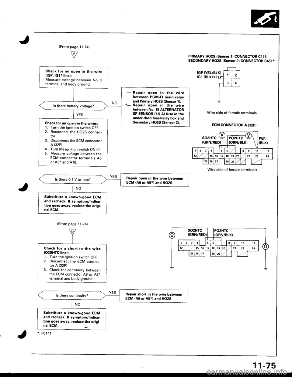
(From page 11-74)
Check tor an op6n in the wire{lGP, lGl* linel:Measure voltage between No. 3terminal and body ground.
Repair open in the wirebetween PGM-Fl mein relayand Pii.nary HO2S {Sonsor 11.Repair open in the wirebetween No. 15 ALTERNATORSP SENSOR 17.5 A) tuse in theund€r-d.sh fuse/rolav box andSecondary HO2S (S€n3or 21.
ls there battery vohage?
Check for an opon in the wh$:1. Turn the ignition switch OFF.2. Reconnect the HO2S connec-tor.3- Disconnect the ECM connectorA (32P).
4. Turn the ignition switch ON 1fl).5. Measure voltage between theECM connector terminals 46or A5* and A10.
Repair open in tha wire betw.enECM {A6 or A5rl and HO2S.ls there 0.1 V or less?
Substitute a known-good ECMand r.chcck. tf 3ymptom/indica-tion goes awey, repl.ce the odgi-nelECM.
PRIMARY HO2S {Sensor 1} CONNECTOR C113SECONDARY HO2S (Sensor 2ICONNECTOR C45tr
Wire side of female terminals
ECM CONNECTOR A I32P)
IGPlG1
so2HTC{GRN/RET
c
4tr
A, 4\'/ | PO2HTC \=/ \ltoRN/BLKt \-T--] \
PGl(BLK)
2a 1f lefil tt12't5t51? t8t92022 23
2526l2823
Wire side of temale terminals
(From page '11-74)
Check fo. a short in the wire(O2SHTC linel:1. Turn the ignition switch OFF.2. Disconnect the ECM connec-tor A (32P).
3. Check for continuity betweenthe ECM connector 46 or A5*termanai and body ground.
Rcpair short in the wire botweenECM IAG or A5*l .nd HO2S.ls there continuity?
Substituto a known-good ECMand recheck. lf symptom/indica-tion goes away, replac€ the origi-nalECM.
3 rl 15 6
15 15 17 lA
*r P0141
11-75