service HONDA INTEGRA 1998 4.G Owner's Manual
[x] Cancel search | Manufacturer: HONDA, Model Year: 1998, Model line: INTEGRA, Model: HONDA INTEGRA 1998 4.GPages: 1681, PDF Size: 54.22 MB
Page 235 of 1681
![HONDA INTEGRA 1998 4.G Owners Manual System Description
System Connectors [Dash and Floor] (contd]
c405SERVICECHECK
c410(ECM.DICilo9{ECM-C)tL
REAR WIREHARNESS
,n
, ?l
1 1-30
L HONDA INTEGRA 1998 4.G Owners Manual System Description
System Connectors [Dash and Floor] (contd]
c405SERVICECHECK
c410(ECM.DICilo9{ECM-C)tL
REAR WIREHARNESS
,n
, ?l
1 1-30
L](/img/13/6069/w960_6069-234.png)
System Description
System Connectors [Dash and Floor] (cont'd]
c405SERVICECHECK
c410(ECM.DICilo9{ECM-C)tL
REAR WIREHARNESS
,n
, ?l
1 1-30
L
Page 237 of 1681
t-
il
Troubleshooting ".
Troubleshooting Proccdures
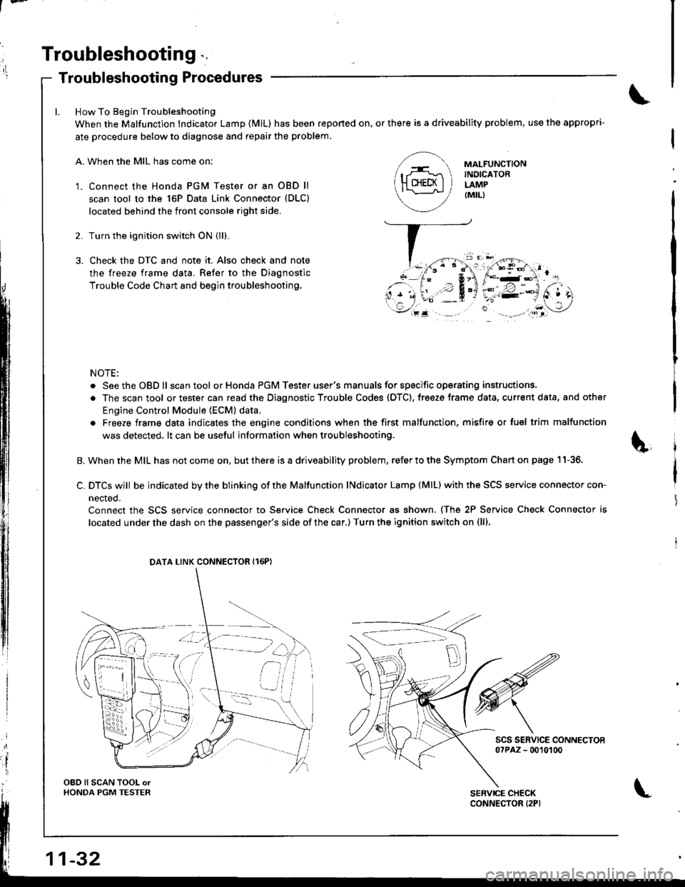
How To Begin Troubleshooting
When the Malfunction lndicator Lamp {MlL) has been reponed on, or there is a driveability problem, use the appropri-
ate procedure below to diagnose and repair the problem.
A. When the MIL has come on:
'1. Connect the Honda PGM Tester or an OBD ll
scan tool to the 16P Data Link Connector (DLC)
located behind the front console right side.
2. Turn the ignition switch ON (ll).
3. Check the DTC and note it. Also check and note
the freeze frame data. Refer to the Diagnostic
Trouble Code Chart and begin troubleshooting.
NOTE:
. SeetheOBDll scantool or Honda PGM Tester user's manuals for specific operating instructions.
. The scan tool or tester can read the Diagnostic Trouble Codes (OTC). freeze frame data, current data, and other
Engine Control Module (ECM) data.
. Freeze frame data indicates the engine conditions when the first malfunction, misfire or luel trim malfunction
was detected. lt can be useful information when troubleshooting.
B. When the MIL has not come on, but there is a driveability problem, refer to the Symptom Chart on page 11-36.
C. DTCS wjll be indicated by the blinking of the Malfunction lNdicator Lamp {MlL) with the SCS service connector con-
nected.
Connect the SCS service connector to Service Check Connector as shown. (The 2P Service Check Connector is
located under the dash on the passenger's side of the car,) Turn the ignition switch on (lll.
scs sERvlcE coNNEcToEo?PAZ - 0010100
MAI-FUNCTIONINDICATORLAMP{MIL)
DATA LINK CONNECTOR Il6PI
OBO ll SCAN TOOL orHONDA PGM TESTER
Page 238 of 1681
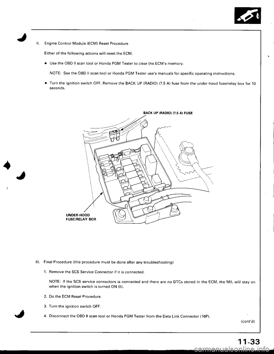
Engine Control Module (ECM) Reset Procedure
Either of the following actions will reset the ECM.
. Use the OBD ll scantool or Honda PGM Tester to clear the ECM'S memory.
NOTE: See the OBD ll scan tool or Honda PGM Tester use's manuals for specific operating instructions.
. Turn the ignition switch OFF. Remove the BACK UP (RADIO) (7.5 AI tuse from the under hood fuse/relay box for 10seconds.
BACK UP (RAOIO) {7.5 AI FUSE
UNDER'HOODFUSE/RELAY BOX
lll. Final Procedure (this procedure must be done after any trou bleshooting )
1. Remove the SCS Service Connector if it is connected.
NOTE: lf the SCS service connectors is connected and there are no DTCS stored in the ECM, the MIL will stav onwhen the ignition switch is turned ON (ll).
2. Do the ECM Reset Procedure.
3. Turn the ignition switch OFF.
4. Disconnect the OBD ll scan tool or Honda PGM Tester from the Data Link Connector (16P|.
{cont'd)
11-33
Page 245 of 1681
I
t
h,,l,!
il
Troubleshooting
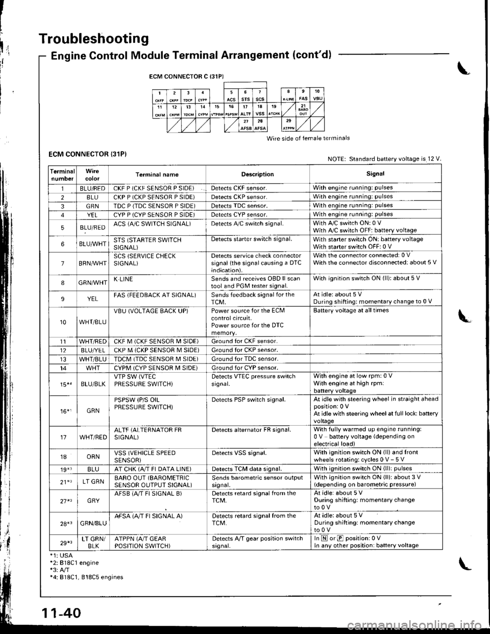
ECM CONNECTOR {31P)
Engine Control Module Terminal Arrangement (cont'd)
ECM CONNECTOR C {31P)
235srsscs1112t31515t71A19
2A
Wire side of lemale terminals
NOTE: Standard battery voltage is 12 V.
TerminalnumbercolorTerminal namoD6scriptionSignal
1BLU/REDCKF P (CKF SENSOR P SIDE)Detects CKF sensor.With engine running: pulses
28LUCKP P (CKP SENSOR P SIDE)Detects CKP sensor.With engine running: pulses
3GRNTDC P {TDC SENSOR P SIDE)Detects TDC sensor,With engine running: pulses
YELCYP P (CYP SENSOR P SIDE)Detects CYP sensor,With engine running: pulses
5BLU/REDACS (AJC SWITCH SIGNAL)Detects A,/C switch signal.With A,/C switch ON: 0 VWith A,/C switch OFF: battery voltage
6BLUA/VHTSTS (STARTEB SWITCHSIGNAL)
Detects starter switch signal.With staner switch ON: battery voltageWith starter switch OFF: 0 V
7BRN,AiVHTSCS (SERVICE CHECKSIGNAL)Detects service check connectorsignal (the signalcausing a DTC;ndication).
With the co n nector con nected: 0 VWath the connector disconnected: about 5 V
8GRNAVHTK LINESends and receives OBD ll scantool and PGM tester signal.With ignition switch ON (ll): about 5 V
9YELFAS lFEEDBACK AT SIGNAL)Sends feedback signal for theTCM,At idle: about 5 VDuring shifting: momenlary change to 0 V
10WHT/BLU
VBU (VOLTAGE BACK UP)Power source for the ECMcontrolcircuit,Power source for the DTC
Battery voltage at all times
t1WHT/REDCKF M (CKF SENSOR I\4 SIDE)Ground for CKF sensor.
12BLUI/E LCKP M (CKP SENSOR M SIDE)Ground for CKP sensor.
WHT/BLUTDCM (TDC SENSOR M SIDE)Ground tor TDC sensor.
14CYPM (CYP SENSOR M SIDE)Ground for CYP sensor.
15*.BLU/BLKVTP SW (VTEC
PRESSUFE SWITCH)Detects VTEC pressure switchsr9nal.
With engine at low rpm:0 VWith engine at high rpmlbattery voltaqe
161,GRN
PSPSW (P/S OILPRESSURE SWITCH)Derecls PSP switch signal.At idle with steering wheel in straight aheadpositioni 0 VAt idle with steering wheelat full lock: batteryvoltage
17WHT/REDALTF (ALTERNATOR FRSIGNAL)Detects alternator FR signal.With fully warmed up engine running:0 V battery voltage (depending onelectrical load)
18ORNVSS (VEHICLE SPEEDSENSORiDetects VSS signal.With ignition switch ON (ll) and lrontwheels rotating: cycles 0 V- 5 V
19*3BLUAT CHK (A/T FI DATA LINE)Detects TCM data signal.With ignition switch ON (ll)i pulses
21*LT GRNBARO OUT (SAROMETRIC
SENSOR OUTPUT S!GNAL)Sends barometric sensor outputsrgnal,With ignition switch ON (ll): about 3 V(depending on barometric pressure)
27 x3GRYAFSB (A"/T FI SIGNAL B)Detects retard signal from theTCM,At idle: about 5 VDuring shifting: momentary changeto0V
28+1GRN/8LUA+SA (A/T FI SIGNAL A)Detects retard signal from theTCM.At idle: about 5 VDuring shifting: momentarV changeto0V
29+3LT GRN/BLKATPPN (A/T GEARPOSITION SWITCH)Detects A,/T gear position switchsrgnal-In E orE positionr 0VIn anv other position: battery voltage
*1: USA*2:818C1 engine*3: A/T*4: 818C1, 818C5 engines
Page 247 of 1681
1l
Troubleshooting
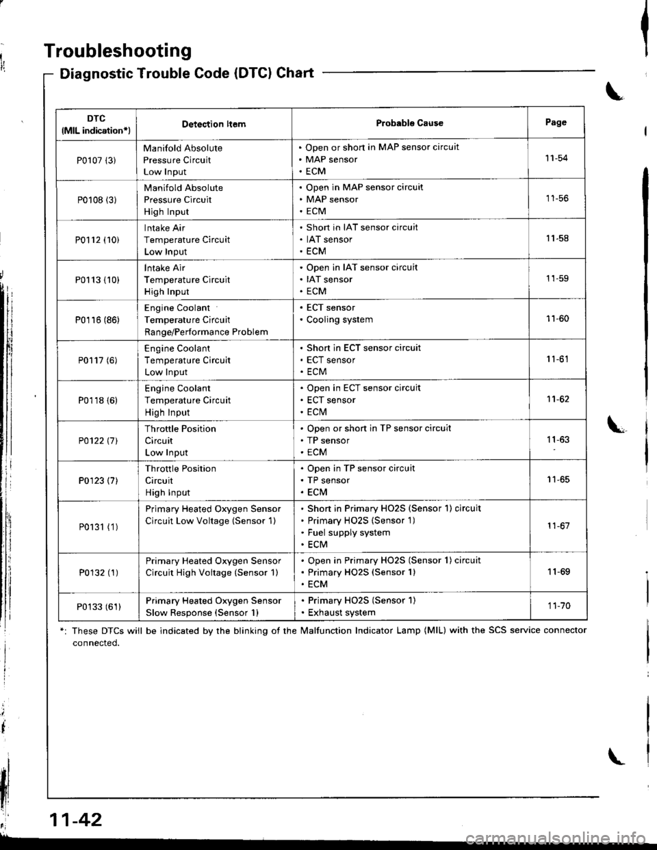
Diagnostic Trouble Gode (DTCI Chart
*: These DTCS will be indicated by the blinking ot the lvalfunction Indicator Lamp (MlL) with the SCS service connector
connected.
Ia
\
\
il
\
DTC
lMlL indication*lDetection ltemProbabls CausePage
P0107 (3)
Manifold Absolute
Pressure Circuit
Low Input
Open or short in MAP sensor circuit
MAP sensor
ECM
'11-54
P0108 (31
Manifold Absolute
Pressure Circuit
High Input
Open in MAP sensor circuit
MAP sensor
ECM
tt-5t,
P0112 (10)
Intake Air
Temperature Circuit
Low Input
Short in IAT sensor circuit
IAT sensor
ECM
11.58
P0113 {10)
lntake Air
Temperature Circuit
High Input
Open in IAT sensor circuit
IAT sensor
ECM
1'�1-59
P0116 (86)
Engine Coolant
Temperature Circuit
Range/Performance Problem
. ECT sensor' Cooling system11-60
P0117 (6)
Engine Coolant
Temperature Circuit
Low Input
Short in ECT sensor circuit
ECT sensor
ECM
1 '�t-61
P0118 {6)
Engine Coolant
Temperature Circuit
High Input
Open in ECT sensor circuit
ECT sensor
ECt\,4
1't -62
P0122l7l
Throttle Position
Circuit
Low Input
Open or shon in TP sensor circuit
TP sensor
ECM
11,63
P0123 (7)
Throttle Position
Circuit
High Input
Open in TP sensor circuit
TP sensor
ECM
I t-oc
P0131 (1 )
Primary Heated Oxygen Sensor
Circuit Low Voltage (Sensor 1)
Shon in Primary HO2S (Sensor'l) circuit
Primary H02S {Sensor 1)
Fuel supply system
ECM
11-67
P0132 (1)Primary Heated Oxygen Sensor
Circuit High Voitage (Sensor 1)
Open in Primary HO2S (Sensor 1) circuit
Primary HO2S (Sensor 1)
ECM
11-69
P0133 (61)Primary Heated Oxygen Sensor
Slow Response (Sensor 1)
. Primary HO2S (Sensor 1). Exhaust system1 1-70
,r:' 11-42
L
Page 254 of 1681
3.Fuel Cut-off Control
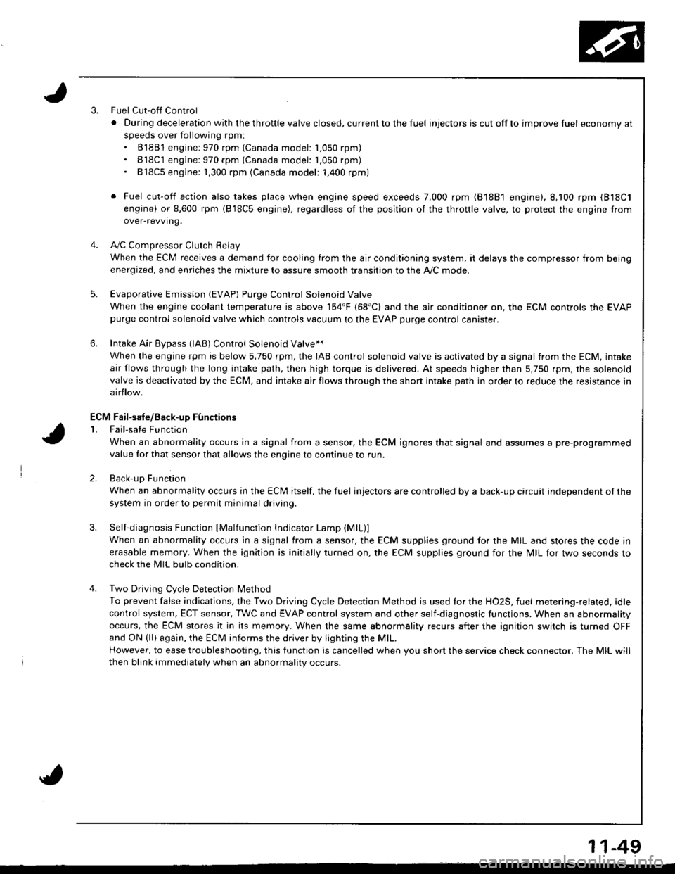
. Du ring dece leration with the th rottle va lve closed, cu rrent to the fuel injectors is cutoffto improvefuel economyat
speeds over following rpm:. B'1881 engine: 970 rpm {Canada model: 1.050 rpm). B18C1 engine:970 rpm {Canada model: 1.050 rpm). 818C5 engine: 1,300 rpm (Canada model: 1,400 rpm)
. Fuel cut-off action also takes place when engine speed exceeds 7,000 rpm (B'1881 engine), 8.100 rpm (818C1
engine) or 8,600 rpm (818C5 engine), regardless ol the position of the thronle valve, to protect the engine from
over-revving.
A,,/C ComDressor Clutch Relav
When the ECM receives a demand for cooling from the air conditioning system, it delays the compressor from being
energized, and enriches the mixture to assure smooth transition to the A,/C mode.
Evaporative Emission (EVAP) Purge Control Solenoid Valve
When the engine coolanl temperature is above '154'F (68'C) and the air conditioner on. the ECM controls the EVAPpurge control solenoid valve which controls vacuum to the EVAP purge control canister.
Intake Air Eypass (lAB) Control Solenoid Valve*a
When the engine rpm is below 5,750 rpm, rhe IAB control solenoid valve is activated by a signal from the ECM, intake
air flows through the long intake path, then high torque is delivered. At speeds higher than 5,750 rpm, the solenoidvalve is deactivated by the ECM, and intake air flows through the short intake path in order to reduce the resistance in
airflow.
Sell-diagnosis Function lMalfunction Indicator Lamp {MlL)lWhen an abnormality occurs in a signal from a sensor, the ECM supplies ground for the MIL and stores the code in
erasable memory. When the ignition is initially turned on, the ECM supplies ground for the N4lL tor two seconds to
check the MIL bulb condition.
Two Driving Cycle Detection Method
To prevent false indications, the Two Driving Cycle Detection Method is used for the HO2S, fuel metering-related, idle
control system, ECT sensor, TWC and EVAP control system and other self-diagnostic functions, When an abnormality
occurs, the ECM stores it in its memory. When the same abnormality recurs after the ignition switch is turned OFFand ON (ll)again, the ECM informs the driver by lighting the MlL.
However, to ease troubleshooting, this function is cancelled when you shon the service check connector. The MIL will
then blink immediately when an abnormality occurs.
4.
5.
6.
3.
4.
ECM Fail-safe/8ack.up F0nctions
1. Fail-sate Function
When an abnormality occurs in a signal from a sensor, the ECM ignores that signal and assumes a pre-programmed
value for that sensor that allows the enqine to continue to run.
2. Back-uo Function
When an abnormality occurs in the ECM itself, the fuel injectors are controlled by a back-up circuit independent of the
system in order to permit minimal driving.
11-49
Page 256 of 1681
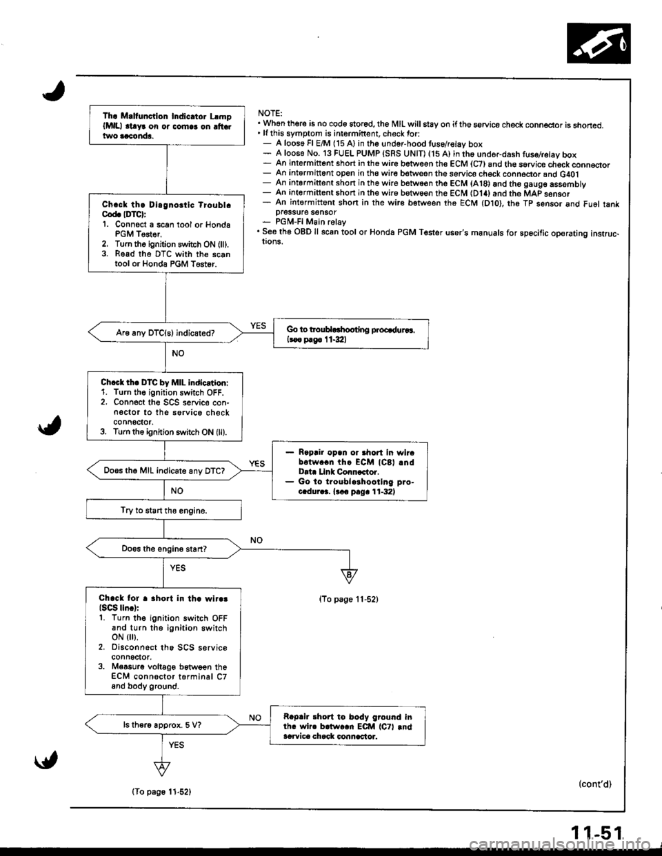
NOTE:. Whon there is no cod6 stored, the MIL willstay on iftho aorvice check conn€ctor is snoned.' lfthis symptom is intermittent. check tor:- A loos6 Fl E/M (15 A) in the undor-hood tuse/relav box- A loose No. 13 FUEL PUMP {SRS UNIT) (15 A) in th6 under-dash fuse/retay box- An intermitt6nt short in the wir€ betwesn the ECM (C7) and th€ sorvice chock conn€qor- An intormittent open in the wire between the sorvice chsck conneclor and G40l- An intermittent short in the wire betwo€n the ECM (A18) and the gaug6 assemDry- An intermittent shon in the wir6 between the ECM (D14) and the MAP sonsor- An intermittent shon in the wire bstween the ECM (Dto), th6 Tp sensor and Fu6l tankpI6SSU16 SOnSOT- PGM-FI Main relay. See th6 OBD ll scan tool or Honda PGM Tester user's manuals for sp6cific operating instruc-!ons.
(To page 11-52)
(cont'd)
Th. M.lfunction Indic.tor LlmplMlll .t!yr on or comlr on ltt .two aaconda.
Ch.ck th! Dirgnoitic tioubl.Cod. IDTC):'1. Connoct a 6can tool or HondaPGM Tester,2. Turn tho ignition switch ON (ll).3. Read tho DTC with the scantool or Honda PGM T6st6r.
Go to trouHorhooting proQduaaa.
koo p.g6 I 1.3:ll
Ch.ct th. DTC by MIL indication:1. Turn th€ ignition switch OFF.2. Connect the SCS seNic€ con-n€ctor to the sorvico checkconnoctor,3. Turn the ignition s1\,itch ON (ll).
Rapair opan or ahort in wirabotw..n thg ECM lCSl .ndData Llnk Conncctor.Go lo troublcrhootlng pro-c.dur.3. {.co pag. 11-32)
Do.s th6 MIL indicate anv DTC?
Try to start tho engine.
Chack lor r 3hort in th. wlr.3lsqg lln.):1. Turn the ignition switch OFFand turn the ignition switchoN { },2. Disconnect th6 SCS serviceconnector,3. M€a6urg voltaOe between theECM connoctor torminal C7and body ground.
Rapah 3hort to body ground inlh. wir. b.lw..n ECM lCTl .ndacwica chack connactor.
ls ther6 approx. 5 V?
\{,
(To page 11-52)
11-51
Page 275 of 1681
PGM-FI System
Primary,Heated Oxygen Sensor (HO2S) (Sensor 1) (cont'dl
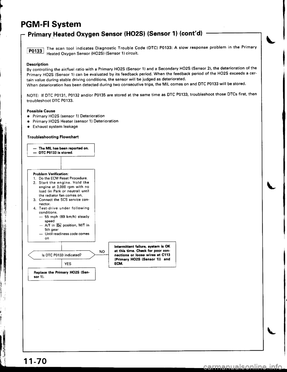
The scan tool indicates Diagnostic Trouble Code (DTC) P0133: A slow response problem in the Primary
Heated Oxygen Sensor (HO25) (Sensor 1) circuit.
Description
By controlling the airlfuel ratio with a Primary HO2S (Sensor 'l) and a Secondary HO2S (Sensor 2), the deterioration of the
primary HO2S {Sensor 1) can be evaluated by its teedback period. When the feedback period of the HO2S exceeds a cer-
lain value during stable driving conditions, the sensor will be judged as deteriorated.
When deterioration has been detected during two consecutive trips, the MIL comes on and DTC P0133 will be stored
NOTE: ll DTC P013't, P0132 and/or P0'135 are stored at the same time as DTC P0133, troubleshoot those DTCS first, then
troubleshoot DTC P0133.
Possible Cause
. Primary HO2S (sensor 1) Deterioration
o Primary HO2S Heater (sensor 1) Deterioration
. Exhaust system leakage
Troubl€shooting Flowchart
')
litll r
- Tho MIL has boon raDortcd on.- DTC P0133 is storcd.
Problem verificttion:1. Do the ECM Reset Procedure.2. Start the engine. Hold thoengine at 3,000 rpm with noload (in Park or neutral) untilthe radiator fan comes on.3. Connect the SCS service con-
4. Test'drive Lrnder f o llowingconditions.* 55 mph (89 km/h) steadyspeed- NT in E position, M/T in5th gear- Until readiness code com€son
lnt.flnittcnt ftilu... ay3tam ia OKat thb tiinr. Ch.ck fo. poor con-necliona o. looaa wita! al Cll3
lPrim.ry HO2S lscn.or lll lndECM.
ls DTC P0133 indicated?
Roplacs the Primary HO2S lscn-3or 1),
Page 285 of 1681
PGM.FI
Misfire
System
Detected in One Cylinder (cont'd)
)
Troubleshooting Flowchart
ff
i
)
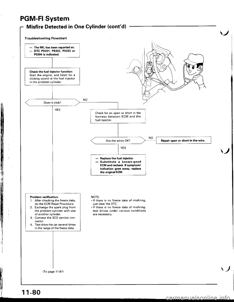
NOTE:.lf there is no freeze data of misliring,just clear the DTC.'lf there is no freeze data of misfiring,test drives under various conditions
The MIL has b6€n reported on.DTC P0301, P0302, P0303 0rP0304 is indicated.
Check the fuel iniector function:Stan the engine, and listen for aclicking sound at the fuel injectorin the problem cylinder.
Check for an open or shon in theharness between ECM and thefUel injector.
Repair open or short in the wiro.
- Replace tho luel inisctor.- Sub3titute a known-goodECM and rach€ck. It symptom/indicrtion 90e3 away, replacethe original ECM.
Problem ve.ification:1. After checking the freeze data,do the ECM Reset Procedure.2. Exchange the spark plug fromthe problem cylinder with oneof another cylinder.3. Connect the SCS service connector.4. Test-drive the car several timesin the range of the treeze data.
(To page 11-81)
Page 291 of 1681
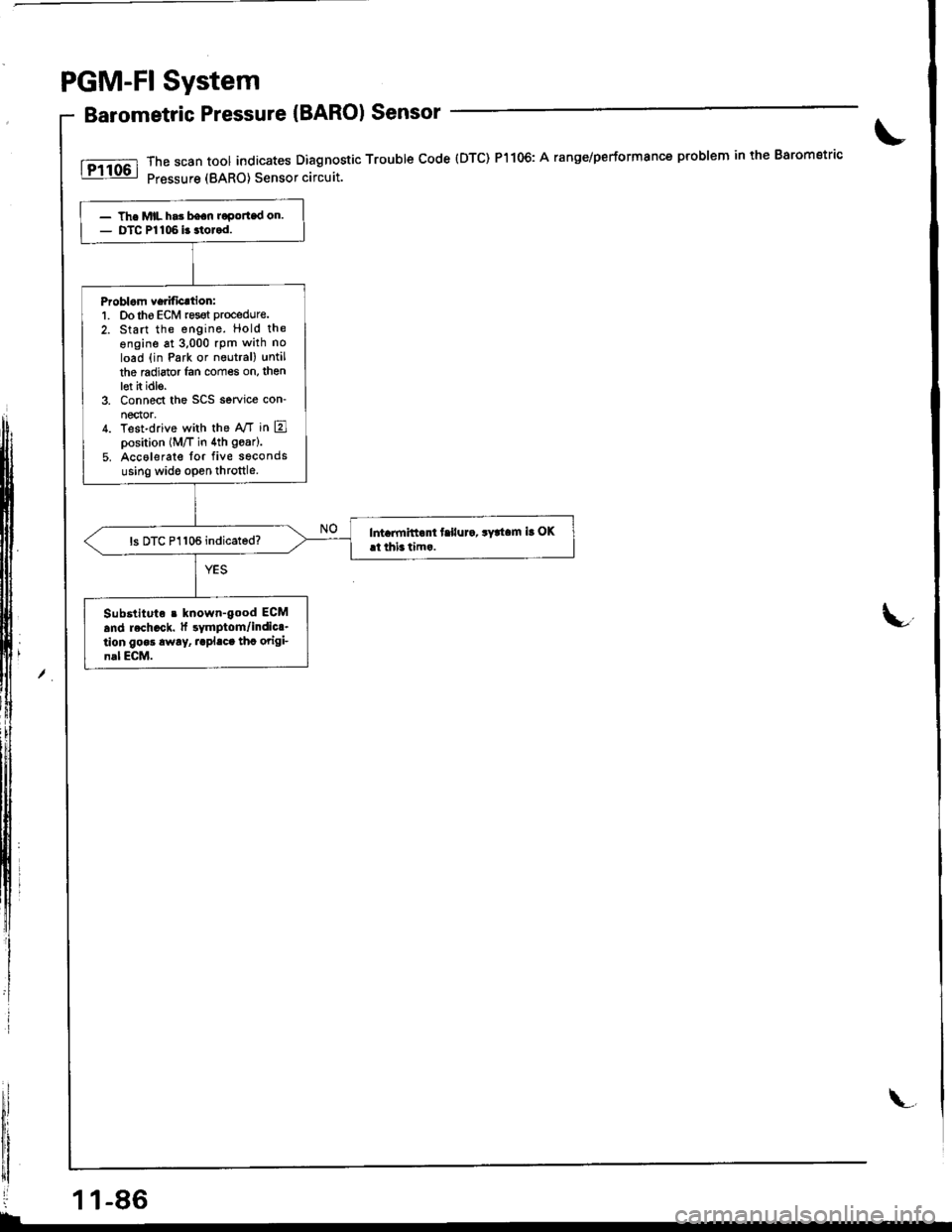
PGM-FI System
Barometric Pressure {BARO) Sensor
rrt*l ;:"""::::[Ti5li"$::::#nostic
rroubre code (Drc) P1106: A ranse/performance p'oblem in the Barometric\
,xl
lu,
i-
- The MIL h.3 bean roportad on.- DTC Pl106 i3 3tolod.
Problom Ye.ification:1. Dotho ECM resot procedure.
2. Start the engine. Hold the
ongine at 3,000 rpm with no
load (in Park or neutral) until
the mdiator lan comes on, thenlet h idle.3. Connect the SCS service con-
nector,4. Test-drive with the A,/T in E]position (M/T in 4th goar).
5. Accolerate for five seconds
using wide open throttle.
Int imitt.nt f.llur., .y!t.m ir OKrt thi. tim..ls DTC P1106 indicated?
Substltuto r known-good EGM
and rech.ck. tf rymptom/indic..lion gooa rway, raplaca thc origi_n.l ECM.
11-86
\.