service HONDA INTEGRA 1998 4.G Service Manual
[x] Cancel search | Manufacturer: HONDA, Model Year: 1998, Model line: INTEGRA, Model: HONDA INTEGRA 1998 4.GPages: 1681, PDF Size: 54.22 MB
Page 388 of 1681
|'I
Mainshaft Assembly
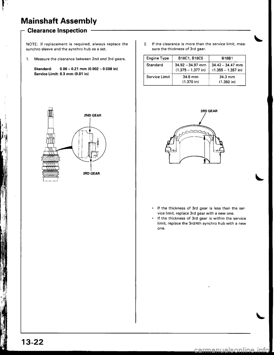
Glearance Inspection
NOTE: lf replacement is required, always replace the
svnchro sleeve and the svnchro hub as a set.
'L Measure the clearance between 2nd and 3rd qears.
Standard: 0.05 - 0.21 mm (0.002 - 0.C08 in)
Service Limit: 0.3 mm 10,01 inl
13-22
Engine Type818C1.818C5818B 1
Standard34.92 - 34.97 mm
{l.375 - 1.377 in)
34.42 - 34.47 mm(1.355 - 1.357 in)
Service Limit34.8 mm
(1.370 in)
34.3 mm(1.350 in)
2. It the clearance is more than the service limit, mea-
sure the thickness of 3rd gear.
li the thickness of 3rd gear is less than the ser-
vice limit, replace 3rd gear with a new one.
lf the thickness of 3rd gear is within the service
limit, replace the 3rd/4th synchro hub with a new
one.
3RD GEAR
Page 389 of 1681
4.
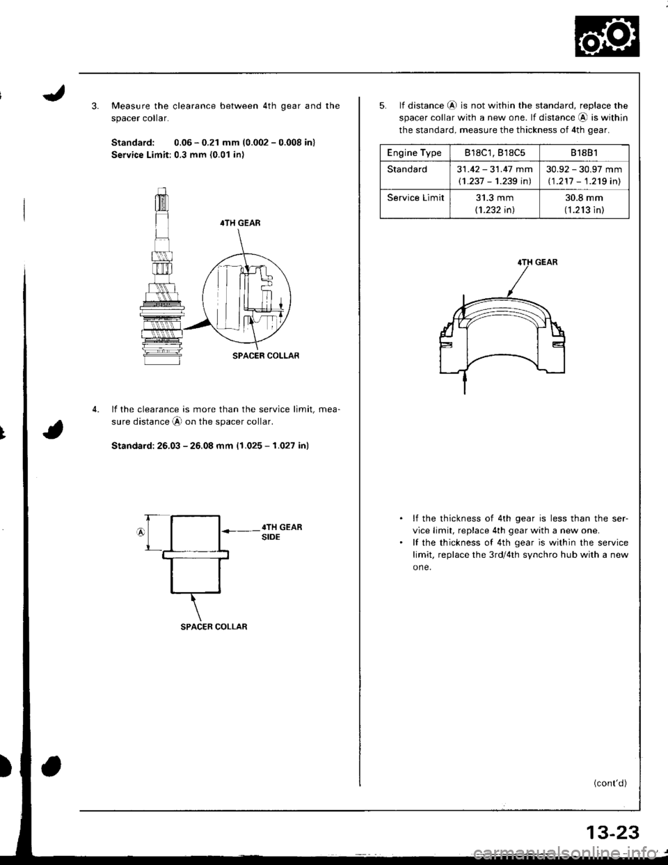
Measure the clearance between 4th qear and the
spacer colar.
Standard: 0.06 - 0.21 mm (0.002 - 0.008 in)
Service Limit:0.3 mm (0.01 in)
4TH GEAR
SPACER COLLAR
lf the clearance is more than the service limit, mea-
sure distance A on the spacer collar.
Standard: 26.03 - 25.08 mm (1.025 - 1.027 in)
SPACER COLLAR
Engine Type818C1, B'�l8C581881
Standard31 .42 - 31.47 mm
(1 .237 - 1.239 inl
30.92 - 30.97 mm
11 .211 - 1.2'tg inl
Service Limit31.3 mm
11.232 inl
30.8 mm
(1.213 in)
5. lf distance @ is not within the standard, replace the
spacer collar with a new one. lf distance @ is within
the standard, measure the thickness of 4th gear.
lf the thickness of 4th gear is less than the ser-
vice limit, replace 4th gear with a new one.
lf the thickness of 4th gear is within the service
limit, replace the 3rd/4th synchro hub with a new
one.
(cont'd)
13-23
Page 390 of 1681
Mainshaft Assembly
Clearance Inspection (cont'dl
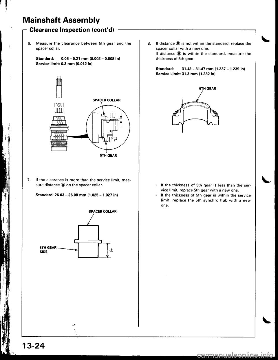
Measure the clearance between sth qear and
50acer collar.
Standard: 0.06 - 0.21 mm (0.002 - 0.008 in)
S€rvica limit: 0.3 mm {0.012 inl
the8. lf distance (9 is not within the standard, replace the
spacer collar with a new one.
lf distance @ is within the standard, measure the
thickness of sth gear.
Standard: 31.42 -31.17 mm (1.237 - 1.239 inl
Service Limit:31.3 mm {1.232 inl
7.lf the clearance is more than the service limit, mea-
sure distance @ on the spacer collar.
Stsndard: 26.03 - 26.08 mm (1.025 - 1.027 in)
lf the thickness of sth gear is less than the ser-
vice limit, replace 5th gear with a new one.
lf the thickness of sth gear is within the service
limit, replace the 5th svnchro hub with a new
one.
SPACER COI-LAR
sTH GEAR
5TH GEAR
Page 392 of 1681
I
Mainshaft Assembly
Inspection
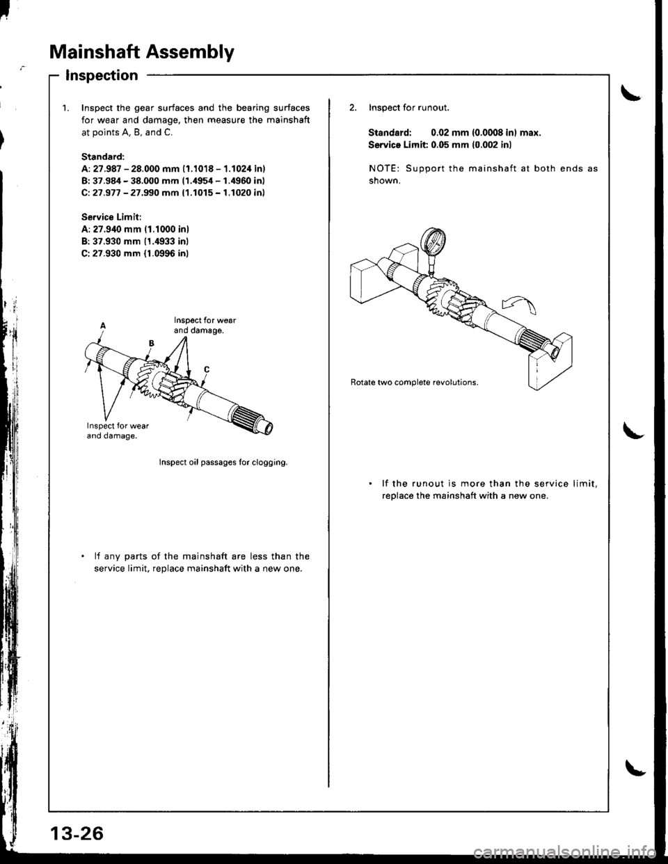
\1.Inspoct the gear surfaces and the bearing surfaces
for wear and damage, then measure the mainshaft
at points A. B, and C.
Standard:
A: 27.987 - 28.000 mm (1.1018 - 1.1024 inl
B: 37.984 - 38.000 mm 11.4954 - 1.4960 inl
Ci 27 .977 - 27 .99O mm { 1.1015 - 1.1020 inl
Se.vice Limit:
A: 27.940 mm 11.1000 inl
B:37.930 mm 11.4933 inl
C:27.930 mm {1.0996 inl
2. Inspect for runout.
Standard: 0.02 mm 10.0008 inl max.
Service Limit 0.05 mm (0.002 inl
NOTE: Support the mainshaft at both ends
shown.
lnspect oil passages for clogging.
lf the runout is more than the service limit,
reolace the mainshaft with a new one.
lf any parts of the mainshaft are less than the
service limit, reDlace mainshaft with a new one.
Page 395 of 1681
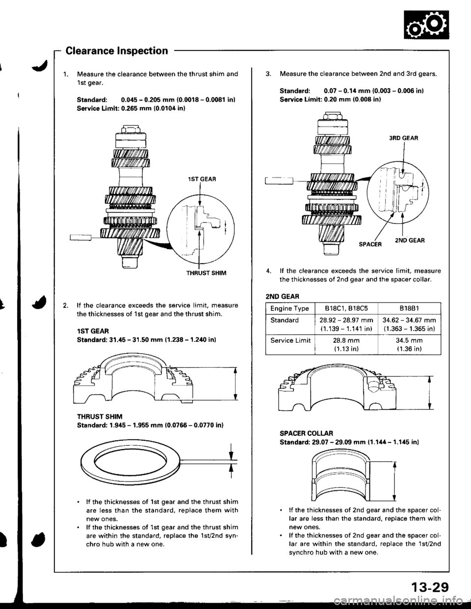
1.Measure the clearance between the thrust shim and
1st gear.
Standard: 0.045 - 0.205 mm (0.0018 - 0.0081 in)
Service Limit:0.265 mm {0.0104 in}
3. Measure the clearance between 2nd and 3rd gears.
Standard: 0.07 - 0.14 mm {0.003 - 0.006 inl
Service Limit: 0.20 mm (0.008 in)
4. lf the clearance exceeds the service limit, measure
the thicknesses of 2nd gear and the spacer collar.
2ND GEAR
lf the clearance exceeds the service limit, measure
the thicknesses of 1st gear and the thrust shim.
lST GEAR
Standard: 31./t5 - 31.50 mm (1.238 - 1.2i10 in)
THRUST SHIM
Standard: 1.945 - 1.955 mm (0.0766 - 0.0770 inl
SPACER COLLAR
Stand.rd: 29.07 - 29.09 mm 11.1'+4 - 1.1,15 inl
lf the thicknesses of 1st gear and the thrust shim
are less than the standard, replace them with
new ones,
lf the thicknesses of 1st gear and the thrust shim
are within the standard, replace the 1sv2nd syn-
chro hub with a new one,
lf the thicknesses of 2nd gear and the spacer col-
lar are less than the standard, reDlace them with
new ones.
lf the thicknesses of 2nd gear and the spacer col-
lar are within the standard, replace the 1sv2nd
synchro hub with a new one.
THRUST SHIM
Engine TypeB18C1, 818C581881
Standard2a.92 - 28.97 mm
(1.139 - 1.141 in)
34.62 - 34.67 mm(1.363 - 1.365 in)
Service Limit28.8 mm(1.13 in)
34.5 mm(1.36 in)
Page 397 of 1681
I
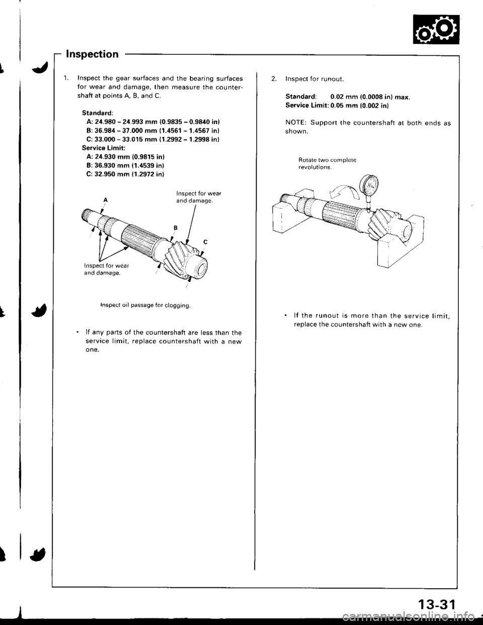
t
Inspect the gear surfaces and the bearing surfaces
for wear and damage, then measure the counter-
shaft at points A. B, and C.
Standard:
A: 24.980 - 24.993 mm {0.9835 - 0.9840 inl
B: 36.984 - 37.000 mm 11.4561 - 1.4557 inl
C: 33.000 - 33.015 mm (1.2992 - 1.2998 inl
Service Limit:
A: 24.930 mm {0.9815 inl
B:36.930 mm (1.4539 in)
C: 32.950 mm {.1.2972 inl
Inspect oil passage for clogg;ng.
lf any parts of the countershaft are less than the
service limit, replace countershaft with a new
one.
ano oamage,
I
2.Inspect for runout.
Standardr 0.02 mm (0.0008 in) max.
Service Limit:0.05 mm (0.002 in)
NOTE: Support the countershaft at both ends
shown.
Rotate two complete
lf the runout is more than the service limit,
replace the countershaft with a new one.
13-31
-,i
Page 401 of 1681
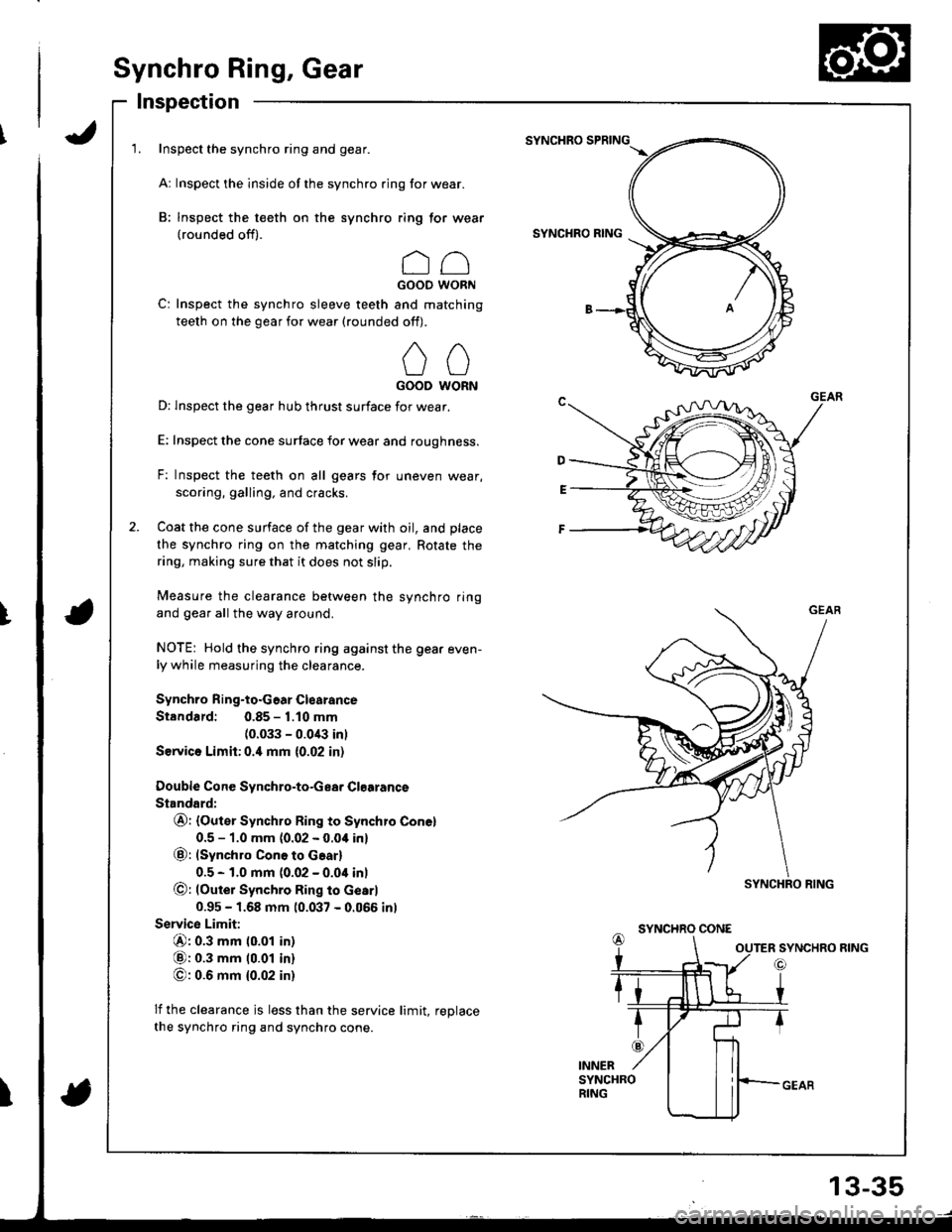
Synchro Ring, Gear
Inspection
1. Inspect the synchro ring and gear.
Ar Inspect the inside of the synchro ring for wear.
B: Inspect the teeth on the synchro ring tor wear(rounded off).
ccGOOD WORN
C: Inspect the synchro sleeve teeth and matching
teeth on the gear for wear (rounded off).
00GOOD WORN
D: lnspect the gear hub thrust surface for wear.
E: Inspect the cone surtace for wear and roughness.
F: Inspect the teeth on all gears for uneven wear,
scoring, galling. and cracks.
Coat the cone surface of the gear with oil, and place
the synchro ring on the matching gear, Rotate the
ring, making sure that it does not slip.
Measure the clearance between the synchro ring
and gear all the way around.
NOTE: Hold the synchro ring against the gear even-ly while measuring the clearance.
Synchro Ring-to.Goar Clearance
Standard: 0.85 - 1.10 mm
(0.033 - 0.0/B inl
Service Limh:0.4 mm {0.02 in)
Double Cone Svnchro-to-Gea. Clgarance
Standard:
@r (Outer Synchro Ring to Synchro Conel
0.5 - 1.0 mm {0.02 - 0.04 in}
@: (synchro ConG to Gear)
0.5 - 1.0 mm (0.02 - 0.04 inl
@: lOute; Synchro Ring to Gearl
0.95 - 1.68 mm 10.037 - 0.066 inl
Servic€ Limit:
@: 0.3 mm (0.01 in)
@: 0.3 mm 10.01 in)
O: 0.6 mm {0.02 in}
lf the clearance js less than the service limit, reDlace
the synchro ring and synchro cone.
SYNCHRO SPRING
SYNCHRO RING
SYNCHRO CONE
I
SYNCHRO RING
13-35
Page 419 of 1681
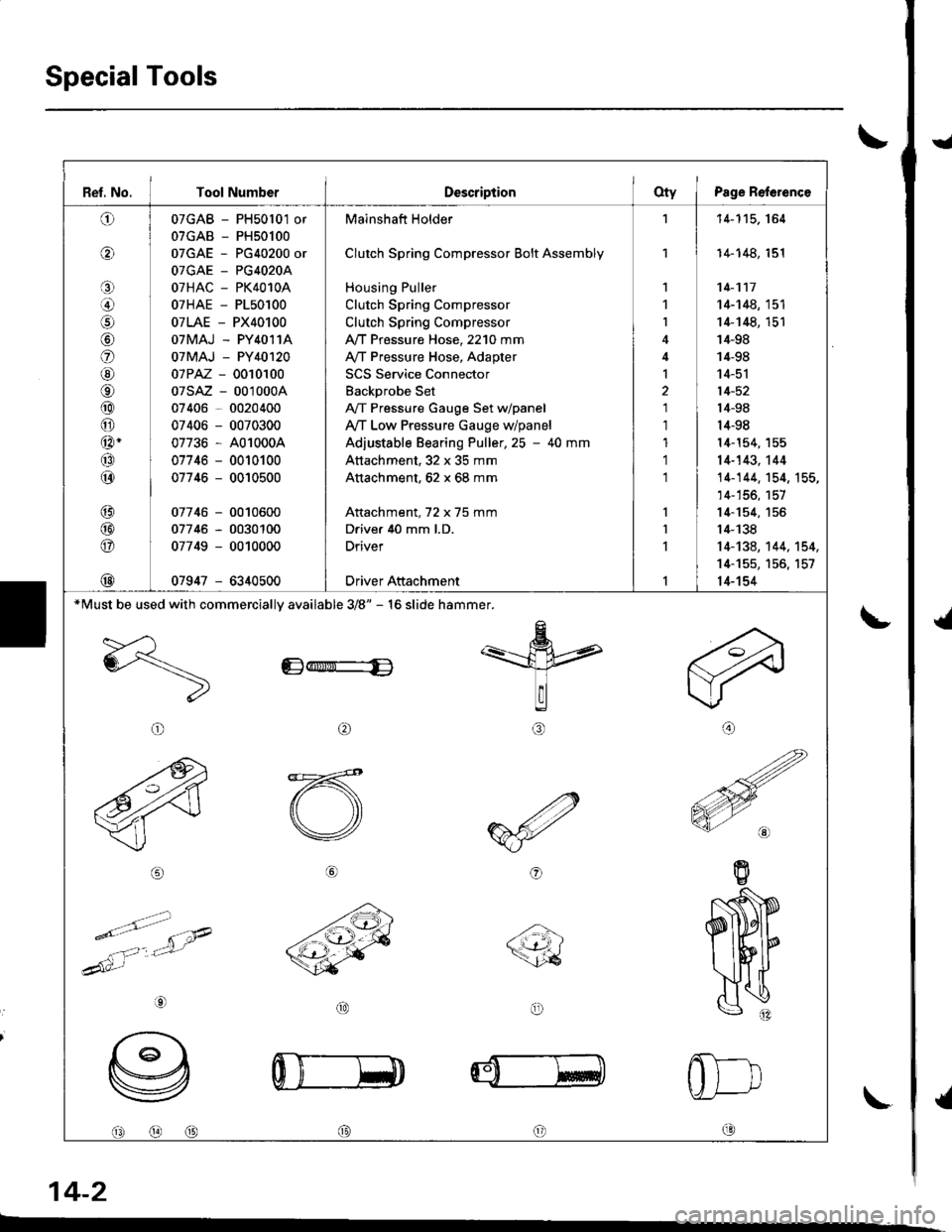
Special Tools
t
{
{
I
\-
\
14-2
Ref. No. I Tool NumberDescriptionOty I Psge Reference
o
o
o
lol
o
@
o
@
@
@-
@
@
@
@
@
@
07GAB - PH50l01 or
07GAB - PH50100
07GAE - PG40200 or
OTGAE _ PG4O2OA
07HAC - PK4010A
07HAE - P150100
07LAE - PX40100
OTMAJ - PY4O11A
07MAJ - PY40120
07PAZ - 0010100
07sAz - 001000A
07406 - 0020400
07406 - 0070300
07736 - A01000A
07746 - 0010100
07746 - 0010500
07746 - 0010600
07746 - 0030100
07749 - 0010000
07947 - 6340500
Mainshaft Holder
Clutch Spring Compressor Bolt Assembly
Housing Puller
Clutch Spring Compressor
Clutch Spring Compressor
,VT Pressure Hose, 2210 mm
A/T Pressure Hose, Adapter
SCS Service Connector
Backprobe Set
A,/T Pressure Gauge Set dpanel
Ay'T Low Pressure Gauge w/panel
Adjustable Bearing Puller,25 - 40 mm
Attachment, 32 x 35 mm
Attachment, 62 x 68 mm
Attachment, 72 x 75 mm
Drive. 40 mm l.D.
Driver
Driver Attachment
1
1
I
I
1
1
1'l
'l
'11-115. 164
14-148, 151
14-117
14-148, 151
14-148, 151'14-98
14-98
14-51
14-52
l4-98
14-98
l4-154, 155
14-143,'t44
14-144. 154, 155,
14-156, 157
14-154, 155
14-138
14-134, 144, 't54,
14-155, 156, 157
14-154
*Must be used with commerciallv available 3/8" - 16 slide hammer.
Edr$ri"-E
arl
@o
@@@c0
Page 466 of 1681
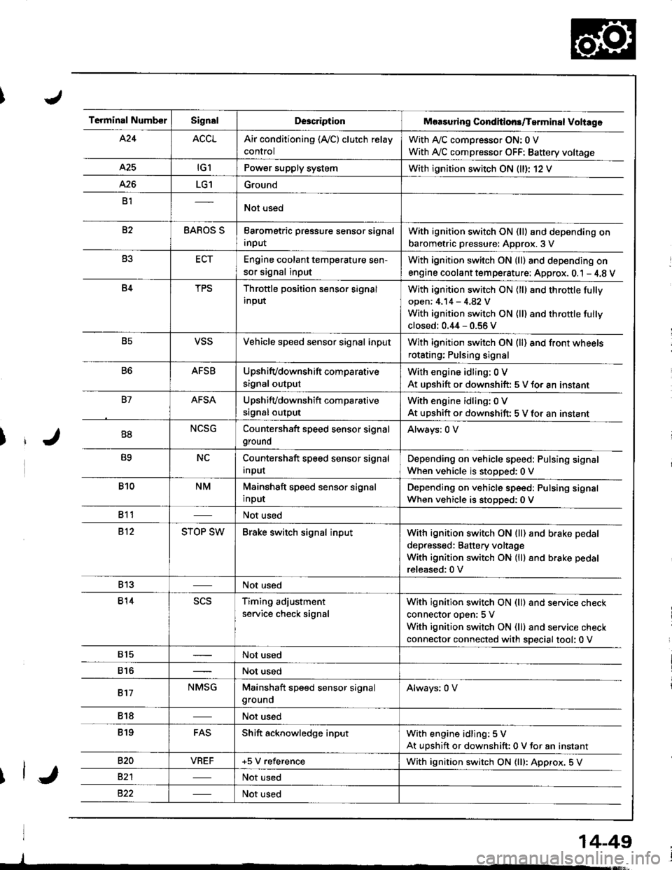
Terminal NumberSignalDescriptionMaasuring Conditlons/Tarminal Voliage
424ACCLAir conditioning (Ay'C) clutch relay
control
With A,/C comDressor ON: 0 V
With Ay'C compressor OFF: Battery voltage
A25tG1Power supply systemWith ignition switch ON (ll)r 12 V
426LG1Ground
B1Not used
82BAROS SBarometric pressure sensor signal
input
With ignition switch ON (ll) and depending on
barometric pressure: Approx. 3 V
B3ECTEngine coolant temperature sen-
sor signal input
With ignition switch ON (ll) and depending on
engine coolant tem perature: Approx. 0.1 - 4.8 V
B4TPSThrottle position sensor signal
input
With ignition switch ON (ll) 8nd throttle fully
open: 4.14 - 4.82 V
With ignition switch ON (ll) and throttle fully
closed: 0.44 - 0.56 V
B5VSSVehicle speed sensor signal inputWith ignition switch ON (ll) and front wheels
rotating; Pulsing signal
B6AFSBUpshifvdownshift comparative
signal output
With engine idling: 0 V
At uDshift or downshift: 5 V for an instant
B7AFSAUpshifvdownshift com parative
srgnal output
With engine idling: 0 V
At upshift or downshift: 5 V for an instant
B8NCSGCountershaft speed sensor signal
ground
Always: 0 V
B9NCCountershaft speed sensor signal
Input
Depending on vehicle speed: Pulsing signal
When vehicle is stopped:0 V
B10NMMainshaft speed sensor signal
input
Depending on vehicle speed: Pulsing signal
When vehicle is stoDoed: 0 V
811Not used
812STOP SWBrake switch signal inputWith ignition switch ON {ll) and b.ake pedal
depressed: Battery voltage
With ignition switch ON (lll and brake pedal
released:0 V
813Not used
814scsTiming adjustment
service check signal
With ignition switch ON (ll) and service check
connector oDen:5 V
With ignition switch ON (ll) and service check
connector connected with special tool: 0 V
815Not used
816Not used
817NMSGMainshaft speed sensor signalgroundAlways: 0 V
818Not used
819FASShift acknowledge inputWith engine idling: 5 V
At upshift or downshift: 0 V for an instant
820VBEF+5 V referenceWith ignition switch ON {lll: Approx. 5 V
82'lNot used
Not used
14-49
Page 468 of 1681
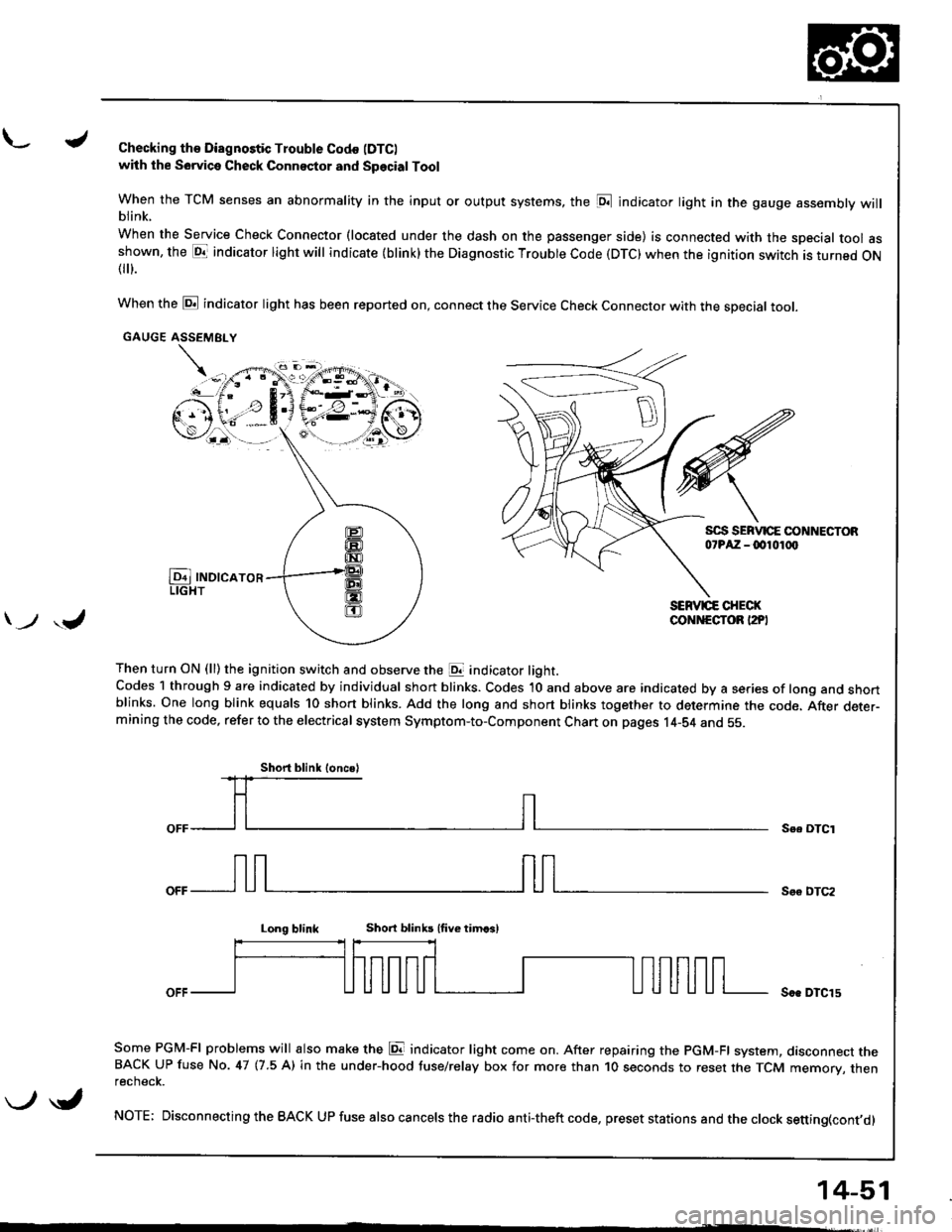
L./Checking th€ Diagnostic Trouble Codo (DTC)
with the Sowica Check Connector and Special Tool
When the TCM senses an abnormality in the input or output systems, the [D;l indicator light in the gauge assembly willblink.
When the Service Check Connector (located under the dash on the passenger side) is connected with the special tool asshown, the E1T indicator light will indicate (blink) the Diagnostic Troubte Code (DTC) when the ignition switch is turned ON{
}.
When the @ indicator light has been reported on, connect the Service Check Connector with the special toot.
GAUGE ASSEMEI.Y
Then turn ON (ll) the ignition switch and observe the E indicator light.Codes 1 through 9 are indicated by individual short blinks. Codes 1O and above are indicated by a series of long and shortblinks. One long blink equals 10 short blinks. Add the long and short blinks together to determine the code. After deter-mining the code, refer to the electrical system Symptom-to-Component Chart on pages 14-S4 and 55.
\-F;ii^r
) ,J
Se. OTCI
Soo DTC2
Long blinkShort blinb lfive timcsl
Soe DTCl5
Some PGM-FI problems will also make the E indicator light come on. After repairing the PGM-FI system, dasconnect theBACK UP fuse No. 47 (7.5 A) in the under-hood tuse/relay box for more than 1O seconds to reset the TCM memory, thenrecnecK.
NOTE; Disconnecting the BACK UP fuse also cancels the radio anti-theft code, preset stations and the clock setting(cont,d)
Short blink loncsl
\-/ \i,
14-51