torque HONDA INTEGRA 1998 4.G User Guide
[x] Cancel search | Manufacturer: HONDA, Model Year: 1998, Model line: INTEGRA, Model: HONDA INTEGRA 1998 4.GPages: 1681, PDF Size: 54.22 MB
Page 182 of 1681
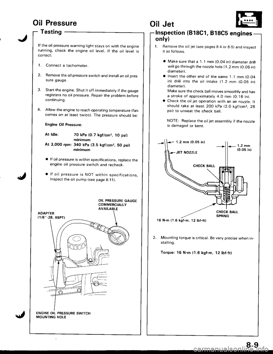
Oil Pressure
Testing
lf the oil pressure warning light stays on with the enginerunning, check the engine oil level. It the oil level iscorrect:
Connect a tachometer.
Remove the oil pressure switch and install an oil pressure gauge.
Start the engine. Shut it off immediately if the gaugeregasters no oil pressure. Repair the problem beforecontinuing.
Allow the engine to reach operating temperature (fan
comes on at least twicel. The pressure should be:
Engine Oil Pressure:
At ldle: 70 kPa {O.7 kgficmr, tO psil
minimum
At 3,OOO rpm: 34O kPa (3.5 kgf/cmr, 50 psil
minimum
a lf oilpressure is within specifications, replace theengine oil pressure switch and recheck.
a lf oil pressure is NOT within specifications,rnspect the oil pump (see page g-11).
l�
2.
Oil Jet
lnspection(818C1, 818C5 engines
only)
1. Remove the oil jet (see pages 8 4 or 8 5) and inspectit as follows.
a Make sure rhat a 1 .1 mm (O.04 in) diameter drillwillgo through the nozzle hole fl.2 mm (O.O5 in)diameter).
a Insert the other end of the same 1 .1 mm {0.O4in) drill into the oit intake (1.2 mm (0.05 in)diameter).
Make sure the check ball moves smoothly and hasa stroke of approximately 4.0 mm (O.16 in).a Check the oil jet operation with an air nozzle. ltshould take at least 2OO kPa 12.O kg|lcm2, 2gpsi) to unseat the check ball.
NOTE: Replace the oiljet assembly if the nozzleis damaged or bent.
2. Mounting torque is critical. Be very precise when in-stalling.
Torque: 16 N.m (1.6 kgf.m, 12 lbf.ftl
1.2 mm (0.05 inl
16 N.m {1.6 kgf'm, 12 lbf.ftl
8-9
Page 254 of 1681
3.Fuel Cut-off Control
. Du ring dece leration with the th rottle va lve closed, cu rrent to the fuel injectors is cutoffto improvefuel economyat
speeds over following rpm:. B'1881 engine: 970 rpm {Canada model: 1.050 rpm). B18C1 engine:970 rpm {Canada model: 1.050 rpm). 818C5 engine: 1,300 rpm (Canada model: 1,400 rpm)
. Fuel cut-off action also takes place when engine speed exceeds 7,000 rpm (B'1881 engine), 8.100 rpm (818C1
engine) or 8,600 rpm (818C5 engine), regardless ol the position of the thronle valve, to protect the engine from
over-revving.
A,,/C ComDressor Clutch Relav
When the ECM receives a demand for cooling from the air conditioning system, it delays the compressor from being
energized, and enriches the mixture to assure smooth transition to the A,/C mode.
Evaporative Emission (EVAP) Purge Control Solenoid Valve
When the engine coolanl temperature is above '154'F (68'C) and the air conditioner on. the ECM controls the EVAPpurge control solenoid valve which controls vacuum to the EVAP purge control canister.
Intake Air Eypass (lAB) Control Solenoid Valve*a
When the engine rpm is below 5,750 rpm, rhe IAB control solenoid valve is activated by a signal from the ECM, intake
air flows through the long intake path, then high torque is delivered. At speeds higher than 5,750 rpm, the solenoidvalve is deactivated by the ECM, and intake air flows through the short intake path in order to reduce the resistance in
airflow.
Sell-diagnosis Function lMalfunction Indicator Lamp {MlL)lWhen an abnormality occurs in a signal from a sensor, the ECM supplies ground for the MIL and stores the code in
erasable memory. When the ignition is initially turned on, the ECM supplies ground for the N4lL tor two seconds to
check the MIL bulb condition.
Two Driving Cycle Detection Method
To prevent false indications, the Two Driving Cycle Detection Method is used for the HO2S, fuel metering-related, idle
control system, ECT sensor, TWC and EVAP control system and other self-diagnostic functions, When an abnormality
occurs, the ECM stores it in its memory. When the same abnormality recurs after the ignition switch is turned OFFand ON (ll)again, the ECM informs the driver by lighting the MlL.
However, to ease troubleshooting, this function is cancelled when you shon the service check connector. The MIL will
then blink immediately when an abnormality occurs.
4.
5.
6.
3.
4.
ECM Fail-safe/8ack.up F0nctions
1. Fail-sate Function
When an abnormality occurs in a signal from a sensor, the ECM ignores that signal and assumes a pre-programmed
value for that sensor that allows the enqine to continue to run.
2. Back-uo Function
When an abnormality occurs in the ECM itself, the fuel injectors are controlled by a back-up circuit independent of the
system in order to permit minimal driving.
11-49
Page 339 of 1681
'{[
'll
I
l'
)l
t,t
H
Ili
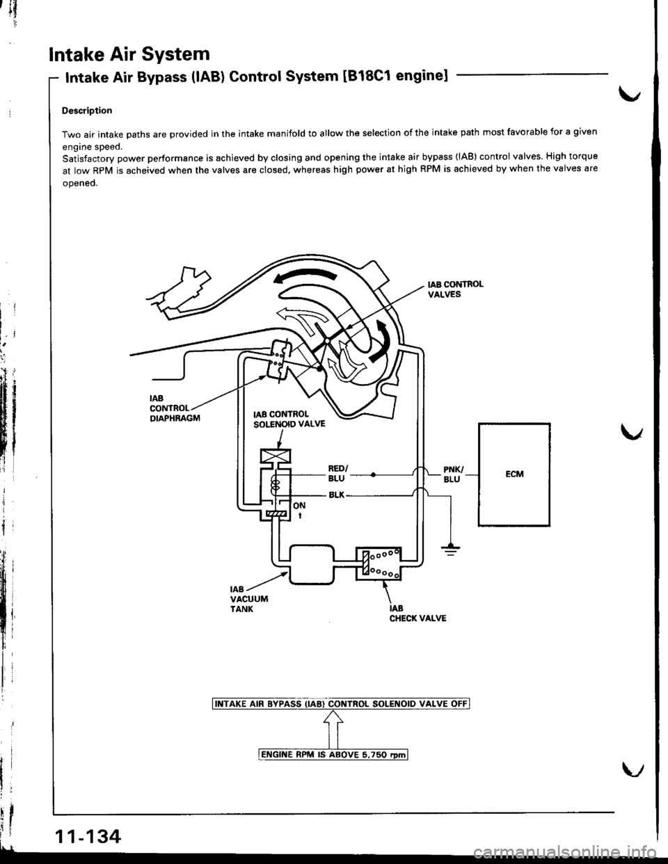
Intake Air System
Intake Air Bypass (lAB) Control System [818C1 enginel
Descriplion
Two air intake oaths are erovided in the intake manifold to allow the selection of the intake path most favofable for a given
engine speed.
Satjsfactory power performance is achieved by closing and opening the intake air bypass (lAB) control valves. High torque
at low RpM is acheived when the valves are closed, whereas high power at high RPM is achieved by when the valves are
opened.
IAB CONTROLVALVES
ECM
illf1l
i 11-134
--_
CHECI( VALVE
Page 367 of 1681
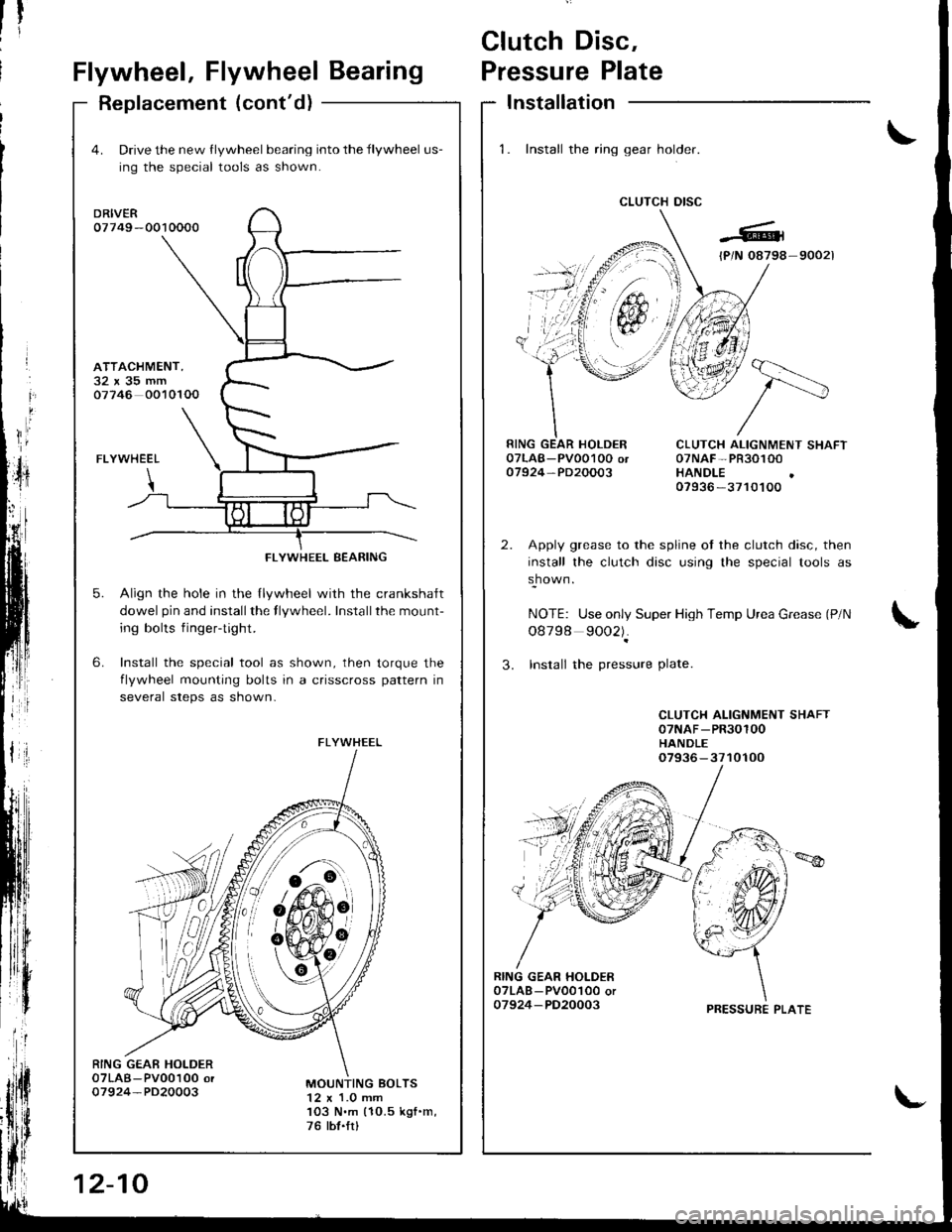
Clutch Disc,
Flywheel, Flywheel BearingPressure Plate
Replacement (cont'd)Installation
1. Install the ring gear holder.
CLUTCH DISC
1tti
CLUTCH ALIGNMENT SHAFT07NAF-PR30100HANDLE07936 -3710100
Apply grease to the spline ot the clutch disc, then
install the clutch disc using the special tools as
shown.
NOTE: Use only Super High Temp Urea Grease (P/N
o8798 9002).
3. Insrall the pressure Plate.
CLUTCH ALIGNMENT SHAFT07NAF-PR30100HANDLE07936-3710100
RING GEAR HOI-DER07LAB - PV001O0 or07924-PD20003
4. Drive the new flywheel bearing into the flywheel us-
ing the special tools as shown.
DRIVER07749 -0010000
FLYWHEEL
Align the hole in the llywheel with the crankshalt
dowel pin and installthe flywheel. Installthe mount-
ing bolts fingertight.
Install the special tool as shown, then torque the
flvwheel mounting bolts in a crisscross pattern in
several steps as shown-
6.
ATTACHMENT,32x35mm07746 0010100
5.
RING GEAE HOLDER07LAB-Pv00100 or07924-PD20003MOUNTING BOLTS12 x 1.0 mm103 N.m (10.5 kgf .m,
76 tbt.frl
FLYWHEEL BEARING
FLYWHEEL
6!-o
&#,oit
12-10
PRESSURE PLATE
Page 368 of 1681
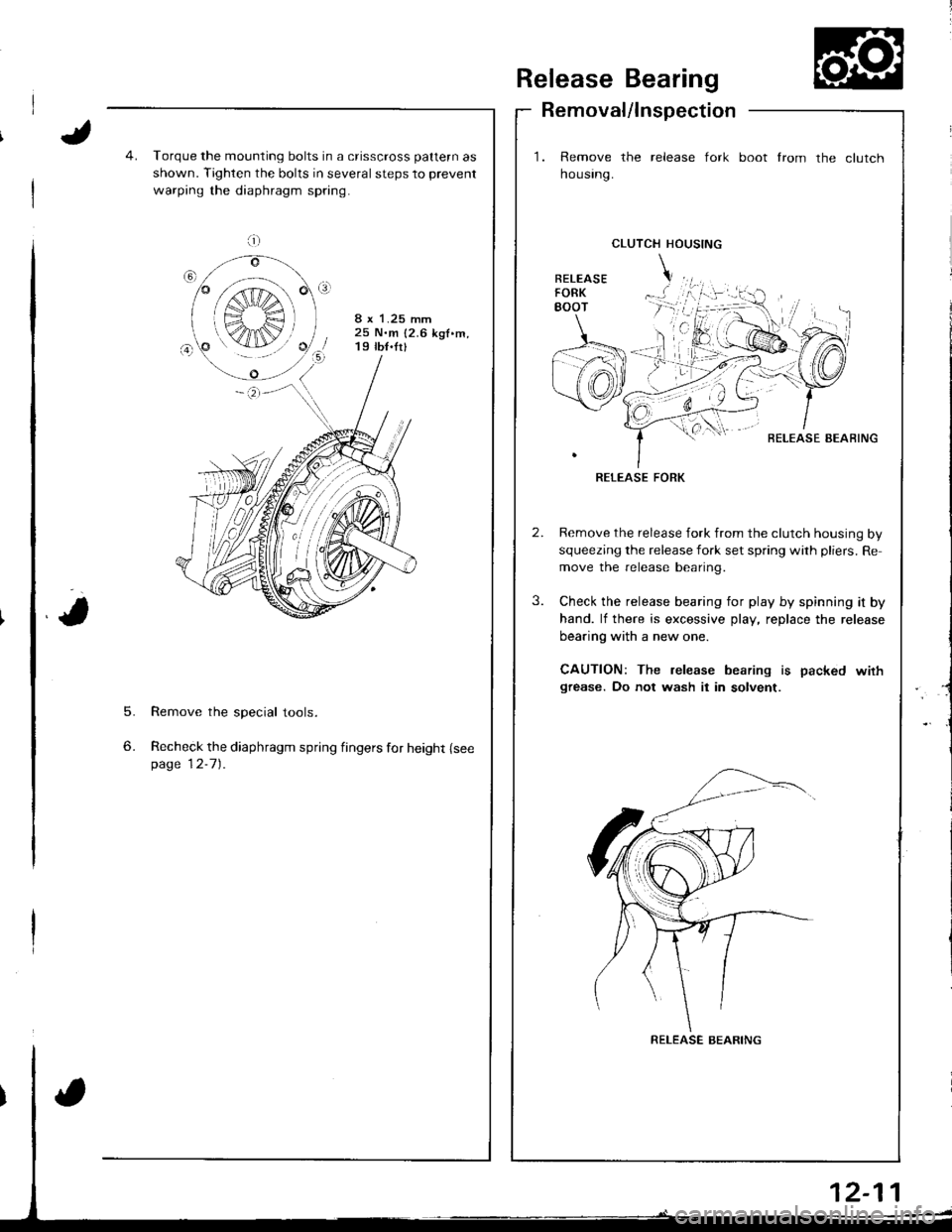
Release Bearing
Removal/lnspection
1. Remove the release fork
housrng.
boot from the clutch
5.
6.
Torque the mounting bolts in a crisscross pattern as
shown. Tighten the bolts in several steps to prevent
warping the diaphragm spring.
8 x 1.25 mm25 N.m {2.6 kgf.m,19 tb{.fr}
Remove the special tools.
Recheck the diaphragm spring fingers for height {seepage 12-7).
CLUTCH HOUSING
BELEASE AEAFING
RELEASE FORK
Remove the release fork from the clutch housing by
squeezing the release fork set spring with pliers. Re
move the release bearing.
Check the release bearing for play by spinning it by
hand. lf there is excessive play, replace the release
bearing with a new one.
CAUTION: The release bearing is packed wirhgrease. Do not wash it in solvent.
a;;;:
S",€ r
K4IN/
RELEASE BEARING
Page 412 of 1681
I
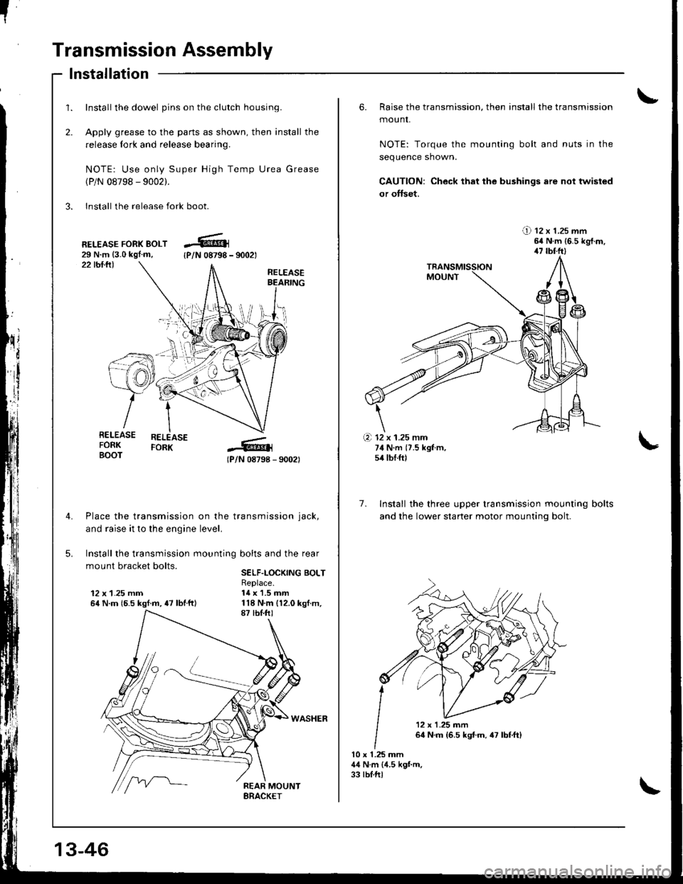
Transmission Assembly
1.
2.
Install the dowel pins on the clutch housing.
Apply grease to the parts as shown, then install the
release fork and release bearing.
NOTE: Use only Super High Temp Urea Grease
(P/N 08798 - 9002).
3. Install the release fork boot.
lnstallation
22 tbl.lll
RELEASE FORK BOLT29 N.m {3.0 kgl.m,{P/N 08798 - 9002t
RELEASEBEAFING
RELEASEFORK
lPlN 08798 - 90021
Place the transmission on the transmission jack,
and raise it to the engine level.
Install the transmission mounting bolts and the rear
mount bracket bolts.SELF.LOCKING BOLT
12 x 1.25 mm64 N.m {6.5 kgf.m, {7 lbtftl
Replace.14 x 1.5 mm
RELEASEFORKBOOT
\i'l-r )i-
.+.i
13-46
6. Raise the transmission, then install the transmission
mounr,
NOTE: Torque the mounting bolt and nuts in the
sequence shown.
CAUTION: Check that the bushings are not twisted
or offset.
!) tz x t.zs mm64 N.m {6.5 kgt.m,47 tbl.ftl
7. Install the three upper transmission mounting
and the lower staner motor mountinq bolt.
bolts
10 x 1.25 mm44 N.m (4.5 kgt m.33 tblftl
(a 12 x 1.25 mm74 N.m {7.5 kgf m,54 tbf.ft)
'12x1.25m�n
64 N.m {6.5 kst.m,47 lbf,ft)
Page 418 of 1681
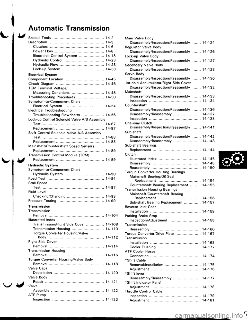
Automatic Transmission
Special Tools ................ '14-2
Descraption .................... 14-3
Clutches ............ ...... 14-6
Power Flow ..,........... 14-8
Electronic Control System ..................... 1 4-1 8
Hydraulic Control ...... 14-23
Hydraulic Flow .........- 14-28
Lock-up System ........ 14-38
Electrical System
Component Location -................................ 1 4-45
Circuit Diagram ............. 14-46
TCM Terminal Voltage/
Measuring Conditions ......,.................... 1 4-48
Troubleshooting Procedures .. . ... ........ ...... ... 14-50
Symptom-to-Component Chart
Electrical System ...... 14-54
Electrical Troubleshooting
Troubleshooting Flowcharts .......... ... ...,.. 14-56
Lock-up Control Solenoid Valve A/B Assembly
Test .................. ...... 14-A7
Replacement ............. 14-a7
Shilt Control Solenoid Valve A/B Assembly
Test .................. ...... '14-88
Replacement .,..,........ 14-88
lvlainshaf t/Countershaft Speed Sensors
Replacement ....-......,. 14-89
Transmission Control Module (TCM)
Replacement ............. 14-89
Hydraulic System
Symptom-to-Component Chart
Hydraulic System ...... 14-90
Road Test ,................... 14-94
Stall Speed
Test .................. ...... 14-97
Fluid Level
Checking/Changing .... 14-98
Pressure Testing ........... 14-99
Transmission
Transmission
Removal ............. ...... 14-10�4
lllustrated lndex
Transmission/Right Side Cover ............... 1 4-1 08
Transmission Housin9 ................,..,....... 1 4-1'1 O
Torque Converter Housing/ValveBody .................. .. 14-112
Right Side Cover
Removal ............. ...... 14-114
Transmission Housing
Removal ............. ...... 14-1 l6
Torque Converter Housing/Valve Body
Removal ............. ...... l4-1 18
Valve Caps
Description ...........-... 14-120
Valve Body
Repair ................ ...... 14-12'l
Valve
Assembly
ATF Pump
Inspeclton
Main Valve Body
Disassembly/lnspection/Reassembly
Regulator Valve Body
Disassembly/lnspection/Reassembly
Lock-up Valve Body
Disassembly/lnspection/Reassembly
Secondary Valve Body
Disassembly/lnspection/Reassembly
Servo Body
....... 14-124
....... 14-126
....... 14-127
....... 14 124
Disassembly/lnspection/Reassembly .......
1st-hold Accumulator/Right Side Cover
Disassembly/lnspection/Reassembly .......
Mainsha{t
14-130
14-132
Disassembly/lnspection/Reassembly ....... 14-133
Inspection ................. 14-134
Countershaft
Disassembly/lnspection/Reassembly,..,.., l4-136
Disassembly/Reassembly ..,...,..,.........,,.. 1 4-1 37
Inspection ......,...,..,... 14-138
One-way Clutch
Disassembly/lnspection/Reassembly ....,.. 14-141
Sub-shaft
Disassembly/lnspection/Reassembly ...,,..'14-142
Disassembly/Reassembly ....................... 1 4- l 43
Sub-shaft Bearings
Replacement ,..,,.,,..,.. 14-144
Clutch
lllustrated Index ................................... I 4-1 45
Disassembly ............. 14-144
Reassembly .............. 14-150
Torque Converter Housing Bearings
Mainshaft Bearing/Oil Seal
Replacement ......... 14-154
Countershaft Bearing Replacement ......... 1 4- 1 55
Transmission Housing Bearings
Mainshaft/Countershaft BearingReplacement ......,.. 14-'156
Sub-shaft Bearing Replacement .,............ 1 4-1 57
Reverse ldler Gear
Installation .........-..... 14-158
Parking Brake Stop
Inspection/Adjustment .......................... 1 4-1 58
Transmission
Reassembly .............. 14-160
Torque Converler/Drive Plate ..............,.,,.,, 1 4-1 67
Transmission
Installation ............... 14-168
Cooler Flushing ......... 14-172
ATF Cooler Hoses
Connection ,..,,,....,,.,, '14-'174
*shift cable
Removal/lnstallation . . .. .... ... .... ... .... .. . ... .. 14-'l75
Adjustment ,..,...,,,,.,, 14-'116*Shilt lever
Disassembly/Reassembly ....................... 1 4-'17 7'Shift Indicator Panel
Adjustment .............. 14-178
\l
)g
Page 420 of 1681
Description
\J
t{
{
14-3
The automatic transmission is a combination of a 3-element torque converter and triple-shalt electronically controlled
automatic transmission which provides 4 speeds forward and 1 speed reverse. The entire unit is positioned in line with
the engrne.
Torque Converter, Gears, and Clutches
The torque converter consists of a pump, turbine, and stator, assembled in sigle unit. The torque converter is connected to
the engine crankshaft so they turn torether as a unit as the engine turns. Around the outside of the torque convener is a
ring gear which meshes with the starter pinion when the engine is being started. The entire torque converter assembly
serves as a flywheel while transmitting power to the transmission mainshaft.
The transmission has three parallel shafts; the mainshaft. the countershaft, and the sub shaft. The mainshaft is in-line with
the engine crankshaft.
The mainshaft includes the 1st, and 2ndl4th clutches,and gear for 3rd, 2nd, 4th, reverse, and 1st. (3rd gear is integral with
the mainshaft, while reverse gear is integral with the 4th gear.)
The countershaft includes the 3rd clutch and gears for 3rd,2nd, 4th, reverse, 1st, and parking. Reverse and 4th gears can
be loched to the countershaft at its center,providing 4th gear or reverse, depending on which way the selector is moved.
The sub-shaft includes the 1st-hold clutch and gears fo 1st and 4th.
The gears on the mainshaft are in constant mesh with those on the countersahft and sub-shaft.When certain combinations
of gears in the transmission are engaged by clutches. power in transmitted from the mainshaft to the countershaft via the
sub-shaft to orovude oil, lo'1. E, E. and E.
Electronic Control
The electronic control svstem consists of the Transmission Control Module (TCM), sensors, and four solenoid valves.
Shilting and lock-up are electronically controlled for comfortable driving under all conditions.
The TCM is located below the dashboard, behind the lelt side kick panel on the driver's side.
Hydraulic Control
The valve bodies include the main valve body, the secondary valve body, the regulator valve body, the serbvo body, and
the lock-up valve body, through the respective separator plates, They are bolted to the torque converter housing,
The main valve body contains the manual valve, the 1-2 shift valve, the 2-3 shitt valve, the Clutch Pressure Control
lCPC) valve, the 4th exhaust valve, the reliel valve, and the ATF pump gears.
The secondary valve body contains the 4-3 kick-down valve, the 3-2 kick-down valve, the 2-3 orifice control valve, the
3-4 shift valve, the orilice control valve, the modulator valve, and the servo control valve.
The regulator valve body contains the pressure regulator valve, the lock-up control valve, the torque converter check
valve, and the cooler check valve.
The servo body contains the servo valve, which is integrated with shift fork shaft, the throttle valve B, and the accumula-
tors.
The lock-up valve body contains the lock-up shift valve and the lock-up timing B valve, and is bolted to the regulator valve
ooqy.
Fluid from the regulator passes through the manual valve to the various control valves.
Shift Control Mechanism
Input to the TCM from various sensors located throughout the car determines which shift control solenoid valve should
be activated. Activating a shitt control solenoid valve changes modulator pressure, causing a shift valve to move. This
pressurizes a line to one ol the clutches, engaging that clutch and its corresponding gear.
Lock-uD Mechanism
In @ position, in 2nd, 3rd and 4th, and @ position in 3rd, pressurized fluid can be drained lrom the back oI the tor-
que converter through a fluid passage, causing the lock-up piston to be held against the torque converter cover. As this
takes place, the mainshaft rotates at the same speed as the engine crankshaft. Together with hydraulic control, the TCM
optimizes the timing of the lock-up mechanism.
The lock-up valves controlthe range of lock-up according to lock-up control solenoid valves A and B, and throttle valve B.
When lock-up control solenoid valves A and B activate, modulator pressure changes. Lock-up control solenoid valves
A and B are mounted on the torque converter housing, and are controlled by the TCM.
(cont'd)
Page 428 of 1681
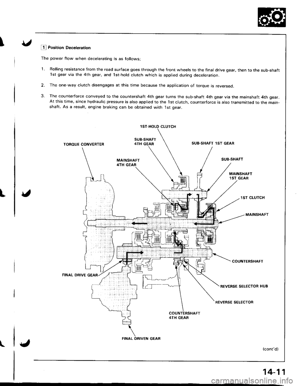
\E Position Deceleration
The power flow when decelerating is as follows;
1. Rolling resistance from the road surface goes through the front wheels to the final drive gear, then to the sub-shaft'lst gear via the 4th gear, and 1st-hold clutch which is applied during decelerarion.
2, The one-way clutch disengages at this time because the application of torque is reversed.
3. The counterforce conveyed to the countershaft 4th gear turns the sub-shaft 4th gear via the mainshaft 4th gear.At this time, since hydraulic pressure is also applied to the 1st clutch, counterforce is also transmitted to the main-shatt. As a.esult. engine braking can be obtained with 1st gear.
CLUTCH
SUB.SHAFT4TH GEARSUB-SHAFT 1ST GEAR
t
TOROUE CONVERTER
FINAL ORIVE
SUB.SHAFT
1ST CLUTCH
MAINSHAFT
COUNTERSHAFT
REVERSE SELECTOR HUB
REVERSE SELECTOR
4TH GEAR
(cont'dl
14-11
\
FINAL ORIVEN GEAR
Page 440 of 1681
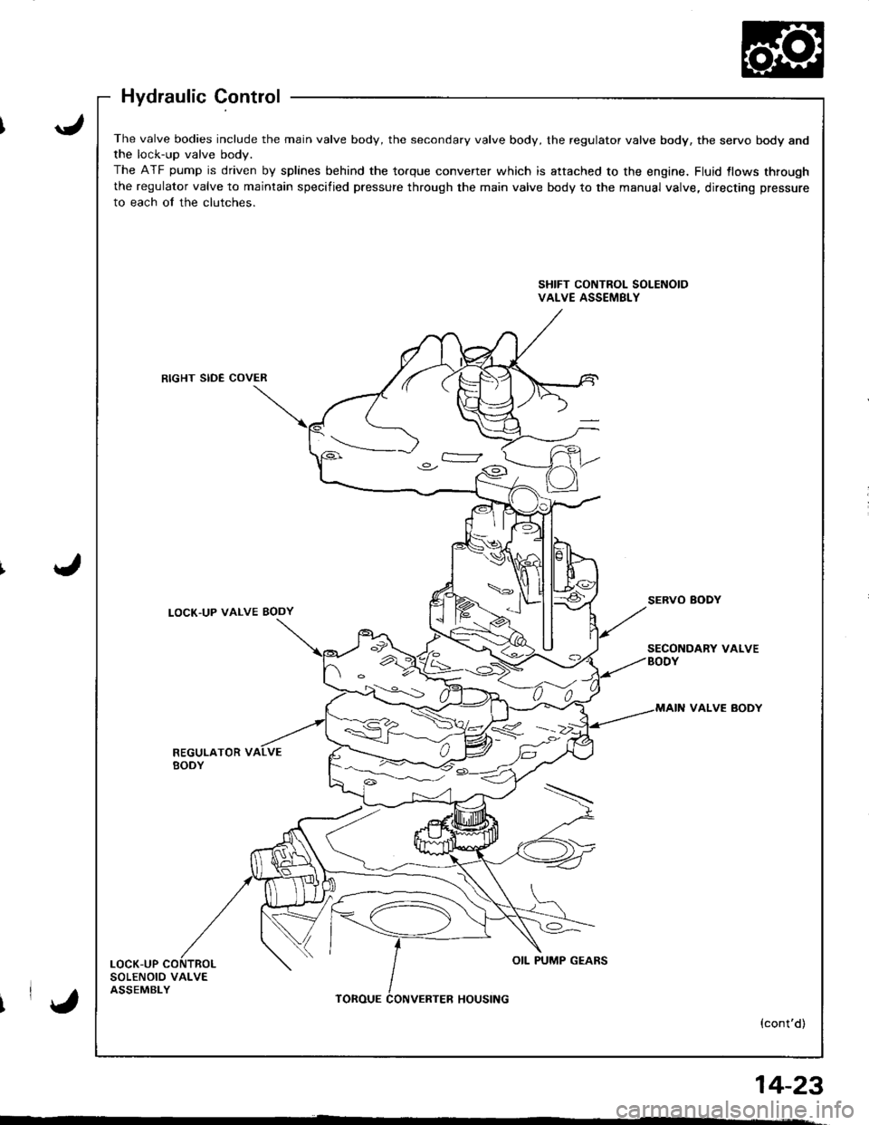
The valve bodies include the main valve body, the secondary valve body, the regulator valve body, the servo body andthe lock-up valve bodv.
The ATF pump is driven by splines behind the torque converter which is attached to the engine, Fluid {lows through
the regulator valve to maintain specified pressure through the main valve body to the manual valve, directing pressure
to each of the clutches.
SHIFT CONTROL SOLENOIDVALVE ASSEMBLY
RIGHT SIDE COVER
LOCK'UP VALVE BODYSERVO BODY
SECONDARY VALVEBODY
VALVE BODY
REGULATOR VBODY
LOCK-UPOIL PUMP GEARS
SOLENOID VALVEASSEMBLYTOROUEHOUSING
{cont'd)
%<->--::/ )C)
IrY,
14_23
'