torque HONDA INTEGRA 1998 4.G Owner's Guide
[x] Cancel search | Manufacturer: HONDA, Model Year: 1998, Model line: INTEGRA, Model: HONDA INTEGRA 1998 4.GPages: 1681, PDF Size: 54.22 MB
Page 458 of 1681
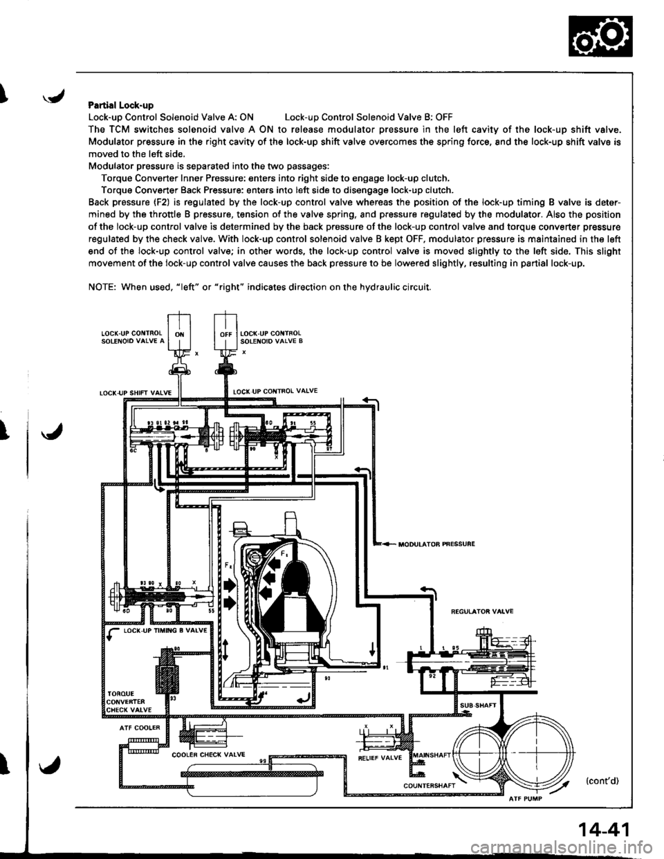
IPartial Lock-up
Lock-uo Control Solenoid Valve A: ONLock-uD Control Solenoid Valve B: OFF
The TCM switches solenoid valve A ON to release modulator Dressure in the left cavity of the lock-up shift valve.
Modulator pressure in the right cavity of the lock-up shift valve overcomes the spring force, 8nd the lock-up shift valve is
moved to the left side,
Modulator pressure is separated into the two passages:
Torque Converter Inner Pressure: enters into right side to engage lock-up clutch,
Torque Converter Back Pressure: enters into left side to disengage lock-up clutch.
Back prassure {F2) is regulated by the lock-up control valve whereas the position of the lock-up timing B valve is deter-
mined by the throttle B pressure, tension of the valve spring, and pressure regulated by the modulator. Also the position
of the lock-up control valve is determined by the back prossure of the lock-up control valve and torque converter pressure
regulated by the check valve. With lock-up control solenoid valve B kept OFF. modulator pressure is maintained in the left
end of the lock-up control valve; in other words, the lock-up control valve is moved slightly to the left side. This slight
movement of the lock-up control valve causes the back pressure to be lowered slightly, resulting in partial lock-up.
NOTE: When used, "|eft" or "right" indicates direction on the hydraulic circuit.
LOCK.UP GO TNOLSOLENOIO VAIVE A
TOCK-UP SHIFT VAIVELOCI( UP COI{TROL VAIVE
T
LOC(,UP IM TG g VALV€
MODULATOB PNESSUFE
14-41
Page 460 of 1681
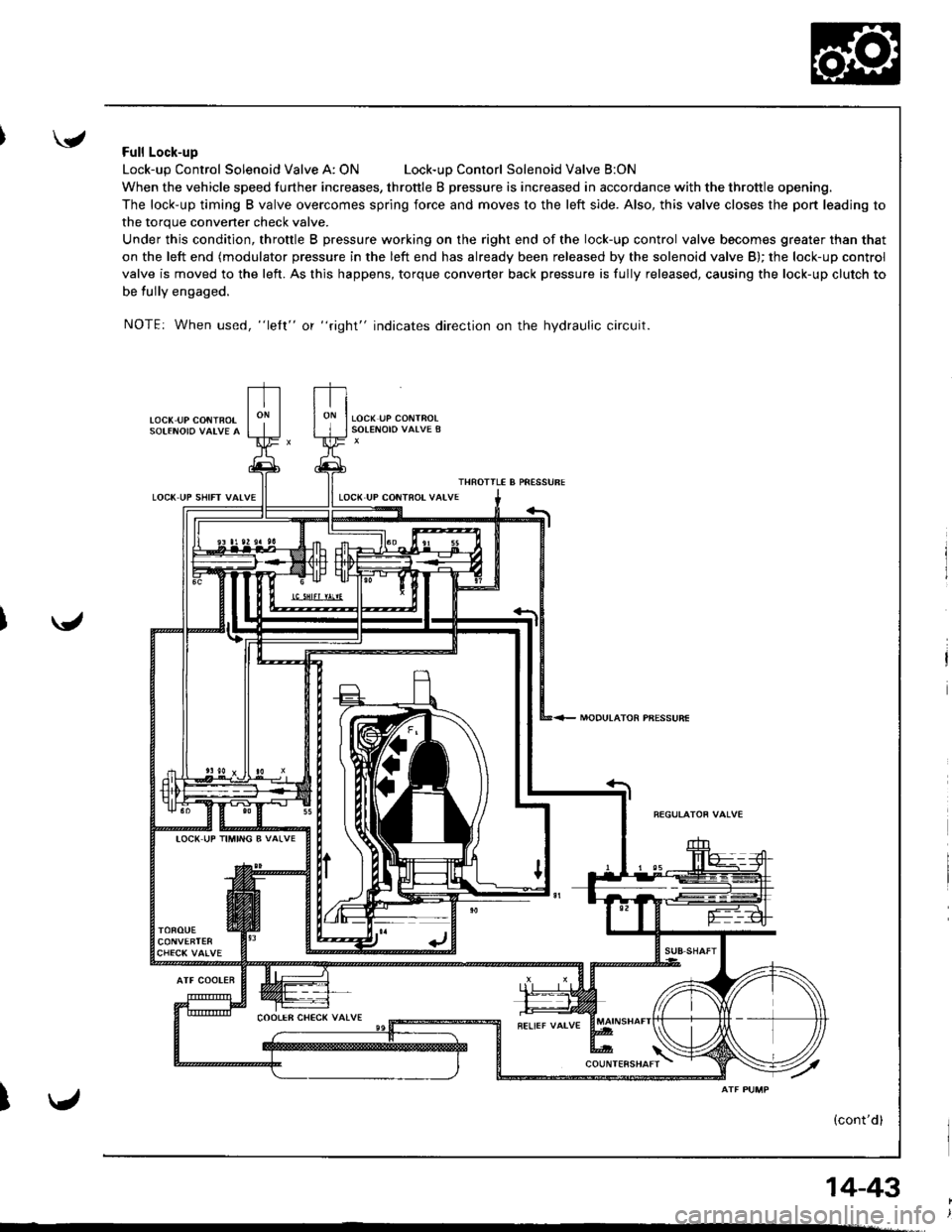
'Full Lock-up
Lock-up Control Solenoid Valve A: ONLock-uD Contorl Solenoid Valve B:ON
When the vehicle speed further increases, throttle B pressure is increased in accordance with the throttle opening.
The lock-up timing B valve overcomes spring force and moves to the left side. Also, this valve closes the port leading to
the torque convener check valve.
Under this condition, throttle B pressure working on the right end of the lock-up control valve becomes greater than that
on the left end (modulator pressure in the left end has already been released by the solenoid valve B); the lock-up control
valve is moved to the left. As this happens, torque converter back pressure is fully released, causing the lock-up clutch to
be tully engaged.
NOTE: When used, "lelt" or "right" indicates direction on the hydraulic circuit.
LOC( UP CONiBOT
LOCK UP SHIFT VAIVE
MODULATOR PBESSURE
ATF COOLER
I
IOC( UP TIMING B VALVE
14-43
Page 461 of 1681
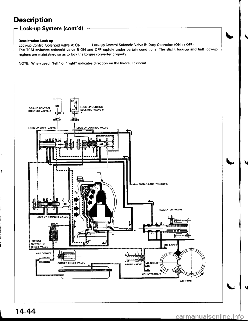
Description
LOCX UP CONTFOLSOLENOIO VAI.VE A
Lock-up System (cont'd)
Deceleration Lock-up
Lock-up Control Solenoid Valve A: ON Lock-up Control Solenoid Valve B: Duty Operation (ON e) OFF)
The TCM switches solenoid valve B ON and OFF rapidly under certain conditions. The slight lock-up and half lock-up
regions are maintained so as to lock the torque converter properly.
NOTE: When used, "|eft" or "right" indicates direction on the hydraulic circuit.
tocK-uP col{TFoLSOTENOID VALV€ B
IOCK-UPCOITTROL VALVE
locK.uP trMrr{G B vAlv€
I 14-44I
\
\
u
Page 508 of 1681
L
\a
\."tl
14-91
J
al
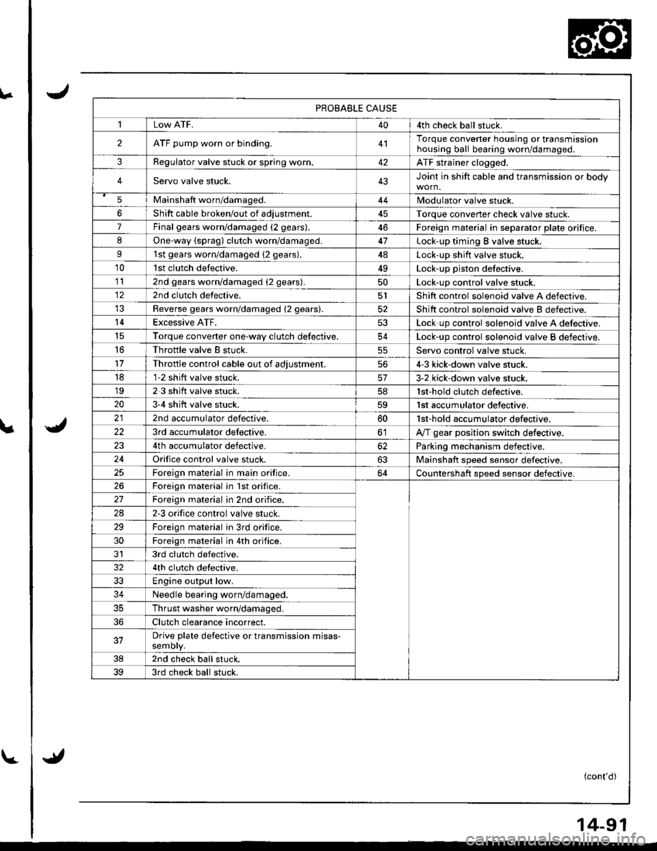
PROBABLE CAUSE
1Low ATF.404th check ball stuck.
2ATF pump worn or binding.4'lTorque converter housing or transmissionhousing ball bearing worn/damageo.
3Regulator valve stuck or spring worr..42ATF strainer clogged.
4Servo valve stuck.43Joint in shift cable and transmission or body
5Mainshaft worn/damaged.44Modulator valve stuck.
6Shift cable broken/out of adiustment45Torque converter check valve stuck.
7Final gears worn/damaged (2 gears).46Foreign material in separator plate orifice.
8One.way {sprag) clutch worn/damaged.47Lock-up timing B valve stuck.
91st gears worn/damaged {2 gears).4ALock-up shift valve stuck.
10lst clutch defective.49Lock-up piston defective.
112nd gears worn/damaged (2 gears).50Lock-up control valve stuck.
122nd clutch defective.5lShift control solenoid valve A defective.
Reverse gears worn/damaged (2 gears).52Shift control solenoid valve B defectrve.
14Excessive ATF.53Lock up control solenoid valve A defective,'t5Torque converter one-wav clutch defective.54Lock-up control solenoid valve B defective.
16Throttle valve B stuck.55Servo control valve stuck.
11Throttle control cable out of adiustment.564-3 kick-down valve stuck.
181-2 shift valve stuck.3-2 kick-down valve stuck.'192 3 shift valve stuck.lst-hold clutch defective.
203-4 shift valve stuck.59'| st accumulator defective.
2nd accumulator defective.60'lst-hold accumulator defective,
223rd accumulator delective,olA,rf gear position switch defective,
4th accumulator defective.62Parking mechanism defective.
24Orifice control valve stuck.63Mainshaft speed sensor defective.
Foreign material in main orifice.64Countershaft speed sensor defective.
26Foreign material in lst orifice.
Foreign material in 2nd orifice.
2A2-3 orifice control valve stuck.
29Foreign material in 3rd orifice.
30Foreign material in 4th orifice.
JI3rd clutch defective.
4th clutch defective.
33Engine output low.
34Needle bearing worn/damaged.
35Thrust washer worn/damaged.
36Clutch clearance incorrect.
37Drive plate defective or transmission misas-semory.
382nd check ball stuck.
393rd check ball stuck.
(cont'd)
Page 509 of 1681
![HONDA INTEGRA 1998 4.G Owners Guide The following symptoms can be caused
by improper repair or assembly
Checkthese items on the
PROBABLE CAUSE DUE TO
IMPROPER REPAIR Llst
Items on the
NOTES List
Vehicle creeps in E] position.R1, R2
Vehi HONDA INTEGRA 1998 4.G Owners Guide The following symptoms can be caused
by improper repair or assembly
Checkthese items on the
PROBABLE CAUSE DUE TO
IMPROPER REPAIR Llst
Items on the
NOTES List
Vehicle creeps in E] position.R1, R2
Vehi](/img/13/6069/w960_6069-508.png)
The following symptoms can be caused
by improper repair or assembly
Checkthese items on the
PROBABLE CAUSE DUE TO
IMPROPER REPAIR Llst
Items on the
NOTES List
Vehicle creeps in E] position.R1, R2
Vehicle does not move in l&l or Lql position.R4
Transmittion locks up in E] position.R3, R12
Excessive drag in transmission.R6K,R
Excessive Vibration, rpm related.R7
Noise with wheels moving only.R5
Msin soal pops out,R8
Various shifting problems.R9, R1O
Harsh upshifts.Rl l
Symptom-to-Gomponent Ghart
Hydraulic System (cont'd)
14-92
\.J
v.4
\/J
PROBABLE CAUSE DUE TO IMPROPER REPAIR
R1lmproper clutch clearance.
R2.lmproper gear clearance.
R3.Parking brake lever installed upside down.
R4.One-way (sprag) clutch installed upside down.
R5.Reverse selector hub installed uoside down.
R6.ATF pump binding.
R7.Torque converter not fully seated in ATF pump.
R8.Main seal improperly installed.
R9.Springs improperly installed.
R10.Valves improperly installed.
R11Ball check valves not installed.
R12.Shift tork bolt not installed.
Page 510 of 1681
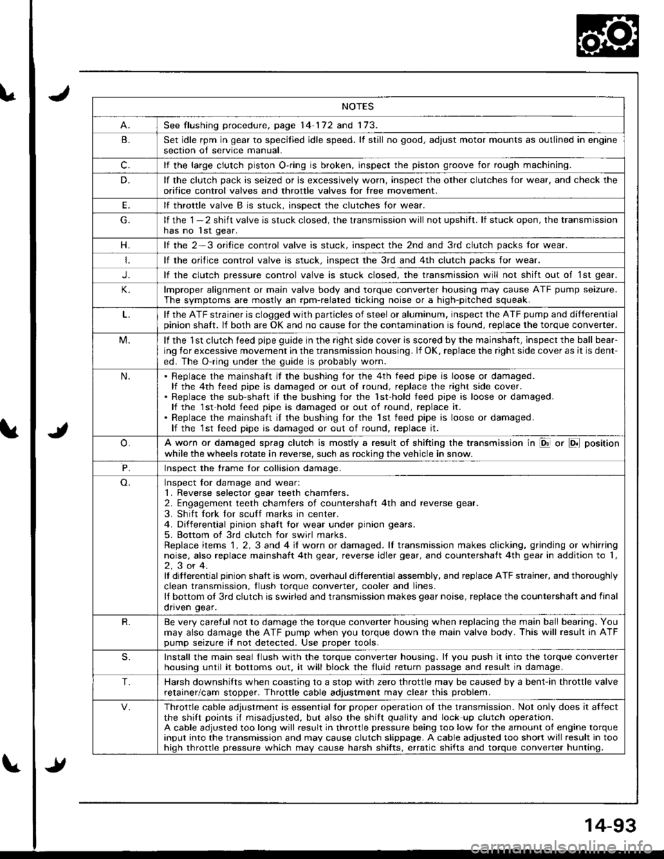
NOTES
See flushing procedure, page 14-172 and 173.
B.Set idle rpm in gear to specilied idle speed. lf still no good, adjust motor mounts as outlined in enginesection of service manual.
c.lf the large clutch piston O-.ing is broken, inspect the piston groove for rough machining.
D.lf the clutch pack is seized or is excessively worn, inspect the other clutches lor wear, and check the
orifice control valves and throttle valves for free mov€ment.
E.lf throttle valve B is stuck. insDect the clutches for wear.
lf the 1 - 2 shift valve is stuck closed, the transmission will not upshitt. lf stuck open, the transmissionhas no lst gear.
H.lf the 2-3 orilice control valve is stuck, inspect the 2nd and 3rd clutch packs for wear.
lf the orifice control valve is stuck. inspect the 3rd and 4th clutch packs for wear.
J.lf the clutch pressure control valve is stuck closed, the transmission will not shift out oI 1st gear.
lmproper alignment or main valve body and torque converter housing may cause ATF pump seizure.
The symptoms are mostly an rpm-related ticking noise or a high-pitched squeak.
lf the ATF strainer is clogged with particles of steel or aluminum, inspect the ATF pump and differentialpinion shaft. lf both are OK and no cause for the contamination is found, replace the torque converter.
M.lf the 1st clutch feed pipe guide in the right side cover is scored by the mainshaft, inspect the ball bear-
ing lor excessive movement in the transmission housing. lf OK, replace the right side cover as it is dent-
ed. The O-ring under the guide is probably worn.
N.Replace the mainshaft if the bushing for the 4th feed pipe is loose or damaged.lf the 4th feed pipe is damaged or out of round, replace the right side cover.Replace the sub-shaft il the bushing for the 1st-hold teed pipe is loose or damaged.lf the 1st-hold teed pipe is damaged or out of round, replace it.
Replace the mainshaft iI the bushing for the lst feed pipe is loose or damaged.lf the 1st leed pipe is damaged or out of round, replace it.
A worn or damaged sprag clutch is mostly a result of shifting the transmission in El or LDll position
while the wheels rotate in reverse, such as rocking the vehicle in snow.
P.Inspect the trame for collision damage.
Inspect lor damage and wear:1. Reverse selector gear teeth chamfers.2. Engagement teeth chamfers of countershaft 4th and reverse gear.
3. Shift fork for scuff marks in center.4. Differential pinion shaft tor wear under pinion gears.
5. Bottom of 3rd clutch for swirl marks.Replace items 1 . 2, 3 and 4 iI worn or damaged. lf transmission makes clicking, grinding or whirringnoise, also replace mainshaft 4th gear, reverse idler gear, and countershatt 4th gear in addition to '1,
2,3or4.It differential pinion shalt is worn, overhaul differential assembly, and replace ATF strainer, and thoroughly
clean transmission, tlush torque conveder, cooler and lines.lf bottom ot 3rd clutch is swirled and transmission makes gear noise, replace the countershaft and final
onven qear.
R.Be very careful not to damage the torque converter housing when replacing the main ball bearing. You
may also damage the ATF pump when you torque down the main valve body. This will result in ATFpump seizure if not detected. Use proper tools.
S.Install the main seal llush with the torque converter housing. lf you push it into the torque converterhousing until it bottoms out. it will block the fluid return passage and result in damage.
T.Harsh downshifts when coasting to a stop with zero throttle may be caused by a bent-in throttle valve
retainer/cam stopper. Throttle cable adjustment may clear this problem.
Throttle cable adjustment is essential tor proper operation ol the transmission. Not only does it affectthe shift points if misadjusted, but also the shift quality and lock up clutch operation.A cable adjusted too long will result in throttle pressure being too low for the amount of engine torqueinput into the transmission and may cause clutch slippage. A cable adjusted too short will result in toohiqh throttle pressure which may cause harsh shifts, erratic shifts and torque converter hunting.
Page 514 of 1681
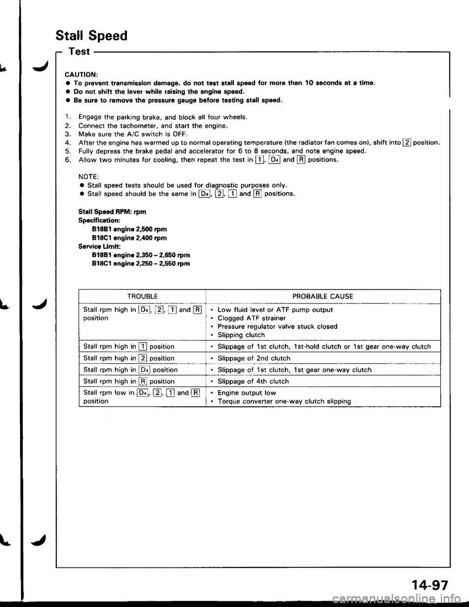
Stall Speed
V
€nt transmission damage, do not tost stall speod for mol€ than
shitt tho lever while raising the engina speed,
10 soconds at a time.
L
CAUTION:
a To prev€nt transmission damage, do not tost stall speod for mol€ than 10 soconds at a time.
a Do not shitt tho lever while raising the engina speed,
a Be suro to remove tho plossule gaugo bolore testing st8ll spe€d.
1. Engage the parking brake. and block all lour wheels.
2. Connect the tachometer, and start the engine,
3. Make sure the A/C switch is OFF.
4. After the engine has warmed up to normal operating temperature {the radiator fan comes on), shift into g position.
5. Fully depress the brake pedal and accelerator for 6 to I seconds. and note engine speed.
6. Allow two minutes for cooling, then repeat the test in [, [Dll and @ oositions.
NOTE:
a Stall speed tests should be used tor diagnostic purposes only.
. Stall speed should be the same in E, tr, tr and @ Fositions.
Stall Speed FPM: rpm
Specification:
Bl88l €ngine 2,5q) rpm
Bl8Cl engine 2.i|{10 .pm
Sorvice Limit:
81881 engins 2,350 - 2,650 rpm
Bl8Ct ongine 2,250 - 2,550 rpm
TROUBLEPROBABLE CAUSE
Stall rpm hish in E, E, I and @position
Low tluid level or ATF pump output
Clogged ATF strainer
Pressure regulator valve stuck closed
Slipping clutch
Stall rpm high in I positionSlippage of 1st clutch, 1st-hold clutch or 1st gear one-way clutch
Stall rpm high in E positionSlippage of 2nd clutch
Stall rpm high in ldnl posirionSlippage of 1st clutch. 1st gear one-way clutch
Stall rpm high in [!l positionSlippage of 4th clutch
Stall rpm low in E, E. I and @position
Engine output low
Torque convener one-way clutch slipping
14-97
Page 516 of 1681
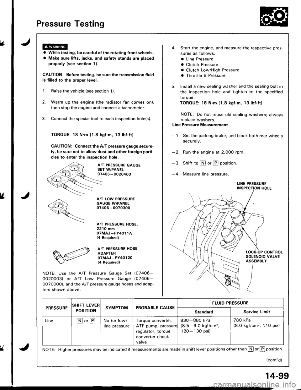
Pressure Testing
a While testing, be careJulot the rotating front wheels.
a Make sule litts, iacks, and safety stands are placed
properly (see section 1).
CAUTION: Befoie testing, be sure the transmission fluid
is filled to the proper level.
'1. Raise the vehicle {see section 'll.
2. Warm up the engine (the radiator fan comes on),
then stop the engine and connect a tachometer.
3. Connect the special tool to each inspection hole(s).
TOROUE: 18 N.m l1-8 kgt.m, 13lbf.ftl
CAUTION: Connect the A/T pressure gauge secure-
ly, be sure not to allow dust and olher foreign pani-
cles to enter the inspection hole.
A/T PRESSURE GAUGESET W/PANEL07406 -0020400
A/T LOW PRESSUREGAUGE W/PANEI.07406-OO70300
A/T PRESSURE HOSE,2210 mmOTMAJ _PY4O1 1A{4 Required}
A/T PRESSURE HOSEADAPTER07MAJ -PY40120
l4 Requiredl
NOTE: Use the A/T Pressure Gauge Set (07406-
OO2O0O3) or A/T Low Pressure Gauge (07406-
OOTOOOO), and the A/T pressure gauge hoses and adap-
ters shown above.
4. Start the engine, and measure the respective pres
sures as follows.
a Line Pressure
a Clutch Pressure
a Clutch Low/High Pressure
a Throttle B Pressure
5. Install a new sealing washer and the sealing bolt in
the inspection hole and tighten to the specified
torque.
TOROUE:18 N.m (1.8 kgf.m, 13lbf.ft)
NOTE: Do not reuse old sealing washers; alwaysreplace washers.
Line Pressure Measurement
-1. Set the parking brake, and block both rear wheels
securely.
-2. Run the engine at 2,000 rpm
3. Shift to S or @ position.
4. lMeasure line pressure.
LINE PRESSUREINSPECTION HOLE
LOCK-UP CONTROLSOLENOID VALVEASSEMBLY
PRESSURESHIFT LEVER
POST ONSYMPTOMPROBABLE CAUSEFLUID PRESSURE
StandardService Limit
LineNo,BNo (or low)
Irne pressure
Torque converter,
ATF pump, pressure
regulator, torque
converter check
830 88o kPa
(8.5 9.O kgf/cm'�,
1 20 130 psi)
78O kPa(8.O kgf/cm'�, 1 10 psi)
NOTE: Higher pressures may be indicated if measurements are made in shitt lever positions other than S or f, position.
{cont'd )
14-99
Page 524 of 1681
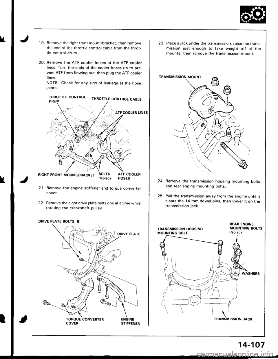
u19.Remove the right front mount/bracket, then remove
the end of the throltle control cable from the throt-
tle control drum.
Remove the ATF cooler hoses at the ATF cooler
lines. Turn the ends of the cooler hoses up to pre-
vent ATF from flowing out, then plug the ATF cooler
lines.
NOTE: Check for any sign ol leakage at the hosejornrs.
THROTTLE CONTROL CABLE
20.
f
RIGHT FRONT MOUNT/BRACKET
21. Remove the engine stiftener and torque converter
cover,
22. Remove the eight drive plate bolts one at a time whilerotating the crankshaft pulley.
EOLTS ATF COOLERReplace. HOSES
ENGINESTIFFENERCOVERTRA
14-107
23. Place a jack under the transmission. raise the trans-mission just enough to take weight off of the
mounts, then remove the transmtssion mount.
TRANSMISSION MOUNT
24. Remove the transmission housing mounting bolts
and rear engine mounting bolts.
25. Pull the transmission away trom the engine until itclears the 14 mm dowel pins, then lower it on thetransmission jack.
REAR ENGINEMOUNTING BOLTSReplace.
WASHERS
MISSION JACK\NS
Page 526 of 1681
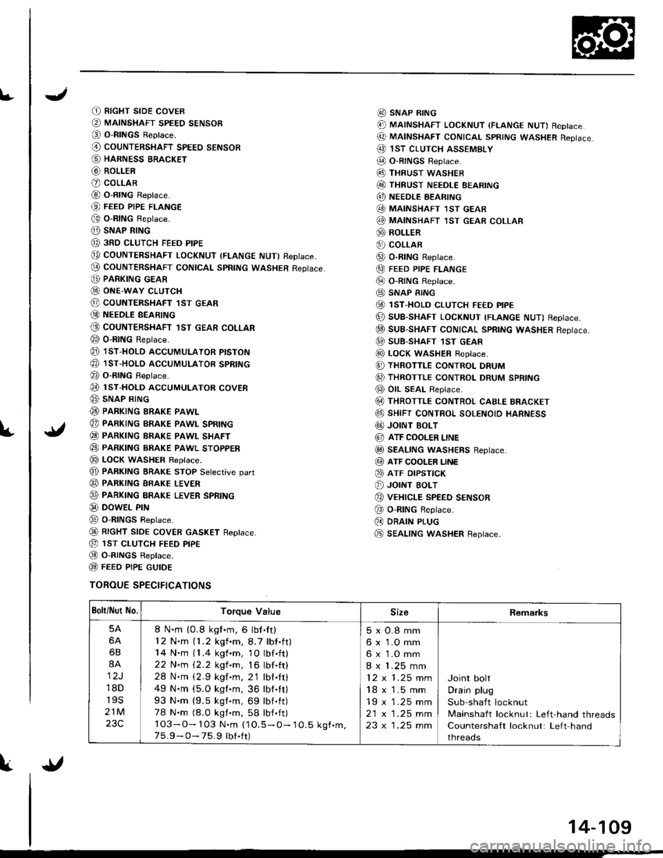
L
(t RtcHT sroE covER
@ MAINSHAFT sPEEo sENsoR(O O-RINGS Reptace.
@ couNTERSHAFT spEEo sENsoR
@ HARNESS BRACKET
@ RoLLER
O coLLAR
@ O-RING Replace.
@ FEEo PIPE FLANGE
@ o-RtNG Reptace.
O) SNAP RING
@ 3RD cLUTcH FEED PIPE
@ COUNTERSHAFT LocKNUT (FLANGE NUT) RepIace,
@ couNTERSHAFT CONtcAL spRtNG wAsHER Reptace.
@ PARKING GEAR
G) ONE-WAY cLUTcH
@ COUNTERSHAFT lST GEAR
@ NEEoLE BEARTNG
@ COUNTERSHAFT 1ST GEAR COLLAR
€0 o-RING Reprace.
@ 1sT-HoLD AccUMULAToR ptsTok
@ 1sr-HoLD AccUMULAToR spRtNG
@ o-RING Reptace.
@ rsr-HoLD AccUMULAToR covER
@ SNAP RING
@ PARKING BRAKE PAWL
@ PARKING BRAKE PAWL SPRING
€0 PARKTNG BRAKE PAWL SHAFT
@ PARKTNG BRAKE pawl sroppER
€0 LOCK WASHEF Replace.
@ PARKTNG BRAKE STOP Setecrive oart
@ PARKING BRAKE LEVER
@ PARKING ERAKE LEVER SPRING
@ DowEL PrN
@ o-RlNGs Reptace.
@ RtcHT StOE COVER GASKET Reptace.
@ 1sr cLUTcH FEED ptpE
@ O-R|NGS Reptace.
@ FEEO P|PE GUTOE
TOROUE SPECIFICATIONS
@ SNAP R|NG
@ MAINSHAFT LocKNUT (FLANGE NUT) Replace
@ MAtNSHAFT coNtcAL spRtNG wAsHER Reptace.
@ 1sT clurcH ASSEMBLY
@ O-RINGS Reptace.(4D THRUST wASHEB
@ THRUST NEEDLE EEARING
@) NEEDLE EEARING
@ MAINSHAFT 1sT GEAB
@ MAINSHAFT ,IsT GEAR coLLAR
@ ROLLER
€) coLLAR
@ o-R|NG Reptace.
@ FEED PIPE FLANGE
@ o-RtNG Reptace.
@ SNAP RING
@ 1sT-HoLD cLUTcH FE€D ptpE
@ SUB-SHAFT LOCKNUT TFLANGE NUT) Reptace.
@ suB-SHAFT CONTCAL SpRtNG WASHER Reptace.
@ SUB-SHAFT 1sT GEAR
@ LocK WASHER Reptace.
@ THRoTTLE coNTRoL DRUM
6, THRoTTLE coNTRoL DRUM SPRING
@ OIL SEAL Replace.
@ THRoTTLE coNTRoL cAELE BRAGKET
@ sHtFT coNTRoL soLENoto HARNESS
G0) JOINT BOLT
@ ATF COOLER LINE
@ SEAL|NG wASHERS Reptace.
@ ATF cooLER LINE
@ ATF DrPsflcK
@ JOINT BoLT
@ vEHrcLE SPEED sENsoR
@ o-RING Reptace.
(, DRAIN PLUG
@ SEAL|NG wasHER Replace.
Bolti Nut No.Torque ValueSizeRemarks
5A
6A
6B
8A
12J
18D
r9s
21M
23C
8 N.m (0.8 kgf.m, 6 lbf'ft)
12 N.m (1.2 kgf.m,8.7 lbf.ft)
14 N.m { 1 .4 kgf .m, 1 0 lbf .ft)
22 N'm 12.2 kgf 'm, 16 lbf .ft)
28 N.m (2.9 kgf.m. 2'1 lbl.It)
49 N.m {5.O kgl.m, 36 lbf.tt)
93 N.m (9.5 kgt.m, 69 lbf.tt)
78 N.m (8.0 kgt.m, 58 lbf .ft)
103-O- 103 N.m (1O.5 - O- 10.5 kgf.m.7 5.9 - O- 75.9 tbt.ft)
5xO.8mm
6 x 1.O mm
6 x 1.O mm
8 x 1.25 mm
12x1.25mm
18 x 1.5 mm
19 x 1.25 mm
2t x |.25 mm
23 x 1.25 mm
Joint bolt
Drain plug
Sub-shaft locknut
Mainshaft locknut: Left-hand threads
Countershaft locknut: Left hand
threads
{l
14-109