light HUMMER H3 2010 Owners Manual
[x] Cancel search | Manufacturer: HUMMER, Model Year: 2010, Model line: H3, Model: HUMMER H3 2010Pages: 410, PDF Size: 2.24 MB
Page 293 of 410
Vehicle Care 10-27
Brake Fluid
The brake master cylinder reservoir
is filled with DOT 3 brake fluid as
indicated on the reservoir cap. See
Engine Compartment Overview
on
page 10‑6for the location of the
reservoir. There are only two reasons why the
brake fluid level in the reservoir
might go down:
.The brake fluid level goes down
because of normal brake lining
wear. When new linings are
installed, the fluid level goes
back up.
.A fluid leak in the brake
hydraulic system can also cause
a low fluid level. Have the brake
hydraulic system fixed, since a
leak means that sooner or later
the brakes will not work well.
Do not top off the brake fluid.
Adding fluid does not correct a leak.
If fluid is added when the linings
are worn, there will be too much
fluid when new brake linings are
installed. Add or remove brake fluid,
as necessary, only when work is
done on the brake hydraulic system.
{WARNING
If too much brake fluid is added, it
can spill on the engine and burn,
if the engine is hot enough. You
or others could be burned, and
the vehicle could be damaged.
Add brake fluid only when work is
done on the brake hydraulic
system.
When the brake fluid falls to a low
level, the brake warning light comes
on. See Brake System Warning
Light on page 5‑14.
Page 299 of 410
Vehicle Care 10-33
Headlamp Aiming
The vehicle may have a visual
optical headlamp aiming system.
The aim has been preset at the
factory and should need no further
adjustment.
However, if the vehicle is damaged
in a crash, the headlamp aim may
be affected and adjustment may be
necessary.
If oncoming vehicles flash their high
beams at you, this may also mean
the vertical aim needs to be
adjusted.
It is recommended that the vehicle
is taken to your dealer for service if
the headlamps need to be re-aimed.
It is possible however, to re-aim the
headlamps as described.The vehicle should be:.Placed so the headlamps are
7.6 m (25 ft) from a light colored
wall or other flat surface.
.On a level surface which is level
all the way to a wall.
.Placed so it is at a right angle to
the wall or other flat surface.
.Clear of any snow, ice, or mud
on it.
.Fully assembled, the tires
properly inflated, and all other
work stopped while headlamp
aiming is being performed.
.Normally loaded with the spare
tire in its original location and a
full tank of fuel and one person
or 75 kg (160 lbs) sitting on the
driver seat.To adjust the vertical aim:
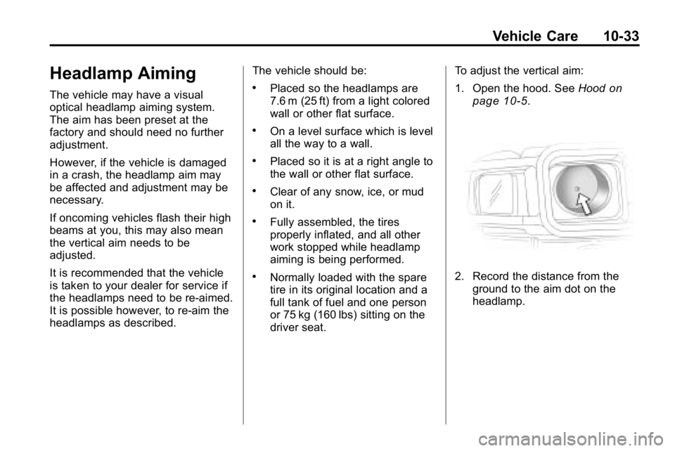
1. Open the hood. See
Hood
on
page 10‑5.
2. Record the distance from the ground to the aim dot on the
headlamp.
Page 300 of 410
10-34 Vehicle Care
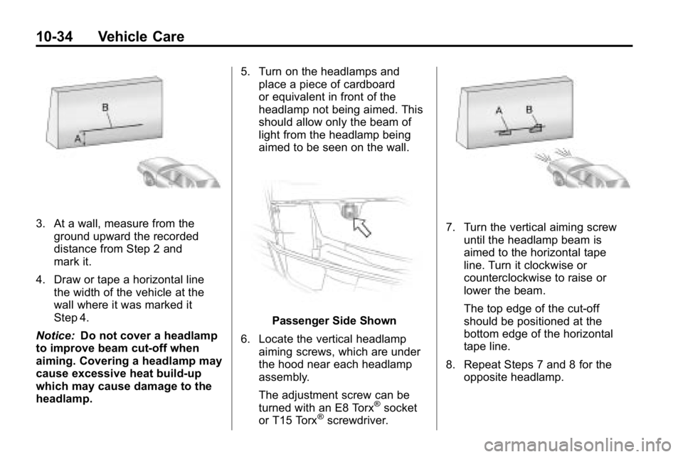
3. At a wall, measure from theground upward the recorded
distance from Step 2 and
mark it.
4. Draw or tape a horizontal line the width of the vehicle at the
wall where it was marked it
Step 4.
Notice: Do not cover a headlamp
to improve beam cut-off when
aiming. Covering a headlamp may
cause excessive heat build-up
which may cause damage to the
headlamp. 5. Turn on the headlamps and
place a piece of cardboard
or equivalent in front of the
headlamp not being aimed. This
should allow only the beam of
light from the headlamp being
aimed to be seen on the wall.
Passenger Side Shown
6. Locate the vertical headlamp aiming screws, which are under
the hood near each headlamp
assembly.
The adjustment screw can be
turned with an E8 Torx
®socket
or T15 Torx®screwdriver.
7. Turn the vertical aiming screw
until the headlamp beam is
aimed to the horizontal tape
line. Turn it clockwise or
counterclockwise to raise or
lower the beam.
The top edge of the cut-off
should be positioned at the
bottom edge of the horizontal
tape line.
8. Repeat Steps 7 and 8 for the opposite headlamp.
Page 305 of 410
Vehicle Care 10-39
Fuses and Circuit
Breakers
The wiring circuits in your vehicle
are protected from short circuits by
a combination of fuses and circuit
breakers. This greatly reduces the
chance of fires caused by electrical
problems.
Look at the silver-colored band
inside the fuse. If the band is broken
or melted, replace the fuse. Be sure
you replace a bad fuse with a new
one of the identical size and rating.
If you ever have a problem on the
road and do not have a spare fuse,
you can borrow one that has the
same amperage. Just pick some
feature of your vehicle that you can
get along without—like the radio
or cigarette lighter —and use its
fuse, if it is the correct amperage.
Replace it as soon as you can.
Engine Compartment
Fuse Block
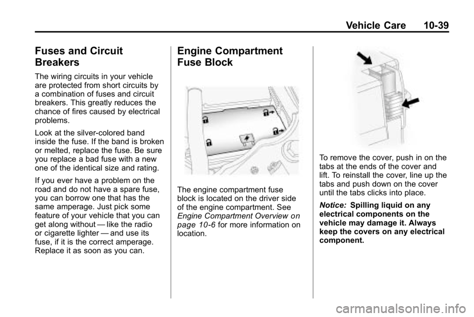
The engine compartment fuse
block is located on the driver side
of the engine compartment. See
Engine Compartment Overview
on
page 10‑6for more information on
location.
To remove the cover, push in on the
tabs at the ends of the cover and
lift. To reinstall the cover, line up the
tabs and push down on the cover
until the tabs clicks into place.
Notice: Spilling liquid on any
electrical components on the
vehicle may damage it. Always
keep the covers on any electrical
component.
Page 308 of 410

10-42 Vehicle Care
FuseUsage
39 Daytime Running
Lamps
40 Passenger Side
Headlamp
41 Driver Side
Headlamp
42 Trailer
Back-Up Lamp
43 Front Park Lamps
44 Air Injection Reactor
(AIR) Solenoid
45 Auxiliary Power 2/
Cigarette Lighter
46 Electronic Throttle
Control
47 Oxygen Sensor
48 Air Conditioning
Clutch
49 Rear Park Lamp
50 Stop Lamp Fuse
Usage
51 Auxiliary Power 1/
Cigarette Lighter
52 StabiliTrak
®,
Antilock Brake
System
53 Power Heated Seat,
Belt Switch
54 Fuel System Control
Module (FSCM)
55 Trailer Parking
Lamps
56 Front Turn Signal,
Hazard Signal,
Courtesy Mirror
57 Power Sunroof
58 Transfer Case
Control Module
Switch
59 Climate Controls
Control Head
60 Back‐Up Lamp
61 Power Seats Fuse Usage
62 Air Injection Reactor
(AIR) Pump
63 Passenger Side
Power Window
64 Antilock Brake
System,
StabiliTrak
®2
Solenoid
67 Antilock Brake
System,
StabiliTrak
®1 Motor
68 Driver Side Power
Window
82 Climate Control Fan
83 Electronic Brake
Controller
84 Trailer B+ Fuse
85 Starter
91 Generator Megafuse
Page 311 of 410
Vehicle Care 10-45
and service description. See the
“Tire Size”illustration later in this
section for more detail.
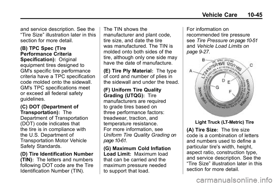
(B) TPC Spec (Tire
Performance Criteria
Specification)
:Original
equipment tires designed to
GM's specific tire performance
criteria have a TPC specification
code molded onto the sidewall.
GM's TPC specifications meet
or exceed all federal safety
guidelines.
(C) DOT (Department of
Transportation)
:The
Department of Transportation
(DOT) code indicates that
the tire is in compliance with
the U.S. Department of
Transportation Motor Vehicle
Safety Standards.
(D) Tire Identification Number
(TIN)
:The letters and numbers
following DOT code are the Tire
Identification Number (TIN). The TIN shows the
manufacturer and plant code,
tire size, and date the tire
was manufactured. The TIN is
molded onto both sides of the
tire, although only one side may
have the date of manufacture.
(E) Tire Ply Material
:The type
of cord and number of plies in
the sidewall and under the tread.
(F) Uniform Tire Quality
Grading (UTQG)
:Tire
manufacturers are required
to grade tires based on
three performance factors:
treadwear, traction, and
temperature resistance.
For more information, see
Uniform Tire Quality Grading
on
page 10‑61
.
(G) Maximum Cold Inflation
Load Limit
:Maximum load
that can be carried and the
maximum pressure needed
to support that load. For information on
recommended tire pressure
see
Tire Pressure
on page 10‑51
and Vehicle Load Limitson
page 9‑27
.
Light Truck (LT-Metric) Tire
(A) Tire Size:The tire size
code is a combination of letters
and numbers used to define a
particular tire's width, height,
aspect ratio, construction type,
and service description. See the
“Tire Size” illustration later in this
section for more detail.
Page 313 of 410
Vehicle Care 10-47
(B) Tire Width:The three‐digit
number indicates the tire section
width in millimeters from
sidewall to sidewall.
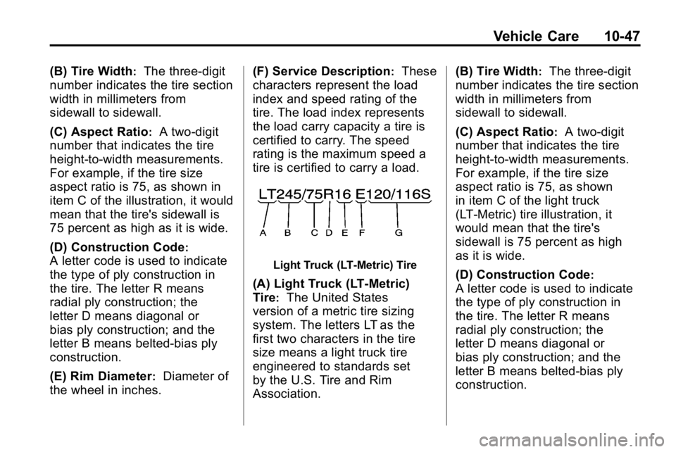
(C) Aspect Ratio
:A two‐digit
number that indicates the tire
height‐to‐width measurements.
For example, if the tire size
aspect ratio is 75, as shown in
item C of the illustration, it would
mean that the tire's sidewall is
75 percent as high as it is wide.
(D) Construction Code
:
A letter code is used to indicate
the type of ply construction in
the tire. The letter R means
radial ply construction; the
letter D means diagonal or
bias ply construction; and the
letter B means belted‐bias ply
construction.
(E) Rim Diameter
:Diameter of
the wheel in inches. (F) Service Description
:These
characters represent the load
index and speed rating of the
tire. The load index represents
the load carry capacity a tire is
certified to carry. The speed
rating is the maximum speed a
tire is certified to carry a load.
Light Truck (LT‐Metric) Tire
(A) Light Truck (LT‐Metric)
Tire
:The United States
version of a metric tire sizing
system. The letters LT as the
first two characters in the tire
size means a light truck tire
engineered to standards set
by the U.S. Tire and Rim
Association. (B) Tire Width
:The three‐digit
number indicates the tire section
width in millimeters from
sidewall to sidewall.
(C) Aspect Ratio
:A two‐digit
number that indicates the tire
height‐to‐width measurements.
For example, if the tire size
aspect ratio is 75, as shown
in item C of the light truck
(LT‐Metric) tire illustration, it
would mean that the tire's
sidewall is 75 percent as high
as it is wide.
(D) Construction Code
:
A letter code is used to indicate
the type of ply construction in
the tire. The letter R means
radial ply construction; the
letter D means diagonal or
bias ply construction; and the
letter B means belted‐bias ply
construction.
Page 315 of 410

Vehicle Care 10-49
DOT Markings:A code
molded into the sidewall of a
tire signifying that the tire is
in compliance with the U.S.
Department of Transportation
(DOT) motor vehicle safety
standards. The DOT code
includes the Tire Identification
Number (TIN), an alphanumeric
designator which can also
identify the tire manufacturer,
production plant, brand, and
date of production.
GVWR
:Gross Vehicle Weight
Rating. See Vehicle Load Limits
on page 9‑27.
GAWR FRT
:Gross Axle
Weight Rating for the front axle.
See Vehicle Load Limits
on
page 9‑27
.
GAWR RR
:Gross Axle
Weight Rating for the rear axle.
See Vehicle Load Limits
on
page 9‑27
. Intended Outboard Sidewall
:
The side of an asymmetrical tire,
that must always face outward
when mounted on a vehicle.
Kilopascal (kPa)
:The metric
unit for air pressure.
Light Truck (LT‐Metric) Tire
:
A tire used on light duty trucks
and some multipurpose
passenger vehicles.
Load Index
:An assigned
number ranging from 1 to 279
that corresponds to the load
carrying capacity of a tire.
Maximum Inflation Pressure
:
The maximum air pressure to
which a cold tire can be inflated.
The maximum air pressure is
molded onto the sidewall.
Maximum Load Rating
:The
load rating for a tire at the
maximum permissible inflation
pressure for that tire. Maximum Loaded Vehicle
Weight
:The sum of curb
weight, accessory weight,
vehicle capacity weight, and
production options weight.
Normal Occupant Weight
:The
number of occupants a vehicle
is designed to seat multiplied by
68 kg (150 lbs). See Vehicle
Load Limits
on page 9‑27.
Occupant Distribution
:
Designated seating positions.
Outward Facing Sidewall
:The
side of an asymmetrical tire that
has a particular side that faces
outward when mounted on a
vehicle. The side of the tire that
contains a whitewall, bears
white lettering, or bears
manufacturer, brand, and/or
model name molding that is
higher or deeper than the same
moldings on the other sidewall
of the tire.
Page 316 of 410

10-50 Vehicle Care
Passenger (P-Metric) Tire:
A tire used on passenger cars
and some light duty trucks and
multipurpose vehicles.
Recommended Inflation
Pressure
:Vehicle
manufacturer's recommended
tire inflation pressure as shown
on the tire placard. See Tire
Pressure
on page 10‑51and
Vehicle Load Limits
on
page 9‑27
.
Radial Ply Tire
:A pneumatic
tire in which the ply cords that
extend to the beads are laid at
90 degrees to the centerline of
the tread.
Rim
:A metal support for a tire
and upon which the tire beads
are seated.
Sidewall
:The portion of a tire
between the tread and the bead. Speed Rating
:An
alphanumeric code assigned
to a tire indicating the maximum
speed at which a tire can
operate.
Traction
:The friction between
the tire and the road surface.
The amount of grip provided.
Tread
:The portion of a tire
that comes into contact with
the road.
Treadwear Indicators
:Narrow
bands, sometimes called wear
bars, that show across the tread
of a tire when only 1.6 mm
(1/16 inch) of tread remains.
See When It Is Time for New
Tires
on page 10‑58. UTQGS (Uniform Tire Quality
Grading Standards)
:A tire
information system that provides
consumers with ratings for a
tire's traction, temperature,
and treadwear. Ratings
are determined by tire
manufacturers using
government testing procedures.
The ratings are molded into
the sidewall of the tire. See
Uniform Tire Quality Grading
on
page 10‑61
.
Vehicle Capacity Weight
:
The number of designated
seating positions multiplied by
68 kg (150 lbs) plus the rated
cargo load. See Vehicle Load
Limits
on page 9‑27.
Vehicle Maximum Load on the
Tire
:Load on an individual tire
due to curb weight, accessory
weight, occupant weight, and
cargo weight.
Page 319 of 410

Vehicle Care 10-53
Please note that the TPMS is
not a substitute for proper tire
maintenance, and it is the driver's
responsibility to maintain correct tire
pressure, even if under‐inflation
has not reached the level to trigger
illumination of the TPMS low tire
pressure telltale.
Your vehicle has also been
equipped with a TPMS malfunction
indicator to indicate when the
system is not operating properly.
The TPMS malfunction indicator is
combined with the low tire pressure
telltale. When the system detects a
malfunction, the telltale will flash for
approximately one minute and then
remain continuously illuminated.
This sequence will continue upon
subsequent vehicle start‐ups as
long as the malfunction exists.
When the malfunction indicator
is illuminated, the system may
not be able to detect or signal
low tire pressure as intended.TPMS malfunctions may occur for
a variety of reasons, including the
installation of replacement or
alternate tires or wheels on the
vehicle that prevent the TPMS
from functioning properly. Always
check the TPMS malfunction
telltale after replacing one or more
tires or wheels on your vehicle to
ensure that the replacement or
alternate tires and wheels allow
the TPMS to continue to function
properly.
See
Tire Pressure Monitor
Operation
on page 10‑53for
additional information.
Federal Communications
Commission (FCC) and
Industry Canada
See Radio Frequency Statementon
page 13‑16for information
regarding Part 15 of the Federal
Communications Commission (FCC)
Rules and RSS-210/211 of Industry
Canada.
Tire Pressure Monitor
Operation
This vehicle may have a Tire
Pressure Monitor System (TPMS).
The TPMS is designed to warn the
driver when a low tire pressure
condition exists. TPMS sensors are
mounted onto each tire and wheel
assembly on the vehicle, excluding
the spare tire. The TPMS sensors
monitor the air pressure in the
vehicle's tires and transmit the tire
pressure readings to a receiver
located in the vehicle.
When a low tire pressure
condition is detected, the TPMS
illuminates the low tire pressure
warning light located on the
instrument panel cluster.