Hyundai Coupe 2002 Service Manual
Manufacturer: HYUNDAI, Model Year: 2002, Model line: Coupe, Model: Hyundai Coupe 2002Pages: 140, PDF Size: 1.45 MB
Page 41 of 140
CONTROLS AND EQUIPMENT1- 33
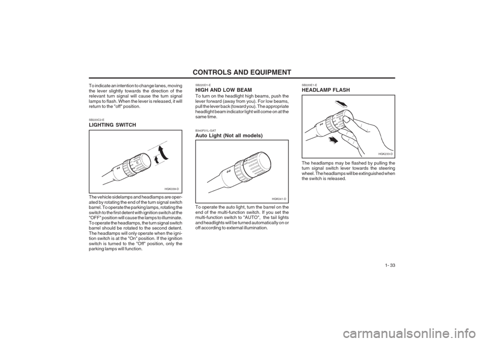
SB220D1-E HIGH AND LOW BEAM To turn on the headlight high beams, push the lever forward (away from you). For low beams, pull the lever back (toward you). The appropriate headlight beam indicator light will come on at the same time.
SB220E1-E HEADLAMP FLASH
SB220C2-E LIGHTING SWITCH The vehicle sidelamps and headlamps are oper- ated by rotating the end of the turn signal switch barrel. To operate the parking lamps, rotating the switch to the first detent with ignition switch at the "OFF" position will cause the lamps to illuminate. To operate the headlamps, the turn signal switch barrel should be rotated to the second detent. The headlamps will only operate when the igni- tion switch is at the "On" position. If the ignition switch is turned to the "Off" position, only the parking lamps will function. The headlamps may be flashed by pulling theturn signal switch lever towards the steering wheel. The headlamps will be extinguished when the switch is released.
To indicate an intention to change lanes, moving the lever slightly towards the direction of the relevant turn signal will cause the turn signal lamps to flash. When the lever is released, it will return to the "off" position.
HGK039-D
To operate the auto light, turn the barrel on the end of the multi-function switch. If you set the multi-function switch to "AUTO", the tail lights and headlights will be turned automatically on or off according to external illumination.
B340F01L-GAT Auto Light (Not all models)
HGK041-D
HGK233-D
Page 42 of 140
CONTROLS AND EQUIPMENT
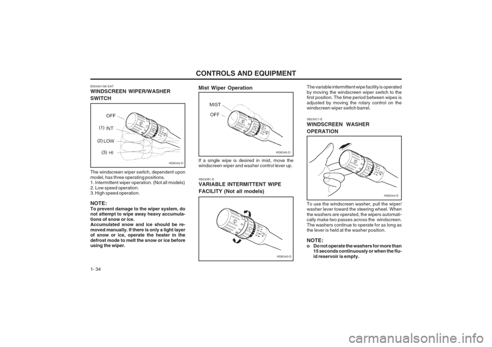
1- 34 SB230B1-E VARIABLE INTERMITTENT WIPE FACILITY (Not all models)
B350A01GK-EAT WINDSCREEN WIPER/WASHER SWITCH The windscreen wiper switch, dependent upon model, has three operating positions. 1. Intermittent wiper operation. (Not all models) 2. Low speed operation. 3. High speed operation. NOTE: To prevent damage to the wiper system, do not attempt to wipe away heavy accumula- tions of snow or ice. Accumulated snow and ice should be re- moved manually. If there is only a light layer of snow or ice, operate the heater in the defrost mode to melt the snow or ice before using the wiper. The variable intermittent wipe facility is operated by moving the windscreen wiper switch to the first position. The time period between wipes is adjusted by moving the rotary control on the windscreen wiper switch barrel. SB230C1-E WINDSCREEN WASHER OPERATION To use the windscreen washer, pull the wiper/ washer lever toward the steering wheel. When the washers are operated, the wipers automati- cally make two passes across the windscreen. The washers continue to operate for as long as the lever is held at the washer position. NOTE:
o Do not operate the washers for more than
15 seconds continuously or when the flu-id reservoir is empty.
HGK042-D
(1)
(2) (3)
HGK043-D
Mist Wiper Operation
HGK045-D
If a single wipe is desired in mist, move the windscreen wiper and washer control lever up.
HGK044-D
Page 43 of 140
CONTROLS AND EQUIPMENT1- 35
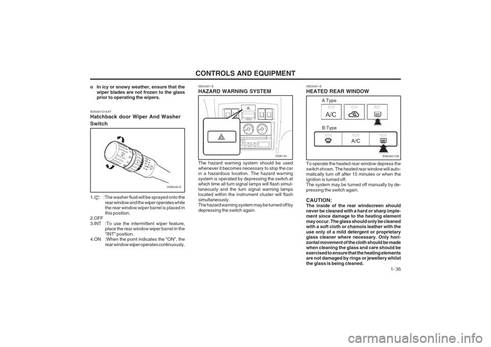
SB250A1-E HEATED REAR WINDOW
SB240A1-EHAZARD WARNING SYSTEM The hazard warning system should be used whenever it becomes necessary to stop the car in a hazardous location. The hazard warning system is operated by depressing the switch at which time all turn signal lamps will flash simul- taneously and the turn signal warning lamps located within the instrument cluster will flash simultaneously. The hazard warning system may be turned off by depressing the switch again. To operate the heated rear window depress theswitch shown. The heated rear window will auto- matically turn off after 15 minutes or when the ignition is turned off. The system may be turned off manually by de- pressing the switch again. CAUTION: The inside of the rear windscreen should never be cleaned with a hard or sharp imple- ment since damage to the heating element may occur. The glass should only be cleaned with a soft cloth or chamois leather with the use only of a mild detergent or proprietary glass cleaner where necessary. Only hori- zontal movement of the cloth should be made when cleaning the glass and care should be exercised to ensure that the heating elements are not damaged by rings or jewellery whilst the glass is being cleaned.
o In icy or snowy weather, ensure that the
wiper blades are not frozen to the glass prior to operating the wipers.
HGK046-D
B350A01O-EAT Hatchback door Wiper And Washer Switch
1. :The washer fluid will be sprayed onto the
rear window and the wiper operates while the rear window wiper barrel is placed in this position.
2.OFF3.INT :To use the intermittent wiper feature, place the rear window wiper barrel in the "INT" position.
4.ON :When the point indicates the "ON", the
rear window wiper operates continuously.
HGK140B380A01GK
A Type
B Type
Page 44 of 140
CONTROLS AND EQUIPMENT
1- 36 SB290A1-F CIGAR LIGHTER
NOTE: The engine must be running for the heated rear window to operate. ZB190A1-A DIGITAL CLOCK SB280A1-EINSTRUMENT PANEL ILLUMINATION CONTROL
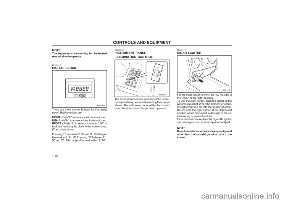
There are three control buttons for the digital clock. Their functions are: HOUR - Push "H" to advance the hour indicated.
MIN - Push "M" to advance the minute indicated.
RESET - Push "R" to reset minutes to ":00" to
facilitate resetting the clock to the correct time. When this is done: Pressing "R" between 10 : 30 and 11 : 29 changes the readout to 11 : 00 Pressing "R" between 11 : 30 and 12 : 29 changes the readout to 12 : 00. The level of illumination intensity of the instru- ment panel may be varied by turning the control shown. The instrument panel will be illuminated when the side or head lamps are in operation.
For the cigar lighter to work, the key must be inthe "ACC" or the "ON" position. To use the cigar lighter, push the lighter all the way into its socket. When the element is heated, the lighter will pop out into the "ready" position. Do not hold the cigar lighter at the depressed position which may result in damage to the ve- hicle wiring or an electrical fire. If it is necessary to replace the cigarette lighter, use only a genuine Hyundai replacement part. NOTE: Do not use electric accessories or equipment other than the Hyundai genuine parts in the socket.
HGK143A
HGK134-D
HGK144-D
Page 45 of 140
CONTROLS AND EQUIPMENT1- 37
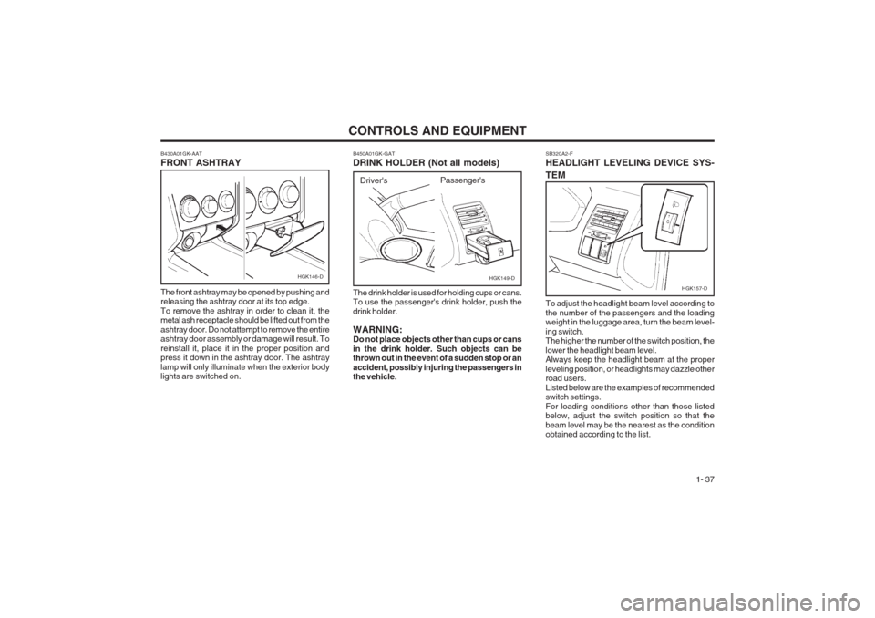
SB320A2-F HEADLIGHT LEVELING DEVICE SYS- TEM
HGK157-D
To adjust the headlight beam level according to the number of the passengers and the loading weight in the luggage area, turn the beam level- ing switch. The higher the number of the switch position, the lower the headlight beam level. Always keep the headlight beam at the proper leveling position, or headlights may dazzle other road users. Listed below are the examples of recommended switch settings. For loading conditions other than those listed below, adjust the switch position so that the beam level may be the nearest as the condition obtained according to the list.
B450A01GK-GAT DRINK HOLDER (Not all models)
HGK149-D
The drink holder is used for holding cups or cans. To use the passenger's drink holder, push the drink holder. WARNING: Do not place objects other than cups or cans in the drink holder. Such objects can be thrown out in the event of a sudden stop or an accident, possibly injuring the passengers in the vehicle. Driver's
Passenger's
B430A01GK-AAT FRONT ASHTRAY The front ashtray may be opened by pushing and releasing the ashtray door at its top edge. To remove the ashtray in order to clean it, the metal ash receptacle should be lifted out from the ashtray door. Do not attempt to remove the entire ashtray door assembly or damage will result. To reinstall it, place it in the proper position and press it down in the ashtray door. The ashtray lamp will only illuminate when the exterior body lights are switched on.HGK146-D
Page 46 of 140
CONTROLS AND EQUIPMENT
1- 38
Loading conditionSwitch position
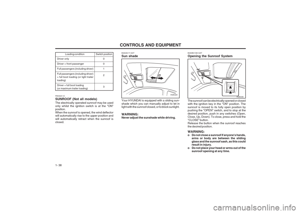
Driver only Driver + front passengerFull passengers (including driver) Full passengers (including driver) + full boot loading (or light trailer loading) Driver + full boot loading (or maximum trailer loading) 0 01 2 3
FB330A1-E SUNROOF (Not all models) The electrically operated sunroof may be used only whilst the ignition switch is at the "ON" position. When the sunroof is opened, the wind deflector will automatically rise to the upper position and will automatically retract when the sunroof is closed. B460A01Y-AAT Sun shadeHGK029
Your HYUNDAI is equipped with a sliding sun- shade which you can manually adjust to let in light with the sunroof closed, or to block sunlight. WARNING: Never adjust the sunshade while driving.
B460B01GK-GAT Opening the Sunroof System
HGK030
The sunroof can be electrically opened or closed with the ignition key in the "ON" position. The sunroof is moved to its fully open position by
pushing the "OPEN" switch, and to stop at the desired position, push in any switches (Open, Close, Up, Down). To close, press and hold the "CLOSE" button. Release the button when the sunroof reaches the desired position. WARNING:
o Do not close a sunroof if anyone's hands, arms or body are between the slidingglass and the sunroof sash, as this could result in injury.
o Do not place your head or arms out of the sunroof opening at any time.
Page 47 of 140
CONTROLS AND EQUIPMENT1- 39
3. Push and turn the wrench counterclockwiseto open or clockwise to close the sunroof.
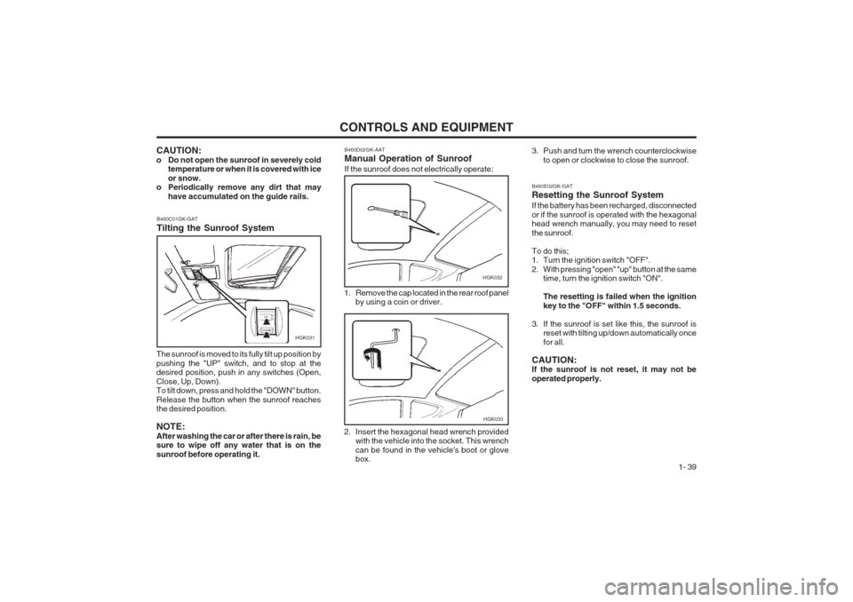
B460D02GK-AAT Manual Operation of Sunroof If the sunroof does not electrically operate:
HGK032
1. Remove the cap located in the rear roof panel by using a coin or driver.
2. Insert the hexagonal head wrench provided with the vehicle into the socket. This wrench can be found in the vehicle's boot or glove box.
HGK033
CAUTION:
o Do not open the sunroof in severely cold temperature or when it is covered with iceor snow.
o Periodically remove any dirt that may
have accumulated on the guide rails.
B460C01GK-GAT Tilting the Sunroof System
HGK031
The sunroof is moved to its fully tilt up position by pushing the "UP" switch, and to stop at the desired position, push in any switches (Open, Close, Up, Down). To tilt down, press and hold the "DOWN" button. Release the button when the sunroof reaches the desired position. NOTE: After washing the car or after there is rain, be sure to wipe off any water that is on the sunroof before operating it.
B460E02GK-GAT Resetting the Sunroof System If the battery has been recharged, disconnected or if the sunroof is operated with the hexagonal head wrench manually, you may need to reset the sunroof. To do this;
1. Turn the ignition switch "OFF".
2. With pressing "open" "up" button at the same time, turn the ignition switch "ON". The resetting is failed when the ignition key to the "OFF" within 1.5 seconds.
3. If the sunroof is set like this, the sunroof is reset with tilting up/down automatically oncefor all.
CAUTION: If the sunroof is not reset, it may not be operated properly.
Page 48 of 140
CONTROLS AND EQUIPMENT
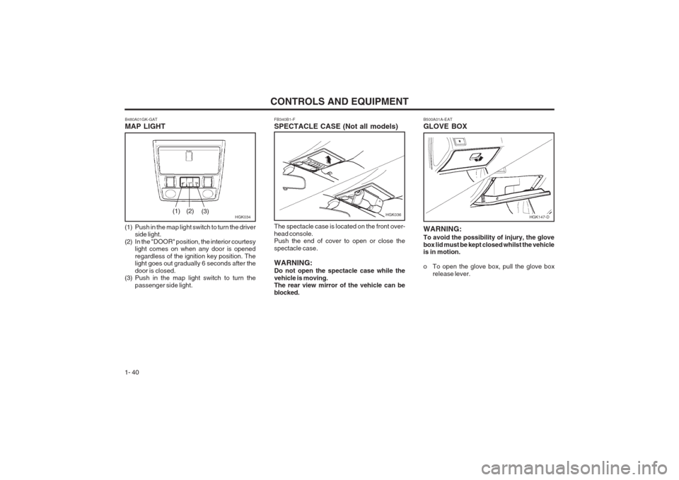
1- 40 FB340B1-F SPECTACLE CASE (Not all models) The spectacle case is located on the front over- head console. Push the end of cover to open or close the spectacle case. WARNING: Do not open the spectacle case while the vehicle is moving. The rear view mirror of the vehicle can be blocked.
B480A01GK-GAT MAP LIGHT
HGK034
(1) Push in the map light switch to turn the driver side light.
(2) In the "DOOR" position, the interior courtesy light comes on when any door is opened regardless of the ignition key position. The light goes out gradually 6 seconds after the door is closed.
(3) Push in the map light switch to turn the
passenger side light.(1) (2) (3)HGK036
B500A01A-EAT GLOVE BOX
WARNING: To avoid the possibility of injury, the glove box lid must be kept closed whilst the vehicle is in motion.
o To open the glove box, pull the glove box
release lever.
HGK147-D
Page 49 of 140
CONTROLS AND EQUIPMENT1- 41
CAUTION:
o Do not operate the switch continuously
for an unnecessary length of time.
o Scraping ice from the mirror face could
cause permanent damage. To remove any ice, use a sponge, soft cloth or approved de-icer.
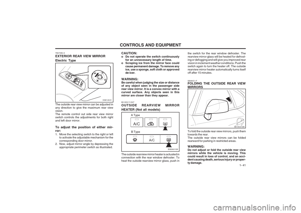
WARNING:Be careful when judging the size or distance of any object seen in the passenger side rear view mirror. It is a convex mirror with a curved surface. Any objects seen in this mirror are closer than they appear. SB360C1-F FOLDING THE OUTSIDE REAR VIEW MIRRORS To fold the outside rear view mirrors, push them towards the rear. The outside rear view mirrors can be folded rearward for parking in restricted areas. WARNING: Do not adjust or fold the outside rear view mirrors while the vehicle is moving. This could result in loss of control, and an acci- dent causing death, serious injury or proper- ty damage.
B510D01Y-EAT OUTSIDE REARVIEW MIRROR HEATER (Not all models) The outside rearview mirror heater is actuated in connection with the rear window defroster. To heat the outside rearview mirror glass, push in the switch for the rear window defroster. Therearview mirror glass will be heated for defrost- ing or defogging and will give you improved rear vision in inclement weather conditions. Push the switch again to turn the heater off. The outside rearview mirror heater automatically turns itself off after 15 minutes.
B510C01GK
B380A01GK
A Type
B Type
HGK128-D
YB270B2-A EXTERIOR REAR VIEW MIRROR Electric Type The outside rear view mirror can be adjusted in any direction to give the maximum rear view vision. The remote control out side rear view mirror switch controls the adjustments for both right and left door mirror. To adjust the position of either mir- ror:
1. Move the selecting switch to the right or left to activate the adjustable mechanism for the corresponding door mirror.
2. Now, adjust mirror angle by depressing the
appropriate perimeter switch as illustrated.
Page 50 of 140
CONTROLS AND EQUIPMENT
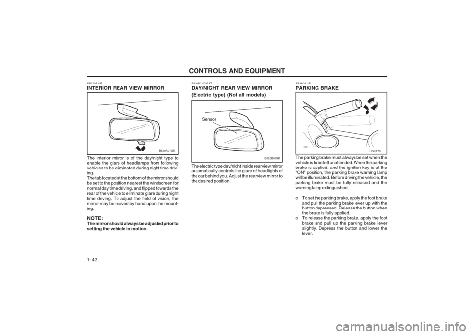
1- 42 SB380A1-E PARKING BRAKE The parking brake must always be set when the vehicle is to be left unattended. When the parking brake is applied, and the ignition key is at the "ON" position, the parking brake warning lamp will be illuminated. Before driving the vehicle, the parking brake must be fully released and the warning lamp extinguished.
o To set the parking brake, apply the foot brake
and pull the parking brake lever up with the button depressed. Release the button when the brake is fully applied.
o To release the parking brake, apply the foot
brake and pull up the parking brake lever slightly. Depress the button and lower the lever.
SB370A1-E INTERIOR REAR VIEW MIRROR The interior mirror is of the day/night type to enable the glare of headlamps from following vehicles to be eliminated during night time driv- ing. The tab located at the bottom of the mirror should be set to the position nearest the windscreen for normal day time driving, and flipped towards the rear of the vehicle to eliminate glare during night time driving. To adjust the field of vision, the mirror may be moved by hand upon the mount- ing. NOTE: The mirror should always be adjusted prior to setting the vehicle in motion.
B520A01GK
B520B01O-GAT DAY/NIGHT REAR VIEW MIRROR (Electric type) (Not all models) The electric type day/night inside rearview mirror automatically controls the glare of headlights of the car behind you. Adjust the rearview mirror to the desired position.
B520B01GK
Sensor
HGK178