Hyundai Coupe 2006 Owner's Manual
Manufacturer: HYUNDAI, Model Year: 2006, Model line: Coupe, Model: Hyundai Coupe 2006Pages: 483, PDF Size: 12.73 MB
Page 311 of 483
1CONTROLS AND EQUIPMENT
44
If the level is insufficient, add the required amount of oil as indicated by the engine oil dipstick. If the lightfails to extinguish when the engine is restarted, do not continue to oper- ate the vehicle.If the oil pressure light illuminates during normal operation and the cause is not an insufficient oil level,or the light fails to illuminate when the ignition is turned "on", contact the nearest Hyundai authorised re-pairer before further operating the vehicle.
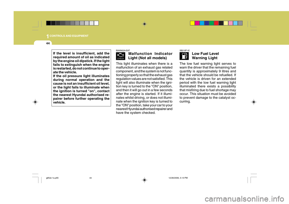
B260N02A-EAT Malfunction Indicator
Light (Not all models)
This light illuminates when there is a malfunction of an exhaust gas relatedcomponent, and the system is not func- tioning properly so that the exhaust gas regulation values are not satisfied. Thislight will also illuminate when the igni- tion key is turned to the "ON" position, and then it will go out in a few secondsafter the engine is started. If it illumi- nates whilst driving, or does not illumi- nate when the ignition key is turned tothe "ON" position, take your car to your nearest Hyundai authorised repairer and have the system checked.SB210P1-E Low Fuel Level Warning Light
The low fuel warning light serves to warn the driver that the remaining fuelquantity is approximately 9 litres and that the vehicle should be refuelled. If the vehicle is driven for an extendedperiod with the low fuel warning light illuminated there exists a possibility that misfiring due to fuel shortage mayoccur. This situation must be avoided to prevent damage to the catalyst oc- curring.
gkfluk-1a.p65 12/26/2006, 5:13 PM
44
Page 312 of 483
1
CONTROLS AND EQUIPMENT
45
!
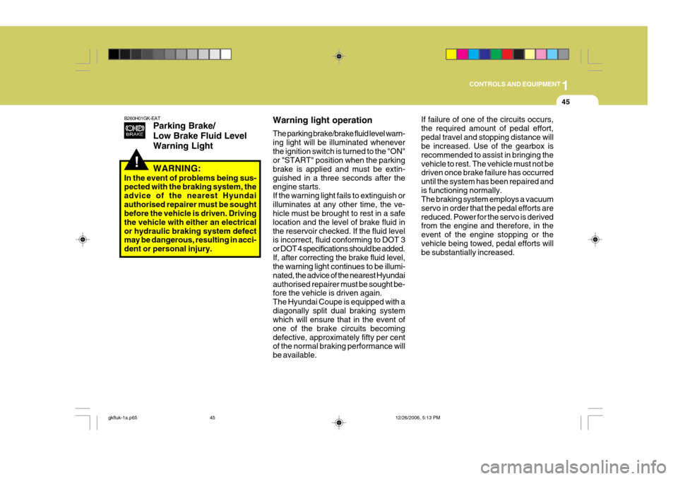
B260H01GK-EAT
Parking Brake/ Low Brake Fluid LevelWarning LightIf failure of one of the circuits occurs, the required amount of pedal effort,pedal travel and stopping distance will be increased. Use of the gearbox is recommended to assist in bringing thevehicle to rest. The vehicle must not be driven once brake failure has occurred until the system has been repaired andis functioning normally. The braking system employs a vacuum servo in order that the pedal efforts arereduced. Power for the servo is derived from the engine and therefore, in the event of the engine stopping or thevehicle being towed, pedal efforts will be substantially increased.
WARNING:
In the event of problems being sus-pected with the braking system, the advice of the nearest Hyundaiauthorised repairer must be sought before the vehicle is driven. Driving the vehicle with either an electricalor hydraulic braking system defect may be dangerous, resulting in acci- dent or personal injury. Warning light operation The parking brake/brake fluid level warn- ing light will be illuminated wheneverthe ignition switch is turned to the "ON" or "START" position when the parking brake is applied and must be extin-guished in a three seconds after the engine starts. If the warning light fails to extinguish orilluminates at any other time, the ve- hicle must be brought to rest in a safe location and the level of brake fluid inthe reservoir checked. If the fluid level is incorrect, fluid conforming
to DOT 3
or DOT 4 specifications should be added. If, after correcting the brake fluid level, the warning light continues to be illumi-
nated, the advice of the nearest Hyundai authorised repairer must be sought be-
fore the vehicle is driven again.The Hyundai Coupe is equipped with adiagonally split dual braking system which will ensure that in the event of one of the brake circuits becomingdefective, approximately fifty per cent of the normal braking performance will be available.
gkfluk-1a.p65 12/26/2006, 5:13 PM
45
Page 313 of 483
1CONTROLS AND EQUIPMENT
46
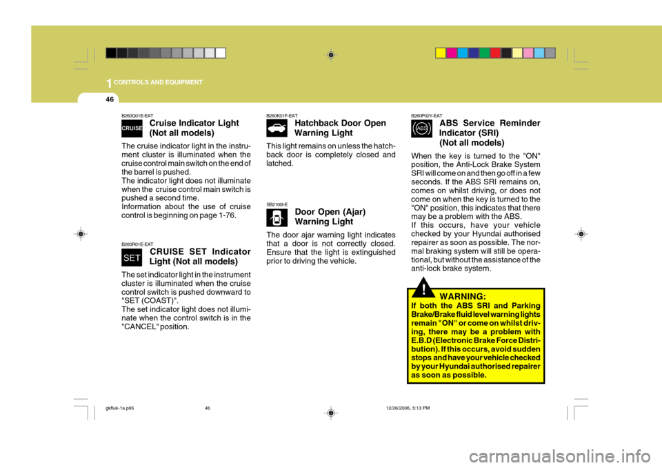
B260Q01E-EAT
Cruise Indicator Light (Not all models)
The cruise indicator light in the instru- ment cluster is illuminated when thecruise control main switch on the end of the barrel is pushed. The indicator light does not illuminatewhen the cruise control main switch is pushed a second time. Information about the use of cruisecontrol is beginning on page 1-76.
B260R01E-EAT CRUISE SET Indicator
Light (Not all models)
The set indicator light in the instrument cluster is illuminated when the cruisecontrol switch is pushed downward to "SET (COAST)". The set indicator light does not illumi-nate when the control switch is in the "CANCEL" position. B260K01F-EAT
Hatchback Door Open
Warning Light
This light remains on unless the hatch- back door is completely closed andlatched.
SB2100I-E Door Open (Ajar) Warning Light
The door ajar warning light indicates that a door is not correctly closed. Ensure that the light is extinguishedprior to driving the vehicle.
B260P02Y-EAT ABS Service Reminder
Indicator (SRI)
(Not all models)
When the key is turned to the "ON" position, the Anti-Lock Brake System SRI will come on and then go off in a fewseconds. If the ABS SRI remains on, comes on whilst driving, or does not come on when the key is turned to the"ON" position, this indicates that there may be a problem with the ABS. If this occurs, have your vehiclechecked by your Hyundai authorised repairer as soon as possible. The nor- mal braking system will still be opera-tional, but without the assistance of the anti-lock brake system.
WARNING:
If both the ABS SRI and Parking Brake/Brake fluid level warning lightsremain "ON" or come on whilst driv- ing, there may be a problem with E.B.D (Electronic Brake Force Distri-bution). If this occurs, avoid sudden stops and have your vehicle checked by your Hyundai authorised repaireras soon as possible.
!
gkfluk-1a.p65 12/26/2006, 5:13 PM
46
Page 314 of 483
1
CONTROLS AND EQUIPMENT
47
!
INSTRUMENT CLUSTER
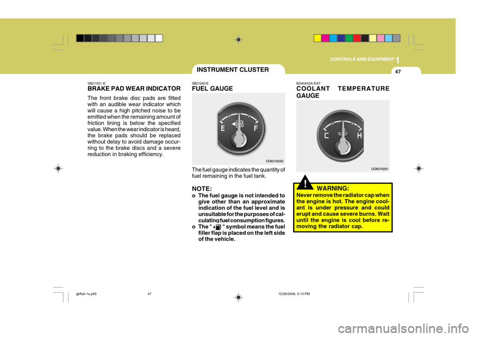
SB210S1-E BRAKE PAD WEAR INDICATOR The front brake disc pads are fitted with an audible wear indicator whichwill cause a high pitched noise to be emitted when the remaining amount of friction lining is below the specifiedvalue. When the wear indicator is heard, the brake pads should be replaced without delay to avoid damage occur-ring to the brake discs and a severe reduction in braking efficiency. SB215A2-E FUEL GAUGE The fuel gauge indicates the quantity of fuel remaining in the fuel tank. NOTE:
o The fuel gauge is not intended to
give other than an approximate indication of the fuel level and isunsuitable for the purposes of cal- culating fuel consumption figures.
o The "
" symbol means the fuel
filler flap is placed on the left side of the vehicle. B290A02A-EAT COOLANT TEMPERATURE GAUGE
WARNING:
Never remove the radiator cap when the engine is hot. The engine cool- ant is under pressure and could erupt and cause severe burns. Waituntil the engine is cool before re- moving the radiator cap.
OGK016259
OGK016261
gkfluk-1a.p65 12/26/2006, 5:13 PM
47
Page 315 of 483
1CONTROLS AND EQUIPMENT
48
!
The needle on the engine coolant tem- perature gauge should stay in the nor-mal range. If it moves across the dial to "H" (HOT), pull over and stop as soon as possible and turn off the engine.Then open the bonnet and check the coolant level and the water pump drive belt. If you suspect cooling systemtrouble, have your cooling system checked by Hyundai authorised repairer as soon as possible.
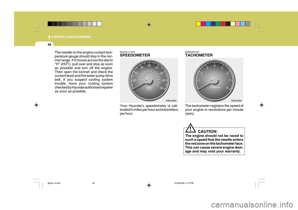
B300A01Y-EAT SPEEDOMETER Your Hyundai's speedometer is cali- brated in miles per hour and kilometers per hour. B330A03A-AAT TACHOMETER The tachometer registers the speed of your engine in revolutions per minute (rpm).
CAUTION:
The engine should not be raced tosuch a speed that the needle entersthe red zone on the tachometer face. This can cause severe engine dam- age and may void your warranty.
OGK016264
OGK016265
gkfluk-1a.p65 12/26/2006, 5:13 PM
48
Page 316 of 483
1
CONTROLS AND EQUIPMENT
49
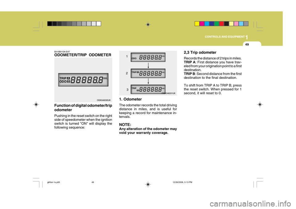
B310B01GK-EAT ODOMETER/TRIP ODOMETER Function of digital odometer/trip odometer Pushing in the reset switch on the right side of speedometer when the ignition switch is turned "ON" will display thefollowing sequence: 1. Odometer The odometer records the total driving distance in miles, and is useful forkeeping a record for maintenance in- tervals. NOTE: Any alteration of the odometer may void your warranty coverage.2,3 Trip odometer Records the distance of 2 trips in miles. TRIP A
: First distance you have trav-
eled from your origination point to a first destination. TRIP B : Second distance from the first
destination to the final destination. To shift from TRIP A to TRIP B, press the reset switch. When pressed for 1 second, it will reset to 0.
OGK046030UK OGK046031UK
1
2 3
gkfluk-1a.p65 12/26/2006, 5:13 PM
49
Page 317 of 483
1CONTROLS AND EQUIPMENT
50TRIP COMPUTER
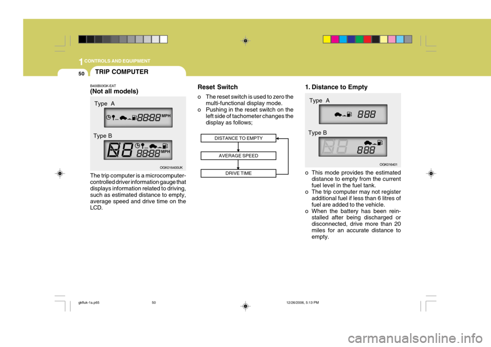
B400B03GK-EAT (Not all models) The trip computer is a microcomputer- controlled driver information gauge that displays information related to driving, such as estimated distance to empty,average speed and drive time on the LCD. Reset Switch
o The reset switch is used to zero the
multi-functional display mode.
o Pushing in the reset switch on the left side of tachometer changes the display as follows; 1. Distance to Empty
o This mode provides the estimated
distance to empty from the current fuel level in the fuel tank.
o The trip computer may not register additional fuel if less than 6 litres offuel are added to the vehicle.
o When the battery has been rein- stalled after being discharged ordisconnected, drive more than 20miles for an accurate distance to empty.
DISTANCE TO EMPTY
AVERAGE SPEED DRIVE TIME
OGK016400UK OGK016401
Type A
Type B Type A
Type B
gkfluk-1a.p65 12/26/2006, 5:13 PM
50
Page 318 of 483
1
CONTROLS AND EQUIPMENT
51
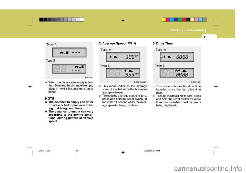
o When the distance to empty is less
than 30 miles, the distance to empty digits (---) will blink until more fuel is added.
NOTE:
o The distance to empty can differ from the actual tripmeter accord- ing to driving conditions.
o The distance to empty can vary according to the driving condi-tions, driving pattern or vehicle speed. 2. Average Speed (MPH)
o This mode indicates the average
speed travelled since the last aver- age speed reset.
o To reset the average speed to zero, press and hold the reset switch formore than 1 second whilst the aver- age speed is being displayed. 3. Drive Time
o This mode indicates the drive time
travelled since the last drive time reset.
o To reset the drive time to zero, press and hold the reset switch for morethan 1 second whilst the drive time isbeing displayed.
OGK016402UKOGK016403
Type A
Type B Type A
Type B
OGK046033
Type A
Type B
gkfluk-1a.p65 12/26/2006, 5:13 PM
51
Page 319 of 483
1CONTROLS AND EQUIPMENT
52MULTI GAUGE
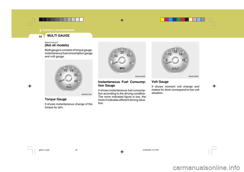
B330C01GK-EAT (Not all models) Multi gauge is consists of torque gauge, instantaneous fuel consumption gaugeand volt gauge.
Instantaneous Fuel Consump- tion Gauge It shows instantaneous fuel consump- tion according to the driving condition. The more indicated figure is low, the more it indicates efficient driving situa-tion.
Torque Gauge It shows instantaneous change of the torque by rpm. Volt Gauge It shows moment volt change and makes for diver correspond to low voltsituation.
B330C01GK B330C04GK
B330C03GK
gkfluk-1a.p65
12/26/2006, 5:13 PM
52
Page 320 of 483
1
CONTROLS AND EQUIPMENT
53MULTI FUNCTION SWITCH
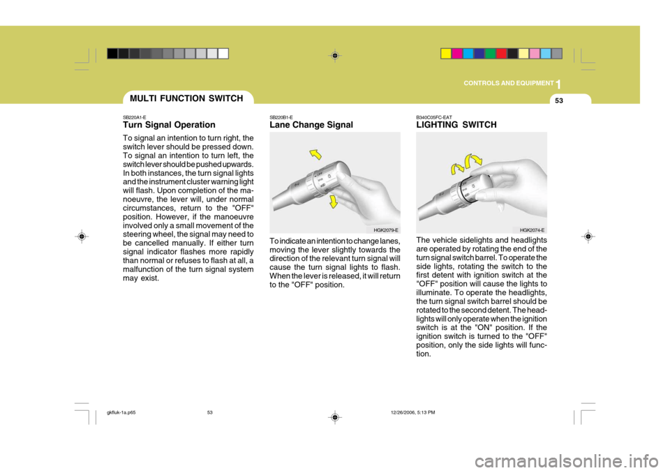
SB220A1-E Turn Signal Operation To signal an intention to turn right, the switch lever should be pressed down. To signal an intention to turn left, the switch lever should be pushed upwards.In both instances, the turn signal lights and the instrument cluster warning light will flash. Upon completion of the ma-noeuvre, the lever will, under normal circumstances, return to the "OFF" position. However, if the manoeuvreinvolved only a small movement of the steering wheel, the signal may need to be cancelled manually. If either turnsignal indicator flashes more rapidly than normal or refuses to flash at all, a malfunction of the turn signal systemmay exist. SB220B1-E Lane Change Signal To indicate an intention to change lanes, moving the lever slightly towards the direction of the relevant turn signal will cause the turn signal lights to flash.When the lever is released, it will return to the "OFF" position.B340C05FC-EAT LIGHTING SWITCH The vehicle sidelights and headlights are operated by rotating the end of the turn signal switch barrel. To operate theside lights, rotating the switch to the first detent with ignition switch at the "OFF" position will cause the lights toilluminate. To operate the headlights, the turn signal switch barrel should be rotated to the second detent. The head-lights will only operate when the ignition switch is at the "ON" position. If the ignition switch is turned to the "OFF"position, only the side lights will func- tion.
HGK2079-EHGK2074-E
gkfluk-1a.p65
12/26/2006, 5:13 PM
53