Hyundai Elantra 2006 Owner's Manual
Manufacturer: HYUNDAI, Model Year: 2006, Model line: Elantra, Model: Hyundai Elantra 2006Pages: 277, PDF Size: 10.18 MB
Page 251 of 277
6 DO-IT-YOURSELF MAINTENANCE
42
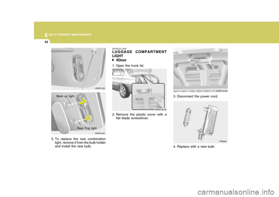
G270C01L-GAT
LUGGAGE COMPARTMENT LIGHT
4Door
1. Open the trunk lid.
2. Remove the plastic cover with a flat blade screwdriver.
3. Disconnect the power cord. HXDFL341B
HTB284
4. Replace with a new bulb.
HXDFL341A
HXDFL333 HXDFL332
Back up light
3. To replace the rear combination light, remove it from the bulb holder and install the new bulb.
Rear Fog light
Page 252 of 277
6
DO-IT-YOURSELF MAINTENANCE
43
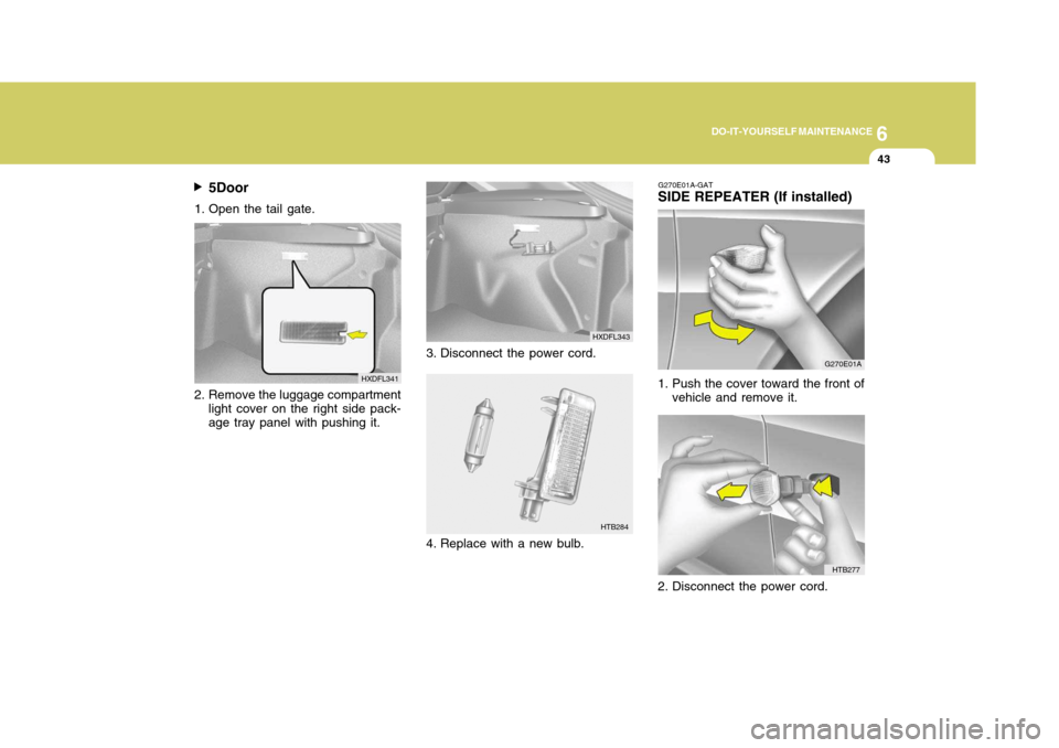
5Door
1. Open the tail gate.
2. Remove the luggage compartment light cover on the right side pack- age tray panel with pushing it. HXDFL341
HTB284
3. Disconnect the power cord.
4. Replace with a new bulb.
HTB277
G270E01A-GAT
SIDE REPEATER (If installed)
G270E01A
1. Push the cover toward the front of vehicle and remove it.
2. Disconnect the power cord.
HXDFL343
Page 253 of 277
6 DO-IT-YOURSELF MAINTENANCE
44
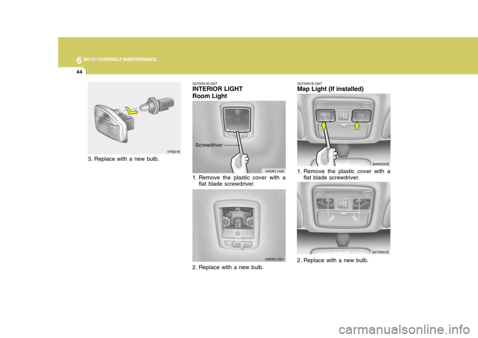
G270G01E-GAT
INTERIOR LIGHT
Room Light
HXDFL1020
1. Remove the plastic cover with a flat blade screwdriver.
2. Replace with a new bulb. HXDFL1021
Screwdriver G270H01E-GAT
Map Light (If installed)
B460D02E
1. Remove the plastic cover with a flat blade screwdriver.
G270H01E
HTB278
3. Replace with a new bulb.
2. Replace with a new bulb.
Page 254 of 277
6
DO-IT-YOURSELF MAINTENANCE
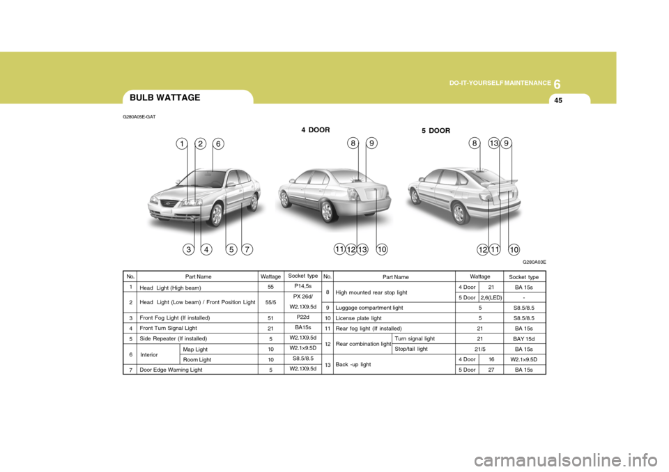
45BULB WATTAGE
1357
4
G280A05E-GAT
G280A03E
16
31110
8
4 DOOR
5 DOOR
111012
8132
12
99
Part Name
High mounted rear stop light Luggage compartment light License plate light Rear fog light (If installed) Back -up light
No.
8 9
10 11 12 13
Wattage
55
55/5
51 215
1010
5 Socket type
BA 15s -
S8.5/8.5 S8.5/8.5 BA 15s
BAY 15d BA 15s
W2.1×9.5D
BA 15s
Part Name
Head Light (High beam) Head Light (Low beam) / Front Position Light Front Fog Light (If installed) Front Turn Signal LightSide Repeater (If installed) Door Edge Warning Light
No
.
1 2 3 45 67
Socket type P14,5s
PX 26d/
W2.1X9.5d P22d
BA15s
W2.1X9.5d W2.1×9.5D
S8.5/8.5
W2.1X9.5dWattage
5 5
2121
21/5
Rear combination light
4 Door5 Door
Map Light Room Light
4 Door 5 Door21
2,6(LED)
Turn signal light Stop/tail light
16 27
Interior
Page 255 of 277
6 DO-IT-YOURSELF MAINTENANCE
46FUSE PANEL DESCRIPTION
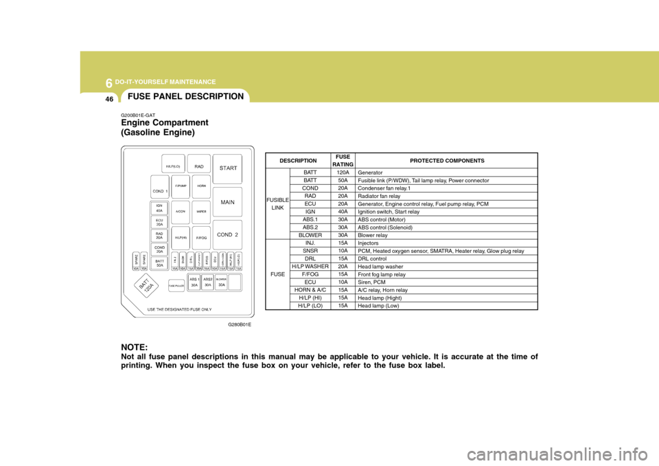
G200B01E-GAT Engine Compartment (Gasoline Engine)
G280B01E
NOTE: Not all fuse panel descriptions in this manual may be applicable to your vehicle. It is accurate at the time of printing. When you inspect the fuse box on your vehicle, refer to the fuse box label.
FUSE
RATING 120A
50A 20A20A 20A 40A30A 30A 30A15A10A 15A 20A15A 10A 15A15A 15A PROTECTED COMPONENTS
Generator
Fusible link (P/WDW), Tail lamp relay, Power connector
Condenser fan relay.1
Radiator fan relay
Generator, Engine control relay, Fuel pump relay, PCM
Ignition switch, Start relay ABS control (Motor) ABS control (Solenoid)
Blower relay Injectors
PCM, Heated oxygen sensor, SMATRA, Heater relay, Glow plug relayDRL control Head lamp washer
Front fog lamp relaySiren, PCM
A/C relay, Horn relay Head lamp (Hight)
Head lamp (Low)
BATT
BATT
COND RADECU
IGN
ABS.1
ABS.2
BLOWER INJ.
SNSR
DRL
H/LP WASHER F/FOG
ECU
HORN & A/C
H/LP (HI)
H/LP (LO)
FUSIBLE
LINK
FUSE
DESCRIPTION
Page 256 of 277

6
DO-IT-YOURSELF MAINTENANCE
47
G280C01E
G200C01E-GAT
(Diesel Engine)
FUSE
RATING 120A50A 30A 30A30A 40A 30A30A 30A 80A60A 30A 30A15A 10A 15A20A 15A 10A15A 15A 15A PROTECTED COMPONENTS
Generator
Fusible link (P/WDW), Tail lamp relay, Power connector
Condenser fan relay.1
Radiator fan relay
Generator, Engine control relay, Fuel pump relay, PCM
Ignition switch, Start relay ABS control (Motor) ABS control (Solenoid)
Blower relay
Grow plug relay
Heater relay #1
Heater relay #2
Fuel filter relay Injectors
PCM, Heated oxygen sensor, SMATRA, Heater relay, Glow plug relay DRL control Head lamp washer
Front fog lamp relay Siren, PCM
A/C relay, Horn relayHead lamp (Hight)
Head lamp (Low)
BATT
BATT
COND RADECU
IGN
ABS.1
ABS.2
BLOWER
GLOW PLUG HEATER #1
HEATER #2
FUEL FILTER
INJ.
SNSR DRL
H/LP WASHER
F/FOGECU
HORN & A/C
H/LP (HI)
H/LP (LO)
FUSIBLE
LINK
FUSE
DESCRIPTION
Page 257 of 277

6 DO-IT-YOURSELF MAINTENANCE
48
G200D01E-GAT Inner Panel
G280D01EFUSE
RATING
10A 10A15A 10A 10A10A10A 10A10A 10A 10A10A 30A 20A15A 15A 10A15A 10A 10A15A 20A 20A10A 15A 30A PROTECTED COMPONENTS
Turn signal lamps, Back-up lamp
Pre-excitation resistor, Instrument cluster (IND)SRS control
Hazard relay, Hazard lamps A/C Control
Shor t connector, Illumination lamps, Tail lamp (RH), Head lamp washer
Tail lamp (LH), Exterior lamps
B/Alarm relay
Digital clock, Power outside mirror & mirror folding, Audio
Cruise control, PCM, Vehicle speed sensor, Ignition coil ABS control
Instrument cluster (Air bag IND)
Defogger relay
Power antenna
Power door lock control, Sunroof
Stop lamps, Power window, Power outside mirror folding
Rear window & outside mirror defogger, A/C control
Cigarette lighter, Power outlet
Rear fog lamps
Head lamp, Head lamp washer, Fuel filter heating Rear wiper & washer
Front wiper & washer
Seat warmer
Blower & A/C control, ETACM, Sunroof controller, Electronic chrome mirror
Door lamps, Instrument cluster, Data link connector, Multipurpose check
connector, Room lamps, ETACM, Audio, Power connector
Power window
T/SIG
CLUSTER
A/BAG
HAZARD A/C SW
TAIL-RH TAIL-LH START
AUDIO
E C UA B S
A/BAG IND RR HTRA M P
S/ROOF
STOP
HTD MIR C/LIGHT
RR FOG I G N
R/WIPER
F/WIPER S/HTR
A/CON
ROOM LP
P/WINDOW
FUSE
FUSIBLE LINK
DESCRIPTION
Page 258 of 277
Emission Control System ............................................ 7-2
Catalytic Converter ...................................................... 7-3
EGR System ................................................................ 7-4
7
EMISSION CONTROL SYSTEM
7
Page 259 of 277
7EMISSION CONTROL SYSTEMS
2EMISSION CONTROL SYSTEMS
H010A01A-GAT
(If installed)
Your Hyundai is equipped with an
emission control system to meet all requirements of the Emission prohibi- tion rules of your province.
There are three emission control sys-
tems which are as follows.
(1) Crankcase emission control sys- tem
(2) Evaporative emission control sys- tem
(3) Exhaust emission control system
In order to assure the proper function
of the emission control systems, it is recommended that you have your carinspected and maintained by an au- thorized Hyundai dealer in accordance with the maintenance schedule in thismanual. H010B01A-AAT
1. Crankcase Emission Control
System
The positive crankcase ventilation
system is employed to prevent airpollution caused by blow-by gasesbeing emitted from the crankcase. This system supplies fresh filtered air to the crankcase through the air in-take hose. Inside the crankcase, the fresh air mixes with blow-by gases, then passes through the PCV valveinto the induction system.
H010C02E-GAT
2. Evaporative Emission
Control System
The Evaporative Emission Control
System is designed to prevent fuel vapors from escaping into the atmo- sphere. Canister
While the engine is inoperative, fuel
vapors generated inside the fuel tank are absorbed and stored in the canis-ter. When the engine is running, the fuel vapors absorbed in the canister are drawn into the induction system through the purge control solenoid valve. Purge Control Solenoid Valve (PCSV)
The purge control solenoid valve is
controlled by the Engine Control Mod- ule (ECM); when the engine coolant temperature is low during idling, thePCSV closes so that evaporated fuel is not taken into the engine. After the engine warms-up during ordinary driv-ing, the PCSV opens so as to intro- duce evaporated fuel to the engine.
H010D01A-AAT
3. Exhaust Emission Control
System
The Exhaust Emission Control Sys-
tem is a highly effective system which controls exhaust emissions while maintaining good vehicle performance.
Page 260 of 277
7
EMISSION CONTROL SYSTEMS
3CATALYTIC CONVERTER
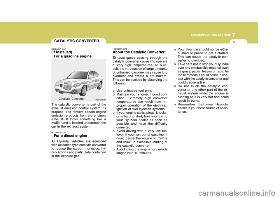
H020A01A-GAT
(If installed) ; For a gasoline engine
HXDFL1032
The catalytic converter is part of the
exhaust emission control system. Its purpose is to remove certain engine emission products from the engine'sexhaust. It looks something like a muffler and is located underneath the car in the exhaust system.
Catalytic Converter H020B01A-GAT
About the Catalytic Converter
Exhaust gases passing through the
catalytic converter cause it to operate at very high temperatures. As a re- sult, the introduction of large amountsof unburned gasoline may cause it to overheat and create a fire hazard. This can be avoided by observing thefollowing:
o Use unleaded fuel only.
o Maintain your engine in good con- dition. Extremely high convertertemperatures can result from im-proper operation of the electrical, ignition or fuel injection systems.
o If your engine stalls, pings, knocks, or is hard to start, take your car toyour Hyundai dealer as soon as possible and have the difficultycorrected.
o Avoid driving with a very low fuel
level. If your run out of gasoline, itcould cause the engine to misfire and result in excessive loading of the catalytic converter.
o Avoid idling the engine for periods longer than 10 minutes. o Your Hyundai should not be either
pushed or pulled to get it started.This can cause the catalytic con- verter to overload.
o Take care not to stop your Hyundai over any combustible material suchas grass, paper, leaves or rags. As these materials could come in con-tact with the catalytic converter and could cause a fire.
o Do not touch the catalytic con- verter or any other part of the ex-haust system while the engine is running as it is very hot and couldresult in burns.
o Remember that your Hyundai
dealer is your best source of assis-tance.
H020D01S-GAT
; For a diesel engine
All Hyundai vehicles are equipped
with oxidation type catalytic converter to reduce the carbon monoxide, hy- drocarbons and particulate containedin the exhaust gas.