ignition INFINITI FX35 2008 Service Manual
[x] Cancel search | Manufacturer: INFINITI, Model Year: 2008, Model line: FX35, Model: INFINITI FX35 2008Pages: 3924, PDF Size: 81.37 MB
Page 500 of 3924

TROUBLE DIAGNOSISATC-95
< SERVICE INFORMATION >
C
DE
F
G H
I
K L
M A
B
AT C
N
O P
3. Check voltage between intake sensor harness connector M254 terminal 2 and ground.
OK or NG
OK >> GO TO 2.
NG >> GO TO 4.
2.CHECK CIRCUIT CONTINUITY BETWEEN INTAKE SENSOR AND UNIFIED METER AND A/C AMP.
1. Turn ignition switch OFF.
2. Disconnect unified meter and A/C amp. connector.
3. Check continuity between intake sensor harness connector M254 terminal 1 and unified meter and A/C amp. harness con-
nector M57 terminal 49.
OK or NG
OK >> GO TO 3.
NG >> Repair harness or connector.
3.CHECK INTAKE SENSOR
Refer to "Intake Sensor".
OK or NG
OK >> 1. Replace unified meter and A/C amp. 2. Go to self-diagnosis ATC-43, "
Self-Diagnosis Function" and perform self-diagnosis STEP-2.
Confirm that code No. 20 is displayed.
NG >> 1. Replace intake sensor. 2. Go to self-diagnosis ATC-43, "
Self-Diagnosis Function" and perform self-diagnosis STEP-2.
Confirm that code No. 20 is displayed.
4.CHECK CIRCUIT CONTINUITY BETWEEN INTAKE SENSOR AND UNIFIED METER AND A/C AMP.
1. Turn ignition switch OFF.
2. Disconnect unified meter and A/C amp. connector.
3. Check continuity between intake sensor harness connector M254 terminal 2 and unified meter and A/C amp. harness con-
nector M57 terminal 41.
4. Check continuity between intake sensor harness connector M254 terminal 2 and ground.
OK or NG
OK >> 1. Replace unified meter and A/C amp. 2. Go to self-diagnosis ATC-43, "
Self-Diagnosis Function" and perform self-diagnosis STEP-2.
Confirm that code No. 20 is displayed.
NG >> Repair harness or connector.
COMPONENT INSPECTION
Intake Sensor
2 – Ground : Approx. 5 V
RJIA2031E
1 – 49 : Continuity should exist.
RJIA2032E
2 – 41 : Continuity should exist.
2 – Ground : Continuity should not exist.
RJIA2033E
3AA93ABC3ACD3AC03ACA3AC03AC63AC53A913A773A893A873A873A8E3A773A983AC73AC93AC03AC3
3A893A873A873A8F3A773A9D3AAF3A8A3A8C3A863A9D3AAF3A8B3A8C
Page 547 of 3924

ATC-142
< SERVICE INFORMATION >
SERVICE DATA AND SPECIFICATIONS (SDS)
SERVICE DATA AND SPECIFICATIONS (SDS)
CompressorINFOID:0000000001328235
LubricantINFOID:0000000001328236
RefrigerantINFOID:0000000001328237
Engine Idling SpeedINFOID:0000000001328238
Refer to EC-593, "Idle Speed and Ignition Timing" (VQ35DE) or EC-1196, "Idle Speed and Ignition Timing"
(VK45DE).
Belt TensionINFOID:0000000001328239
Refer to EM-149, "Standard and Limit" (VQ35DE) or EM-266, "Standard and Limit" (VK45DE).
Model Calsonic Kansei make CWV-618
Ty p e V-6 variable displacement
Displacement
cm
3 (cu in)/rev Max. 184 (11.228)
Min. 14.5 (0.885)
Cylinder bore × stroke
mm (in) 37 (1.46)
× [2.3 - 28.6 (0.091 - 1.126)]
Direction of rotation Clockwise (viewed from drive end)
Drive belt Poly V
ModelCalsonic Kansei make CWV-618
Name Nissan A/C System Oil Type S (DH-PS)
Capacity
m (US fl oz, lmp fl oz) Total in system 180 (6.0, 6.3)
Compressor (Service part) charging
amount
180 (6.0, 6.3)
Ty p e
HFC-134a (R-134a)
Capacity
kg (lb) 0.55 (1.21)
3AA93ABC3ACD3AC03ACA3AC03AC63AC53A913A773A893A873A873A8E3A773A983AC73AC93AC03AC3
3A893A873A873A8F3A773A9D3AAF3A8A3A8C3A863A9D3AAF3A8B3A8C
Page 552 of 3924

AUDIOAV-5
< SERVICE INFORMATION >
C
DE
F
G H
I
J
L
M A
B
AV
N
O P
AUDIO
System DescriptionINFOID:0000000001328672
AUDIO SYSTEM
Refer to Owner's Manual for audio system operating instructions.
Power is supplied at all times
through 15A fuse (No. 32, located in the fuse and fusible link block)
to audio unit terminal 6
to A/C and AV switch terminal 1
to display control unit terminal 1
to woofer terminal 1
to satellite radio tuner terminal 12 (With satellite radio) and
to option connector–2 for satellite radio tuner terminal 12 (Without satellite radio),
through 20A fuse [No.17, located in the fuse block (J/B)]
to BOSE speaker amp. terminal 1.
With the ignition switch in the ACC or ON position, power is supplied
through 10A fuse [No. 6, located in the fuse block (J/B)]
to audio unit terminal 10
to A/C and AV switch terminal 2
to display control unit terminal 10
to satellite radio tuner terminal 16 (With satellite radio) and
to option connector–2 for satellite radio t uner terminal 11 (Without satellite radio).
Ground is supplied through the case of the audio unit.
Ground is also supplied
to BOSE speaker amp. terminal 17
to woofer terminal 2
to satellite radio tuner terminal 15 (With satellite radio) and
to option connector–2 for satellite radio receiver terminal 10 (Without satellite radio)
through body ground B203 and B210,
to A/C and AV switch terminal 5
to display control unit terminals 3,13 and
to display terminal 1
through body ground M35, M45 and M85.
Audio unit, A/C and audio controller are c onnected by FPC (Flexible Print Circuit).
A/C and audio controller integrates A/C switches and audio switches.
When A/C and audio controller is pressed to audio swit ch, it sends audio signal to audio unit. Then audio sig-
nals are supplied
through audio unit terminals 1, 2, 3, 4, 13, 14, 15, and 16
to BOSE speaker amp. terminals 23, 24, 25, 26, 27, 28, 29, and 30.
Audio signals are amplified by the BOSE speaker amp.
The amplified audio signals are supplied
through BOSE speaker amp. terminals 2, 3, 4, 9,10,11,12, 13, 14, 15, 16, 18, 19 and 20
to terminals 1 and 2 of front door speaker LH and RH
to terminals 1 and 2 of rear door speaker LH and RH
to terminals 1 and 2 of tweeter LH and RH
to terminals 1 and 2 of instrument speaker LH, RH, and CENTER, and
to terminals 7 and 8 of woofer.
When one of audio steering wheel switch is press ed to ON (With telephone system), mode ON (Without
telephone system), seek up, or volume up, resistanc e in steering switch circuit changes depending on which
button is pressed.
When one of audio steering wheel switch is pressed to mode ON (With telephone system), power ON (Without
telephone system), seek down, or volume down, resi stance in audio steering wheel switch circuit changes
depending on which button is pressed.
SPEED SENSITIVE VOLUME SYSTEM
Volume level of this system gone up and down automatical ly in proportion to the vehicle speed. And the con-
trol level can be selected by the customer.
3AA93ABC3ACD3AC03ACA3AC03AC63AC53A913A773A893A873A873A8E3A773A983AC73AC93AC03AC3
3A893A873A873A8F3A773A9D3AAF3A8A3A8C3A863A9D3AAF3A8B3A8C
Page 575 of 3924
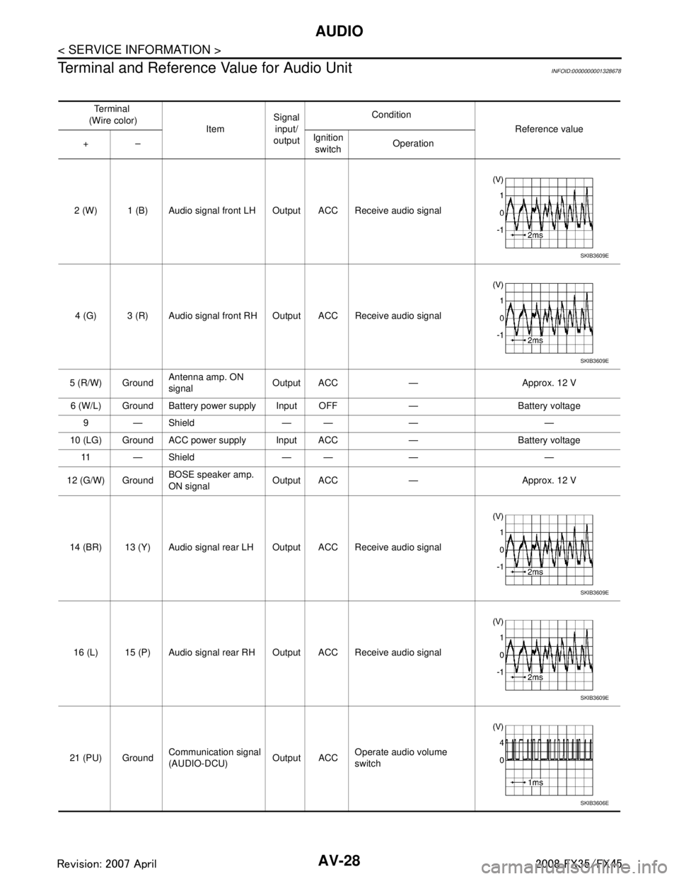
AV-28
< SERVICE INFORMATION >
AUDIO
Terminal and Reference Value for Audio Unit
INFOID:0000000001328678
Te r m i n a l
(Wire color) ItemSignal
input/
output Condition
Reference value
+– Ignition
switch Operation
2 (W) 1 (B) Audio signal front LH Output ACC Receive audio signal
4 (G) 3 (R) Audio signal front RH Output ACC Receive audio signal
5 (R/W) Ground Antenna amp. ON
signal
Output ACC — Approx. 12 V
6 (W/L) Ground Battery power supply Input OFF — Battery voltage 9—Shield —— — —
10 (LG) Ground ACC power supply Input ACC — Battery voltage 11 — S h i e l d — — — —
12 (G/W) Ground BOSE speaker amp.
ON signal Output ACC — Approx. 12 V
14 (BR) 13 (Y) Audio signal rear LH Output ACC Receive audio signal
16 (L) 15 (P) Audio signal rear RH Output ACC Receive audio signal
21 (PU) Ground Communication signal
(AUDIO-DCU) Output ACCOperate audio volume
switch
SKIB3609E
SKIB3609E
SKIB3609E
SKIB3609E
SKIB3606E
3AA93ABC3ACD3AC03ACA3AC03AC63AC53A913A773A893A873A873A8E3A773A983AC73AC93AC03AC3
3A893A873A873A8F3A773A9D3AAF3A8A3A8C3A863A9D3AAF3A8B3A8C
Page 576 of 3924
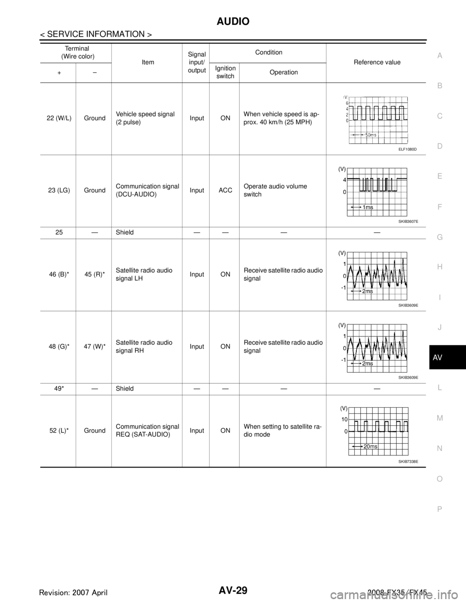
AUDIOAV-29
< SERVICE INFORMATION >
C
DE
F
G H
I
J
L
M A
B
AV
N
O P
22 (W/L) Ground Vehicle speed signal
(2 pulse) Input ONWhen vehicle speed is ap-
prox. 40 km/h (25 MPH)
23 (LG) Ground Communication signal
(DCU-AUDIO)
Input ACCOperate audio volume
switch
25 — Shield — — — —
46 (B)* 45 (R)* Satellite radio audio
signal LH Input ONReceive satellite radio audio
signal
48 (G)* 47 (W)* Satellite radio audio
signal RH Input ON
Receive satellite radio audio
signal
49* — Shield — — — —
52 (L)* Ground Communication signal
REQ (SAT-AUDIO) Input ONWhen setting to satellite ra-
dio mode
Te r m i n a l
(Wire color) ItemSignal
input/
output Condition
Reference value
+– Ignition
switch Operation
ELF1080D
SKIB3607E
SKIB3609E
SKIB3609E
SKIB7338E
3AA93ABC3ACD3AC03ACA3AC03AC63AC53A913A773A893A873A873A8E3A773A983AC73AC93AC03AC3
3A893A873A873A8F3A773A9D3AAF3A8A3A8C3A863A9D3AAF3A8B3A8C
Page 577 of 3924
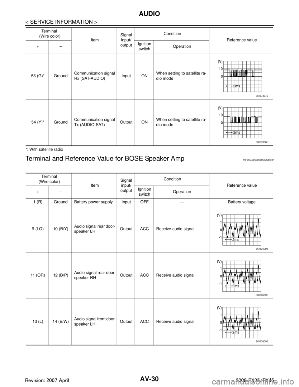
AV-30
< SERVICE INFORMATION >
AUDIO
*: With satellite radio
Terminal and Reference Value for BOSE Speaker AmpINFOID:0000000001328679
53 (G)* GroundCommunication signal
Rx (SAT-AUDIO) Input ONWhen setting to satellite ra-
dio mode
54 (Y)* Ground Communication signal
Tx (AUDIO-SAT)
Output ONWhen setting to satellite ra-
dio mode
Te r m i n a l
(Wire color) ItemSignal
input/
output Condition
Reference value
+– Ignition
switch Operation
SKIB7337E
SKIB7336E
Te r m i n a l
(Wire color) ItemSignal
input/
output Condition
Reference value
+– Ignition
switch Operation
1 (R) Ground Battery power supply Input OFF — Battery voltage
9 (LG) 10 (B/Y) Audio signal rear door-
speaker LH
Output ACC Receive audio signal
11 (OR) 12 (B/P) Audio signal rear door
speaker RH Output ACC Receive audio signal
13 (L) 14 (B/W) Audio signal front door
speaker LH
Output ACC Receive audio signal
SKIB3609E
SKIB3609E
SKIB3609E
3AA93ABC3ACD3AC03ACA3AC03AC63AC53A913A773A893A873A873A8E3A773A983AC73AC93AC03AC3
3A893A873A873A8F3A773A9D3AAF3A8A3A8C3A863A9D3AAF3A8B3A8C
Page 578 of 3924
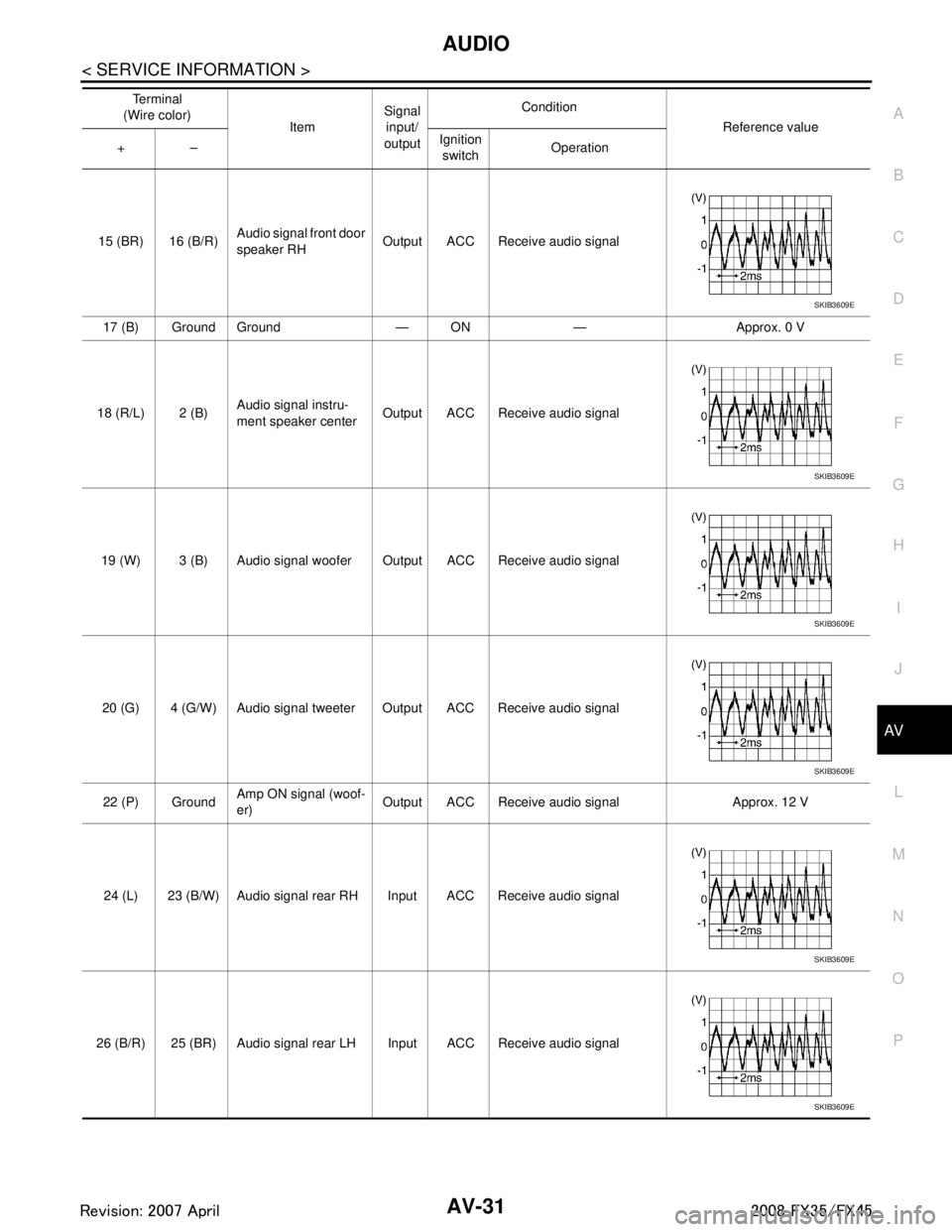
AUDIOAV-31
< SERVICE INFORMATION >
C
DE
F
G H
I
J
L
M A
B
AV
N
O P
15 (BR) 16 (B/R) Audio signal front door
speaker RH Output ACC Receive audio signal
17 (B) Ground Ground — ON — Approx. 0 V
18 (R/L) 2 (B) Audio signal instru-
ment speaker center
Output ACC Receive audio signal
19 (W) 3 (B) Audio signal woofer Output ACC Receive audio signal 20 (G) 4 (G/W) Audio signal tweeter Output ACC Receive audio signal22 (P) Ground Amp ON signal (woof-
er) Output ACC Receive audio signal Approx. 12 V
24 (L) 23 (B/W) Audio signal rear RH Input ACC Receive audio signal
26 (B/R) 25 (BR) Audio signal rear LH Input ACC Receive audio signal Te r m i n a l
(Wire color) ItemSignal
input/
output Condition
Reference value
+– Ignition
switch Operation
SKIB3609E
SKIB3609E
SKIB3609E
SKIB3609E
SKIB3609E
SKIB3609E
3AA93ABC3ACD3AC03ACA3AC03AC63AC53A913A773A893A873A873A8E3A773A983AC73AC93AC03AC3
3A893A873A873A8F3A773A9D3AAF3A8A3A8C3A863A9D3AAF3A8B3A8C
Page 579 of 3924
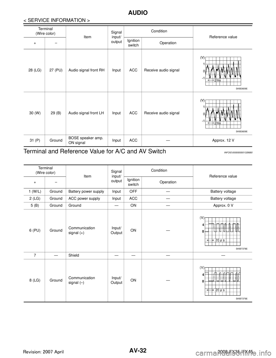
AV-32
< SERVICE INFORMATION >
AUDIO
Terminal and Reference Va lue for A/C and AV Switch
INFOID:0000000001328680
28 (LG) 27 (PU) Audio signal front RH Input ACC Receive audio signal
30 (W) 29 (B) Audio signal front LH Input ACC Receive audio signal31 (P) Ground BOSE speaker amp.
ON signal Input ACC — Approx. 12 V
Te r m i n a l
(Wire color) ItemSignal
input/
output Condition
Reference value
+– Ignition
switch Operation
SKIB3609E
SKIB3609E
Te r m i n a l
(Wire color) ItemSignal
input/
output Condition
Reference value
+– Ignition
switch Operation
1 (W/L) Ground Battery power supply Input OFF — Battery voltage 2 (LG) Ground ACC power supply Input ACC — Battery voltage 5 (B) Ground Ground — ON — Approx. 0 V
6 (PU) Ground Communication
signal (+) Input/
Output ON —
7—Shield —— — —
8 (LG) Ground Communication
signal (–) Input/
Output ON —
SKIB7378E
SKIB7379E
3AA93ABC3ACD3AC03ACA3AC03AC63AC53A913A773A893A873A873A8E3A773A983AC73AC93AC03AC3
3A893A873A873A8F3A773A9D3AAF3A8A3A8C3A863A9D3AAF3A8B3A8C
Page 580 of 3924
AUDIOAV-33
< SERVICE INFORMATION >
C
DE
F
G H
I
J
L
M A
B
AV
N
O P
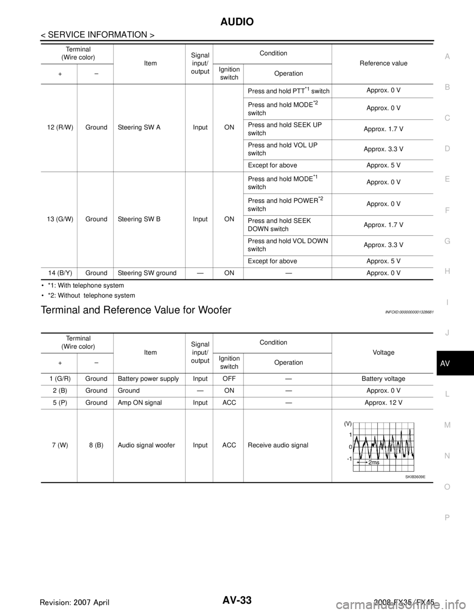
*1: With telephone system
*2: Without telephone system
Terminal and Reference Value for WooferINFOID:0000000001328681
12 (R/W) Ground Steering SW A Input ON Press and hold PTT
*1 switch
Approx. 0 V
Press and hold MODE
*2
switch Approx. 0 V
Press and hold SEEK UP
switch Approx. 1.7 V
Press and hold VOL UP
switch Approx. 3.3 V
Except for above Approx. 5 V
13 (G/W) Ground Steering SW B Input ON Press and hold MODE
*1
switch Approx. 0 V
Press and hold POWER
*2
switch Approx. 0 V
Press and hold SEEK
DOWN switch Approx. 1.7 V
Press and hold VOL DOWN
switch Approx. 3.3 V
Except for above Approx. 5 V
14 (B/Y) Ground Steering SW ground — ON — Approx. 0 V Te r m i n a l
(Wire color) ItemSignal
input/
output Condition
Reference value
+– Ignition
switch Operation
Te r m i n a l
(Wire color) ItemSignal
input/
output Condition
Voltag e
+– Ignition
switch Operation
1 (G/R) Ground Battery power supply Input OFF — Battery voltage 2 (B) Ground Ground — ON — Approx. 0 V
5 (P) Ground Amp ON signal Input ACC — Approx. 12 V
7 (W) 8 (B) Audio signal woofer Input ACC Receive audio signal
SKIB3609E
3AA93ABC3ACD3AC03ACA3AC03AC63AC53A913A773A893A873A873A8E3A773A983AC73AC93AC03AC3
3A893A873A873A8F3A773A9D3AAF3A8A3A8C3A863A9D3AAF3A8B3A8C
Page 581 of 3924

AV-34
< SERVICE INFORMATION >
AUDIO
Terminal and Reference Valu e for Satellite Radio Tuner
INFOID:0000000001328682
A/C and AV Switch Self-Diagnosis FunctionINFOID:0000000001328683
It can check ON/OFF operation of each switch in the A/C and AV sw itch and diagnose the input signals to the
audio steering wheel switch.
Te r m i n a l
(Wire color) ItemSignal
input/
output Condition
Reference value
+– Ignition
switch Operation
2 (B) 1 (R) Satellite radio audio
signal LH
Output ONReceive satellite radio audio
signal
4 (G) 3 (W) Satellite radio audio
signal RH Output ONReceive satellite radio audio
signal
5—Shield —— — —
6—Shield —— — —
8 (L) Ground Communication signal
REQ (SAT-AUDIO)
Output ONWhen setting to satellite ra-
dio mode
9 (L/R) Ground Communication signal
Tx (SAT-AUDIO) Output ONWhen setting to satellite ra-
dio mode
10 (L/W) Ground Communication signal
Rx (AUDIO-SAT) Input ON
When setting to satellite ra-
dio mode
12 (Y) Ground Battery power supply Input OFF — Battery voltage
15 (B) Ground Ground — ON — Approx. 0 V
16 (P) Ground ACC power supply Input ACC — Battery voltage
17 — Satellite radio antenna — — — —
SKIB3609E
SKIB3609E
SKIB7338E
SKIB7337E
SKIB7336E
3AA93ABC3ACD3AC03ACA3AC03AC63AC53A913A773A893A873A873A8E3A773A983AC73AC93AC03AC3
3A893A873A873A8F3A773A9D3AAF3A8A3A8C3A863A9D3AAF3A8B3A8C