check oil INFINITI FX35 2008 Workshop Manual
[x] Cancel search | Manufacturer: INFINITI, Model Year: 2008, Model line: FX35, Model: INFINITI FX35 2008Pages: 3924, PDF Size: 81.37 MB
Page 538 of 3924

REFRIGERANT LINESATC-133
< SERVICE INFORMATION >
C
DE
F
G H
I
K L
M A
B
AT C
N
O P
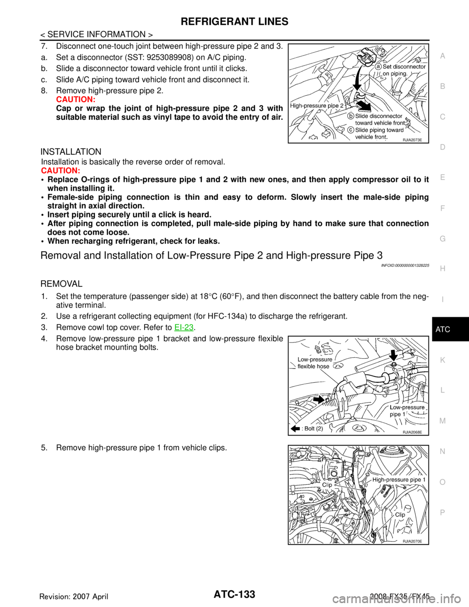
7. Disconnect one-touch joint between high-pressure pipe 2 and 3.
a. Set a disconnector (SST: 9253089908) on A/C piping.
b. Slide a disconnector toward vehicle front until it clicks.
c. Slide A/C piping toward vehicle front and disconnect it.
8. Remove high-pressure pipe 2. CAUTION:
Cap or wrap the joint of hi gh-pressure pipe 2 and 3 with
suitable material such as vinyl tape to avoid the entry of air.
INSTALLATION
Installation is basically the reverse order of removal.
CAUTION:
Replace O-rings of high-pressure pipe 1 and 2 wit h new ones, and then apply compressor oil to it
when installing it.
Female-side piping c onnection is thin and easy to deform. Slowly insert the male-side piping
straight in axial direction.
Insert piping securely until a click is heard.
After piping connection is comple ted, pull male-side piping by hand to make sure that connection
does not come loose.
When recharging refrigerant, check for leaks.
Removal and Installation of Low-Pressu re Pipe 2 and High-pressure Pipe 3
INFOID:0000000001328225
REMOVAL
1. Set the temperature (passenger side) at 18 °C (60 °F), and then disconnect the battery cable from the neg-
ative terminal.
2. Use a refrigerant collecting equipment (f or HFC-134a) to discharge the refrigerant.
3. Remove cowl top cover. Refer to EI-23
.
4. Remove low-pressure pipe 1 bracket and low-pressure flexible hose bracket mounting bolts.
5. Remove high-pressure pipe 1 from vehicle clips.
RJIA2073E
RJIA2068E
RJIA2070E
3AA93ABC3ACD3AC03ACA3AC03AC63AC53A913A773A893A873A873A8E3A773A983AC73AC93AC03AC3
3A893A873A873A8F3A773A9D3AAF3A8A3A8C3A863A9D3AAF3A8B3A8C
Page 539 of 3924
![INFINITI FX35 2008 Workshop Manual
ATC-134
< SERVICE INFORMATION >
REFRIGERANT LINES
6. Disconnect one-touch joints.
a. Set a disconnector [high-pressure side (SST: 9253089908), low-pressure side (SST: 9253089916)] on A/C piping.
b. S INFINITI FX35 2008 Workshop Manual
ATC-134
< SERVICE INFORMATION >
REFRIGERANT LINES
6. Disconnect one-touch joints.
a. Set a disconnector [high-pressure side (SST: 9253089908), low-pressure side (SST: 9253089916)] on A/C piping.
b. S](/img/42/57017/w960_57017-538.png)
ATC-134
< SERVICE INFORMATION >
REFRIGERANT LINES
6. Disconnect one-touch joints.
a. Set a disconnector [high-pressure side (SST: 9253089908), low-pressure side (SST: 9253089916)] on A/C piping.
b. Slide a disconnector toward vehicle front until it clicks.
c. Slide A/C piping toward vehicle front and disconnect it. CAUTION:
Cap or wrap the joint of low-pressure pipe 1 and high-pres-
sure pipe 2 with suitable material such as vinyl tape to
avoid the entry of air.
7. Remove blower unit. Refer to ATC-103
.
8. Remove mounting screws, and then remove air mix door motor (passenger side), mode door motor and evaporator cover.
9. Remove mounting bolt, and then remove low-pressure pipe 2 and high-pressure pipe 3.
CAUTION:
Cap or wrap the joint of expan sion valve with suitable mate-
rial such as vinyl tape to avoid the entry of air.
INSTALLATION
Installation is basically the reverse order of removal.
CAUTION:
Replace O-rings of low-pressure pipe 1, 2 and high-p ressure pipe 2, 3 with new ones, and then apply
compressor oil to it when installing it.
Female-side piping connection is thin and easy to deform. Slowly insert the male-side piping
straight in axial direction.
Insert piping securely until a click is heard.
After piping connection is comp leted, pull male-side piping by hand to make sure that connection
does not come loose.
When recharging refrigerant, check for leaks.
Removal and Installation of Liquid TankINFOID:0000000001328226
REMOVAL
1. Use a refrigerant collecting equipment (for HFC-134a) to discharge the refrigerant.
2. Remove front grille. Refer to EI-22
.
3. Clean liquid tank and its surrounding area, and remove dust and rust from liquid tank. CAUTION:
RJIA2037E
RJIA0940E
RJIA2038E
Low-pressure pipe 1 bracket and low-pressure flexible hose bracket mounting bolts
: 5.5 N·m (0.56 kg-m, 49 in-lb)
3AA93ABC3ACD3AC03ACA3AC03AC63AC53A913A773A893A873A873A8E3A773A983AC73AC93AC03AC3
3A893A873A873A8F3A773A9D3AAF3A8A3A8C3A863A9D3AAF3A8B3A8C
Page 540 of 3924

REFRIGERANT LINESATC-135
< SERVICE INFORMATION >
C
DE
F
G H
I
K L
M A
B
AT C
N
O P
Be sure to clean carefully.
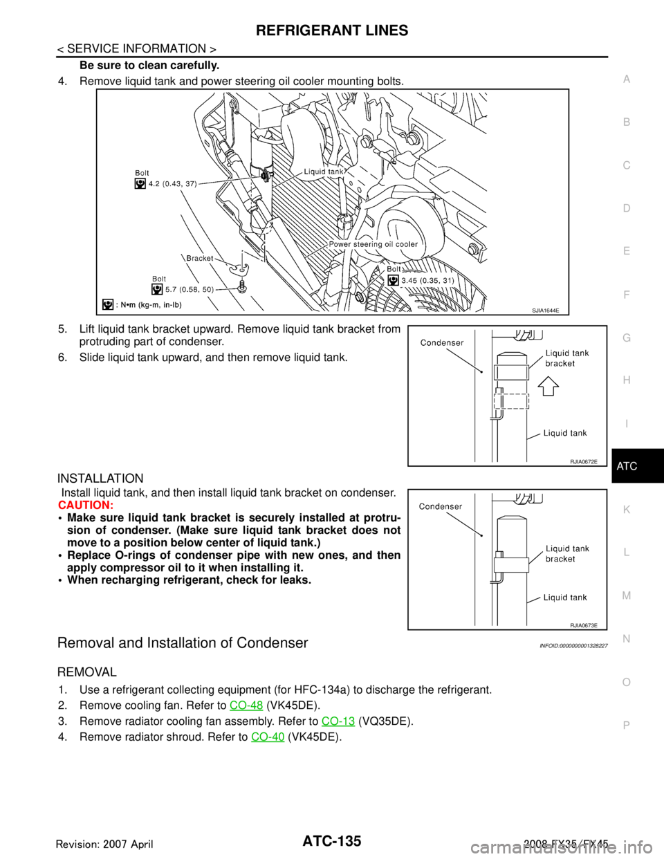
4. Remove liquid tank and power steering oil cooler mounting bolts.
5. Lift liquid tank bracket upward. Remove liquid tank bracket from protruding part of condenser.
6. Slide liquid tank upward, and then remove liquid tank.
INSTALLATION
Install liquid tank, and then install liquid tank bracket on condenser.
CAUTION:
Make sure liquid tank bracket is securely installed at protru- sion of condenser. (Make sure liquid tank bracket does not
move to a position below center of liquid tank.)
Replace O-rings of condenser pipe with new ones, and then
apply compressor oil to it when installing it.
When recharging refrigerant, check for leaks.
Removal and Installation of CondenserINFOID:0000000001328227
REMOVAL
1. Use a refrigerant collecting equipment (f or HFC-134a) to discharge the refrigerant.
2. Remove cooling fan. Refer to CO-48
(VK45DE).
3. Remove radiator cooling fan assembly. Refer to CO-13
(VQ35DE).
4. Remove radiator shroud. Refer to CO-40
(VK45DE).
SJIA1644E
RJIA0672E
RJIA0673E
3AA93ABC3ACD3AC03ACA3AC03AC63AC53A913A773A893A873A873A8E3A773A983AC73AC93AC03AC3
3A893A873A873A8F3A773A9D3AAF3A8A3A8C3A863A9D3AAF3A8B3A8C
Page 542 of 3924

REFRIGERANT LINESATC-137
< SERVICE INFORMATION >
C
DE
F
G H
I
K L
M A
B
AT C
N
O P
After piping connection is comple ted, pull male-side piping by hand to make sure that connection
does not come loose.
When recharging refrigerant, check for leaks.
Removal and Installation of Refrigerant Pressure SensorINFOID:0000000001328228
REMOVAL
1. Remove condenser. Refer to ATC-135, "Removal and Installation of Condenser".
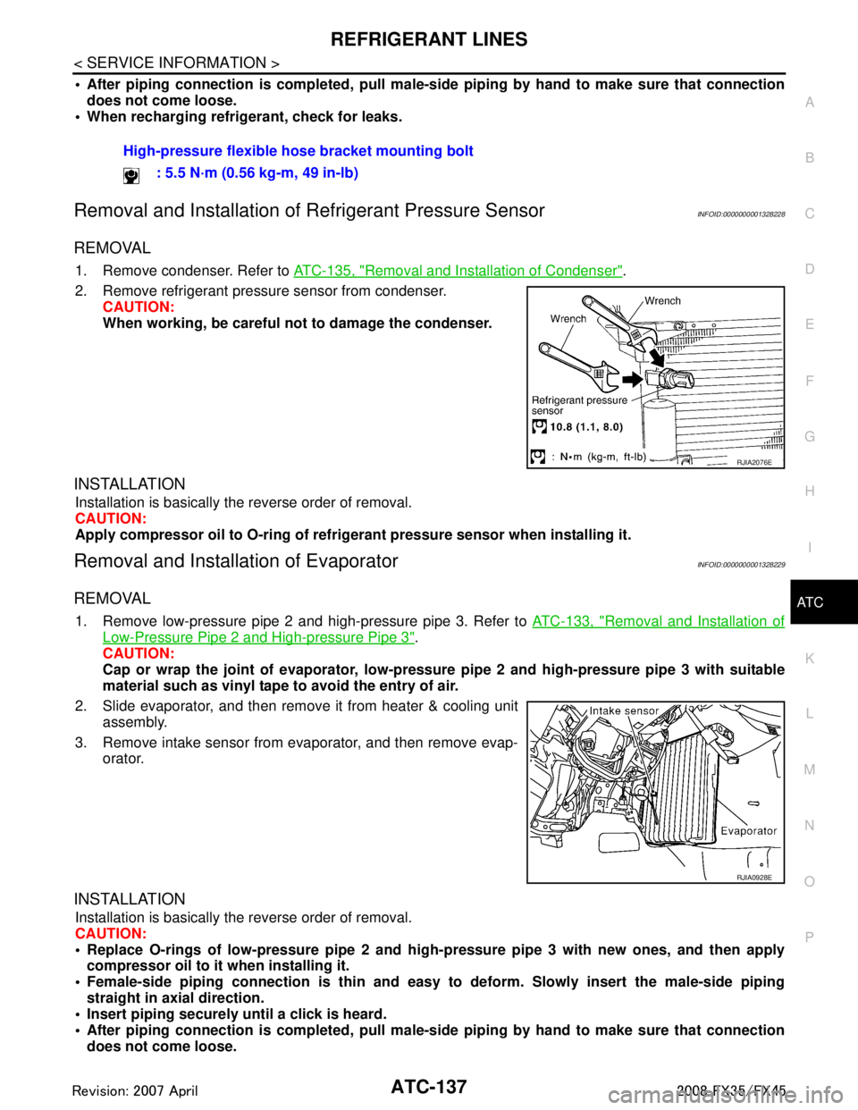
2. Remove refrigerant pressure sensor from condenser. CAUTION:
When working, be careful no t to damage the condenser.
INSTALLATION
Installation is basically the reverse order of removal.
CAUTION:
Apply compressor oil to O-ring of refrig erant pressure sensor when installing it.
Removal and Installation of EvaporatorINFOID:0000000001328229
REMOVAL
1. Remove low-pressure pipe 2 and high-pressure pipe 3. Refer to ATC-133, "Removal and Installation of
Low-Pressure Pipe 2 and High-pressure Pipe 3".
CAUTION:
Cap or wrap the joint of evaporator, low-pressure pipe 2 and high-pressure pipe 3 with suitable
material such as vinyl tape to avoid the entry of air.
2. Slide evaporator, and then remove it from heater & cooling unit assembly.
3. Remove intake sensor from evaporator, and then remove evap- orator.
INSTALLATION
Installation is basically the reverse order of removal.
CAUTION:
Replace O-rings of low-pressure pipe 2 and high- pressure pipe 3 with new ones, and then apply
compressor oil to it when installing it.
Female-side piping c onnection is thin and easy to deform. Slowly insert the male-side piping
straight in axial direction.
Insert piping securely until a click is heard.
After piping connection is comple ted, pull male-side piping by hand to make sure that connection
does not come loose. High-pressure flexible hose bracket mounting bolt
: 5.5 N·m (0.56 kg-m, 49 in-lb)
RJIA2076E
RJIA0928E
3AA93ABC3ACD3AC03ACA3AC03AC63AC53A913A773A893A873A873A8E3A773A983AC73AC93AC03AC3
3A893A873A873A8F3A773A9D3AAF3A8A3A8C3A863A9D3AAF3A8B3A8C
Page 543 of 3924

ATC-138
< SERVICE INFORMATION >
REFRIGERANT LINES
O-rings are different from low-pressure pipe 1 (high-pressure pipe 2) and low-pressure pipe 2 (high-
pressure pipe 3).
Mark the mounting position of intake sensor bracket prior to removal so that the reinstalled sensor
can be located in the same position.
When recharging refrigerant, check for leaks.
Removal and Installation of Expansion ValveINFOID:0000000001328230
REMOVAL
1. Remove evaporator. Refer to ATC-137, "Removal and Installation of Evaporator".
2. Remove mounting bolts, and then remove expansion valve. CAUTION:
Cap or wrap the joint of evaporator with suitable material
such as vinyl tape to avoid the entry of air.
INSTALLATION
Installation is basically the reverse order of removal.
CAUTION:
Replace O-rings of evaporator with new ones, and then apply compressor oil to it when installing it.
O-rings are different from low-pressure pipe 1 (h igh-pressure pipe 2) and low-pressure pipe 2 (high-
pressure pipe 3).
When recharging refrigerant, check for leaks.
Checking of Refrigerant LeaksINFOID:0000000001328231
Perform a visual inspection of all refrigeration parts, fittings, hoses and components for signs of A/C lubricant
leakage, damage and corrosion. A/C lubricant leakage ma y indicate an area of refrigerant leakage. Allow
extra inspection time in these areas when using either an electrical leak detector or fluorescent dye leak
detector (SST: J-42220).
If dye is observed, c onfirm the leak with an electrical leak detector. It is possible a prior leak was repaired and
not properly cleaned.
When searching for leaks, do not stop when one leak is found but continue to check for additional leaks at all
system components and connections.
When searching for refrigerant leaks using an electric al leak detector, move the probe along the suspected
leak area at 1 to 2 inches per second and no further than 1/4 inch from the component.
CAUTION:
Moving the electrical leak detector probe slower and closer to the suspected leak area will improve the
chances of finding a leak.
Checking System for Leaks Using the Fluore scent Leak DetectorINFOID:0000000001328232
1. Check A/C system for leaks using the UV lamp and safety goggles (SST: J-42220) in a low sunlight area
(area without windows preferable). Illuminate all co mponents, fittings and lines. The dye will appear as a
bright green/yellow area at the point of leakage. Fluorescent dye observed at the evaporator drain open-
ing indicates an evaporator core assembly (tubes, core or expansion valve) leak.
2. If the suspected area is difficult to see, use an adjustable mirror or wipe the area with a clean shop rag or
cloth, with the UV lamp for dye residue.
3. After the leak is repaired, remove any residual dye using dye cleaner (SST: J-43872) to prevent future
misdiagnosis. Low-pressure pipe 1 bracket mounting bolt
: 5.5 N·m (0.56 kg-m, 49 in-lb)
RJIA1864E
3AA93ABC3ACD3AC03ACA3AC03AC63AC53A913A773A893A873A873A8E3A773A983AC73AC93AC03AC3
3A893A873A873A8F3A773A9D3AAF3A8A3A8C3A863A9D3AAF3A8B3A8C
Page 544 of 3924

REFRIGERANT LINESATC-139
< SERVICE INFORMATION >
C
DE
F
G H
I
K L
M A
B
AT C
N
O P
4. Perform a system performance check and verify the l eak repair with an approved electrical leak detector.
NOTE:
Other gases in the work area or substances on the A/C components, for example, anti-freeze, windshield
washer fluid, solvents and lubricants, may falsely trigger the leak detector. Make sure the surfaces to be
checked are clean.
Clean with a dry cloth or blow off with shop air.
Do not allow the sensor tip of the detector to contact with any substance. This can also cause false readings
and may damage the detector.
Dye InjectionINFOID:0000000001328233
(This procedure is only necessary when recharging t he system or when the compressor has seized and was
replaced.)
1. Check A/C system static (at rest) pressure. Pressure must be at least 345 kPa (3.52 kg/cm
2, 50 psi).
2. Pour one bottle (1/4 ounce / 7.4 cc) of the A/C refr igerant dye into the injector tool (SST: J-41459).
3. Connect the injector tool to the A/C low-pressure side service valve.
4. Start the engine and switch A/C ON.
5. When the A/C operating (compressor running), inject one bottle (1/4 ounce / 7.4 cc) of fluorescent dye
through the low-pressure service valve using dye inje ctor tool (SST: J-41459) (refer to the manufacture’s
operating instructions).
6. With the engine still running, disconnect the injector tool from the service valve. CAUTION:
Be careful the A/C system or replacing a componen t, pour the dye directly into the open system
connection and proceed wi th the service procedures.
7. Operate the A/C system for a minimum of 20 minutes to mix the dye with the system oil. Depending on the
leak size, operating conditions and location of the leak , it may take from minutes to days for the dye to
penetrate a leak and become visible.
8. Attach a blue label as necessary.
Electrical Leak DetectorINFOID:0000000001328234
PRECAUTIONS FOR HANDLING LEAK DETECTOR
When performing a refrigerant leak check, use an A/C electrical leak
detector (SST) or equivalent. Ensure that the instrument is calibrated
and set properly per the operating instructions.
The leak detector is a delicate device. In order to use the leak detec-
tor properly, read the operating instructions and perform any speci-
fied maintenance.
1. Position probe approximately 5 mm (3/16 in) away from point to
be checked.
SHA196FA
SHA707EA
3AA93ABC3ACD3AC03ACA3AC03AC63AC53A913A773A893A873A873A8E3A773A983AC73AC93AC03AC3
3A893A873A873A8F3A773A9D3AAF3A8A3A8C3A863A9D3AAF3A8B3A8C
Page 732 of 3924

BCS-12
< SERVICE INFORMATION >
BCM (BODY CONTROL MODULE)
ITEMS OF EACH PART
BCM can perform the following functions for each system.
NOTE:
CONSULT-III displays systems equipped in the vehicle.
×:Applicable
NOTE:
*1: Vehicle with remote keyless entry system display this item.
*2: Vehicle with Intelligent Key system display this item.
*3: This item is displayed, but does not function.
WORK SUPPORT
Display Item List
BCM Diagnostic test item Check item, diagnostic test mode Content
Inspection by part WORK SUPPORT Changes setting of each function.
SELF-DIAG RESULTS BCM performs self-diagnosis of CAN communication.
DATA MONITOR Displays the input data of BCM in real time.
CAN DIAG SUPPORT MNTR
The transmit/receive diagnosis result of CAN communication can be
read.
ACTIVE TEST Gives a drive signal to a load to check the operation.
ECU PART NUMBER ECM part number can be read.
CONFIGURATION (Not be used)
System and item CONSULT-III display Diagnostic test mode (Inspection by part)
WORK SUPPORT DATA MONITOR ACTIVE TEST
BCM BCM ×
Power door lock system DOOR LOCK ×××
Rear window defogger REAR DEFOGGER ××
Warning chime BUZZER ××
Room lamp timer INT LAMP ×××
Remote keyless entry system*
1MULTI REMOTE ENT ×××
Headlamp HEAD LAMP ×××
Wiper WIPER ×××
Turn signal lamp
Hazard lamp FLASHER
××
Blower fan switch signal
A/C switch signal AIR CONDITONER
×
Intelligent Key system*
2INTELLIGENT KEY ×
Combination switch COMB SW ×
NVIS IMMU ××
Room lamp battery saver BATTERY SAVER ×× ×
Trunk lid TRUNK*
3××
Vehicle security system THEFT ALM ×××
Retained power control RETAINED PWR ×××
Oil pressure swit ch SIGNAL BUFFER ××
Low tire pressure warning system AIR PRESSURE MONITOR ×××
Panic system PANIC ALARM ×
3AA93ABC3ACD3AC03ACA3AC03AC63AC53A913A773A893A873A873A8E3A773A983AC73AC93AC03AC3
3A893A873A873A8F3A773A9D3AAF3A8A3A8C3A863A9D3AAF3A8B3A8C
Page 986 of 3924

BR-2
< SERVICE INFORMATION >
PRECAUTIONS
SERVICE INFORMATION
PRECAUTIONS
Precaution for Supplemental Restraint System (SRS) "AIR BAG" and "SEAT BELT
PRE-TENSIONER"
INFOID:0000000001612918
The Supplemental Restraint System such as “A IR BAG” and “SEAT BELT PRE-TENSIONER”, used along
with a front seat belt, helps to reduce the risk or severi ty of injury to the driver and front passenger for certain
types of collision. This system includes seat belt switch inputs and dual stage front air bag modules. The SRS
system uses the seat belt switches to determine the front air bag deployment, and may only deploy one front
air bag, depending on the severity of a collision and w hether the front occupants are belted or unbelted.
Information necessary to service the system safely is included in the “SUPPLEMENTAL RESTRAINT SYS-
TEM” and “SEAT BELTS” of this Service Manual.
WARNING:
• To avoid rendering the SRS inopera tive, which could increase the risk of personal injury or death in
the event of a collision which would result in air bag inflation, all maintenance must be performed by
an authorized NISS AN/INFINITI dealer.
Improper maintenance, including in correct removal and installation of the SRS, can lead to personal
injury caused by unintent ional activation of the system. For re moval of Spiral Cable and Air Bag
Module, see the “SUPPLEMEN TAL RESTRAINT SYSTEM”.
Do not use electrical test equipmen t on any circuit related to the SRS unless instructed to in this
Service Manual. SRS wiring harnesses can be identi fied by yellow and/or orange harnesses or har-
ness connectors.
Precaution for Procedure without Cowl Top CoverINFOID:0000000001612920
When performing the procedure after removing cowl top cover, cover
the lower end of windshield with urethane, etc.
Precaution for Brake SystemINFOID:0000000001327604
Clean dust on front brake and rear brake with a vacuum dust collector. Do not blow with compressed air.
Recommended fluid is brake fluid “DOT 3”. MA-9, "
Fluids and Lubricants".
Do not reuse drained brake fluid.
Be careful not to splash brake fluid on painted areas.
To clean or wash all parts of master cylinder, disc brake caliper and wheel cylinder, use new brake fluid.
Do not use mineral oils such as gasoline or kerosene. They will ruin rubber parts of the hydraulic system.
Use a flare nut crowfoot and torque wrench when installing brake
tube.
When installing brake piping, be sure to check torque.
Before working, turn ignition switch OFF and disconnect connec- tors for ABS actuator and electric unit (control unit) or battery neg-
ative terminal.
Burnish the brake contact surfaces after refinishing or replacing drums or rotors, after replacing pads or linings, or if a soft pedal
occurs at very low mileage.
Refer to BR-23, "
Brake Burnishing Procedure" (Front disc brake),
BR-29, "
Brake Burnishing Procedure" (Rear disc brake).
WARNING:
Clean brake pads and shoes with a waste cl oth, then clean with a dust collector.
PIIB3706J
SBR686C
3AA93ABC3ACD3AC03ACA3AC03AC63AC53A913A773A893A873A873A8E3A773A983AC73AC93AC03AC3
3A893A873A873A8F3A773A9D3AAF3A8A3A8C3A863A9D3AAF3A8B3A8C
Page 1000 of 3924

BR-16
< SERVICE INFORMATION >
VACUUM LINES
VACUUM LINES
ComponentINFOID:0000000001327624
Removal and InstallationINFOID:0000000001327625
CAUTION:
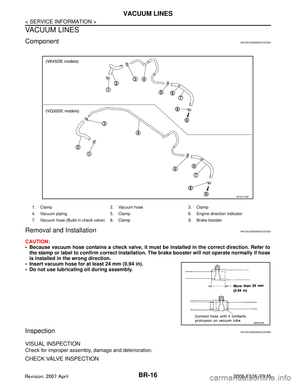
Because vacuum hose contains a check valve, it must be installed in the correct direction. Refer to
the stamp or label to confirm co rrect installation. The brake booster will not ope rate normally if hose
is installed in the wrong direction.
Insert vacuum hose for at least 24 mm (0.94 in).
Do not use lubricating oil during assembly.
InspectionINFOID:0000000001327626
VISUAL INSPECTION
Check for improper assembly, damage and deterioration.
CHECK VALVE INSPECTION
1. Clamp 2. Vacuum hose 3. Clamp
4. Vacuum piping 5. Clamp 6. Engine direction indicator
7. Vacuum hose (Build in check valve) 8. Clamp 9. Brake booster
SFIA1134E
SBR225B
3AA93ABC3ACD3AC03ACA3AC03AC63AC53A913A773A893A873A873A8E3A773A983AC73AC93AC03AC3
3A893A873A873A8F3A773A9D3AAF3A8A3A8C3A863A9D3AAF3A8B3A8C
Page 1005 of 3924

FRONT DISC BRAKEBR-21
< SERVICE INFORMATION >
C
DE
G H
I
J
K L
M A
B
BR
N
O P
3. Remove sliding pins and sliding pin boots from torque member.
4. Place a wooden block as shown in the figure, and blow air from union bolt mounting hole to remove pistons and piston boots.
CAUTION:
Do not get your fingers caught in piston.
5. Using a flat-bladed screwdriver, remove piston seal from cylin- der body.
CAUTION:
Be careful not to damage cylinder inner wall.
INSPECTION AFTER DISASSEMBLY
Cylinder Body
CAUTION:
Use new brake fluid to clean. Do not use mi neral oils such as gasoline or kerosene.
Check the inner wall of cylinder for corrosion, wear, and damage. If a malfunction is detected, replace cylin-
der body.
Minor flaws caused by corrosion or a foreign material can be removed by polishing a surface of the inner wall with a fine sandpaper. Replace cylinder body, if necessary.
Torque Member
Check for wear, cracks, and damage. If a malfunc tion is detected, replace the torque member.
Piston
CAUTION:
The piston sliding surface is plated. Do not polish with sandpaper.
Check piston surface for corrosion, wear, and damage. If a malfunction is detected, replace applicable part.
Sliding Pin, Sliding Pin Bolt, and Sliding Pin Boot
Check sliding pins, sliding pin bolts and sliding pin boots for wear, damage, and cracks. If a malfunction is
detected, replace applicable part.
ASSEMBLY
1. Apply polyglycol ether based lubricant to the piston seal, and
install them to the cylinder body.
CAUTION:
Do not reuse piston seal.
BRB0032D
SFIA0141E
SFIA2920E
3AA93ABC3ACD3AC03ACA3AC03AC63AC53A913A773A893A873A873A8E3A773A983AC73AC93AC03AC3
3A893A873A873A8F3A773A9D3AAF3A8A3A8C3A863A9D3AAF3A8B3A8C