seal INFINITI FX35 2008 Repair Manual
[x] Cancel search | Manufacturer: INFINITI, Model Year: 2008, Model line: FX35, Model: INFINITI FX35 2008Pages: 3924, PDF Size: 81.37 MB
Page 750 of 3924
BL-16
< SERVICE INFORMATION >
HOOD
6. Remove the grommet on the dashboard, and pull the hood lock cable toward the passenger room.CAUTION:
While pulling, be careful not to damage (p eeling) the outside of the hood lock cable.
INSTALLATION
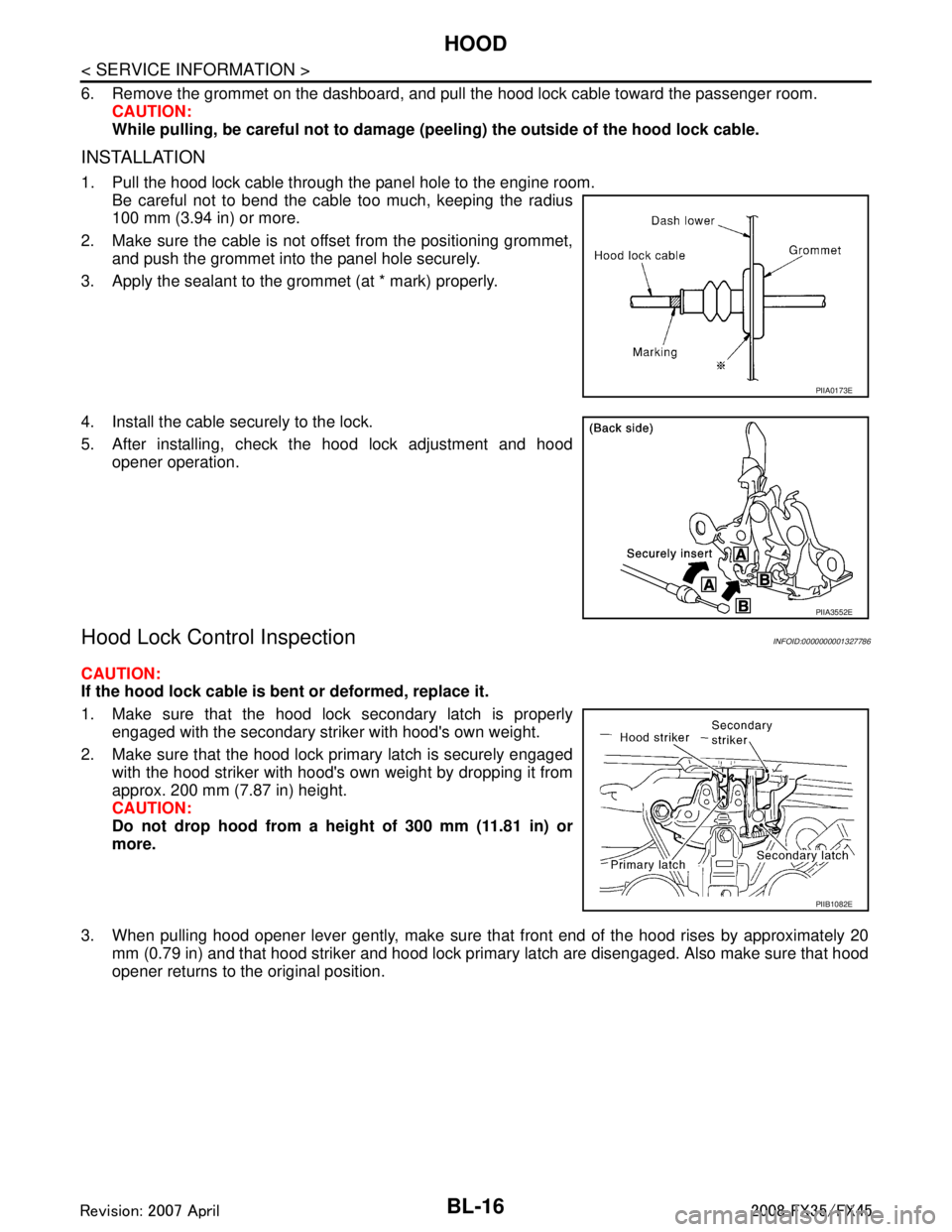
1. Pull the hood lock cable through the panel hole to the engine room.
Be careful not to bend the cable too much, keeping the radius
100 mm (3.94 in) or more.
2. Make sure the cable is not offset from the positioning grommet, and push the grommet into the panel hole securely.
3. Apply the sealant to the grommet (at * mark) properly.
4. Install the cable securely to the lock.
5. After installing, check the hood lock adjustment and hood opener operation.
Hood Lock Control InspectionINFOID:0000000001327786
CAUTION:
If the hood lock cable is bent or deformed, replace it.
1. Make sure that the hood lock secondary latch is properlyengaged with the secondary striker with hood's own weight.
2. Make sure that the hood lock primary latch is securely engaged with the hood striker with hood's own weight by dropping it from
approx. 200 mm (7.87 in) height.
CAUTION:
Do not drop hood from a he ight of 300 mm (11.81 in) or
more.
3. When pulling hood opener lever gently, make sure that front end of the hood rises by approximately 20 mm (0.79 in) and that hood striker and hood lock primary latch are disengaged. Also make sure that hood
opener returns to the original position.
PIIA0173E
PIIA3552E
PIIB1082E
3AA93ABC3ACD3AC03ACA3AC03AC63AC53A913A773A893A873A873A8E3A773A983AC73AC93AC03AC3
3A893A873A873A8F3A773A9D3AAF3A8A3A8C3A863A9D3AAF3A8B3A8C
Page 872 of 3924
BL-138
< SERVICE INFORMATION >
REAR DOOR LOCK
REAR DOOR LOCK
Removal and InstallationINFOID:0000000001327878
REMOVAL
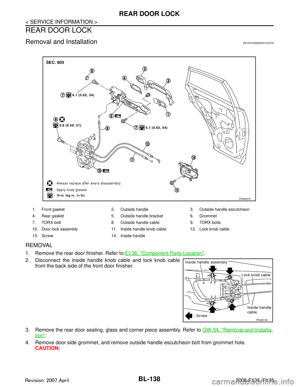
1. Remove the rear door finisher. Refer to EI-36, "Component Parts Location".
2. Disconnect the inside handle knob cable and lock knob cable from the back side of the front door finisher.
3. Remove the rear door sealing, glass and corner piece assembly. Refer to GW-54, "
Removal and Installa-
tion".
4. Remove door side grommet, and remove outside handle escutcheon bolt from grommet hole. CAUTION:
1. Front gasket 2. Outside handle 3. Outside handle escutcheon
4. Rear gasket 5. Outside handle bracket 6. Grommet
7. TORX bolt 8. Outside handle cable 9. TORX bolts
10. Door lock assembly 11. Inside handle knob cable 12. Lock knob cable
13. Screw 14. Inside handle
PIIA6027E
PIIA4014E
3AA93ABC3ACD3AC03ACA3AC03AC63AC53A913A773A893A873A873A8E3A773A983AC73AC93AC03AC3
3A893A873A873A8F3A773A9D3AAF3A8A3A8C3A863A9D3AAF3A8B3A8C
Page 944 of 3924
BL-210
< SERVICE INFORMATION >
BODY REPAIR
2. Do not undercoat the exhaust pipe or other parts which become hot.
3. Do not undercoat rotating parts.
4. Apply bitumen wax after applying undercoating.
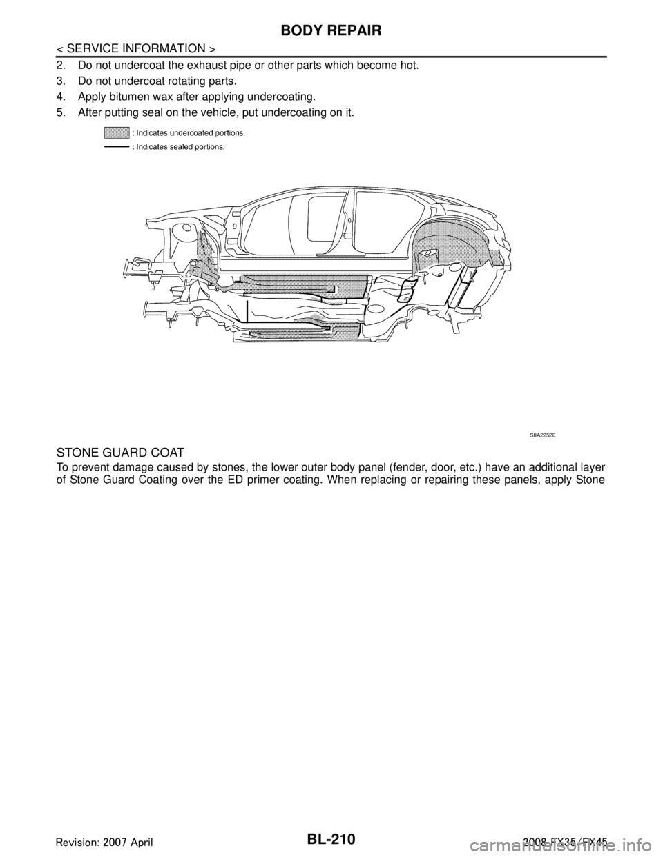
5. After putting seal on the vehicle, put undercoating on it.
STONE GUARD COAT
To prevent damage caused by stones, the lower outer body panel (fender, door, etc.) have an additional layer
of Stone Guard Coating over the ED primer coating. When replacing or repairing these panels, apply Stone
SIIA2252E
3AA93ABC3ACD3AC03ACA3AC03AC63AC53A913A773A893A873A873A8E3A773A983AC73AC93AC03AC3
3A893A873A873A8F3A773A9D3AAF3A8A3A8C3A863A9D3AAF3A8B3A8C
Page 945 of 3924
BODY REPAIRBL-211
< SERVICE INFORMATION >
C
DE
F
G H
J
K L
M A
B
BL
N
O P
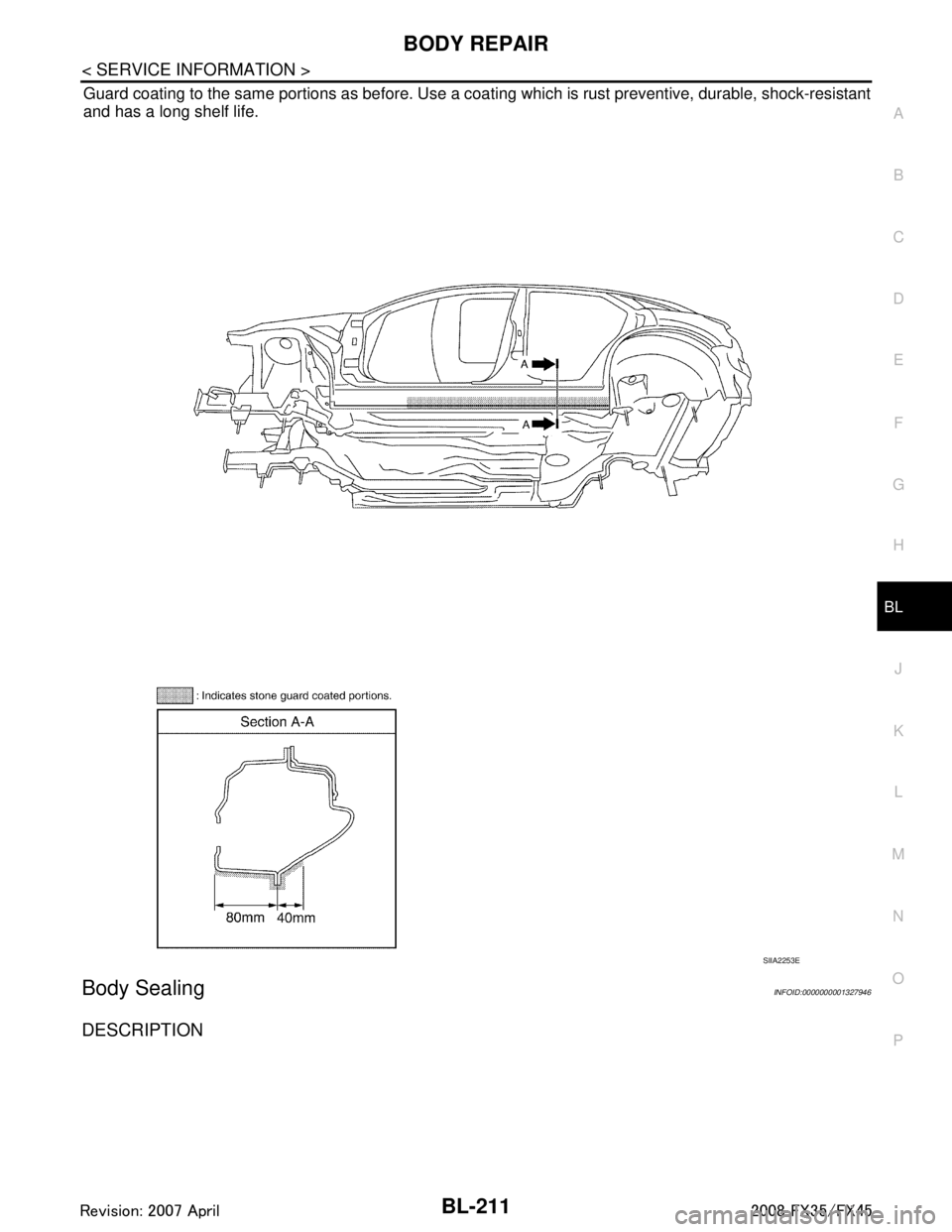
Guard coating to the same portions as before. Use a c oating which is rust preventive, durable, shock-resistant
and has a long shelf life.
Body SealingINFOID:0000000001327946
DESCRIPTION
SIIA2253E
3AA93ABC3ACD3AC03ACA3AC03AC63AC53A913A773A893A873A873A8E3A773A983AC73AC93AC03AC3
3A893A873A873A8F3A773A9D3AAF3A8A3A8C3A863A9D3AAF3A8B3A8C
Page 946 of 3924
BL-212
< SERVICE INFORMATION >
BODY REPAIR
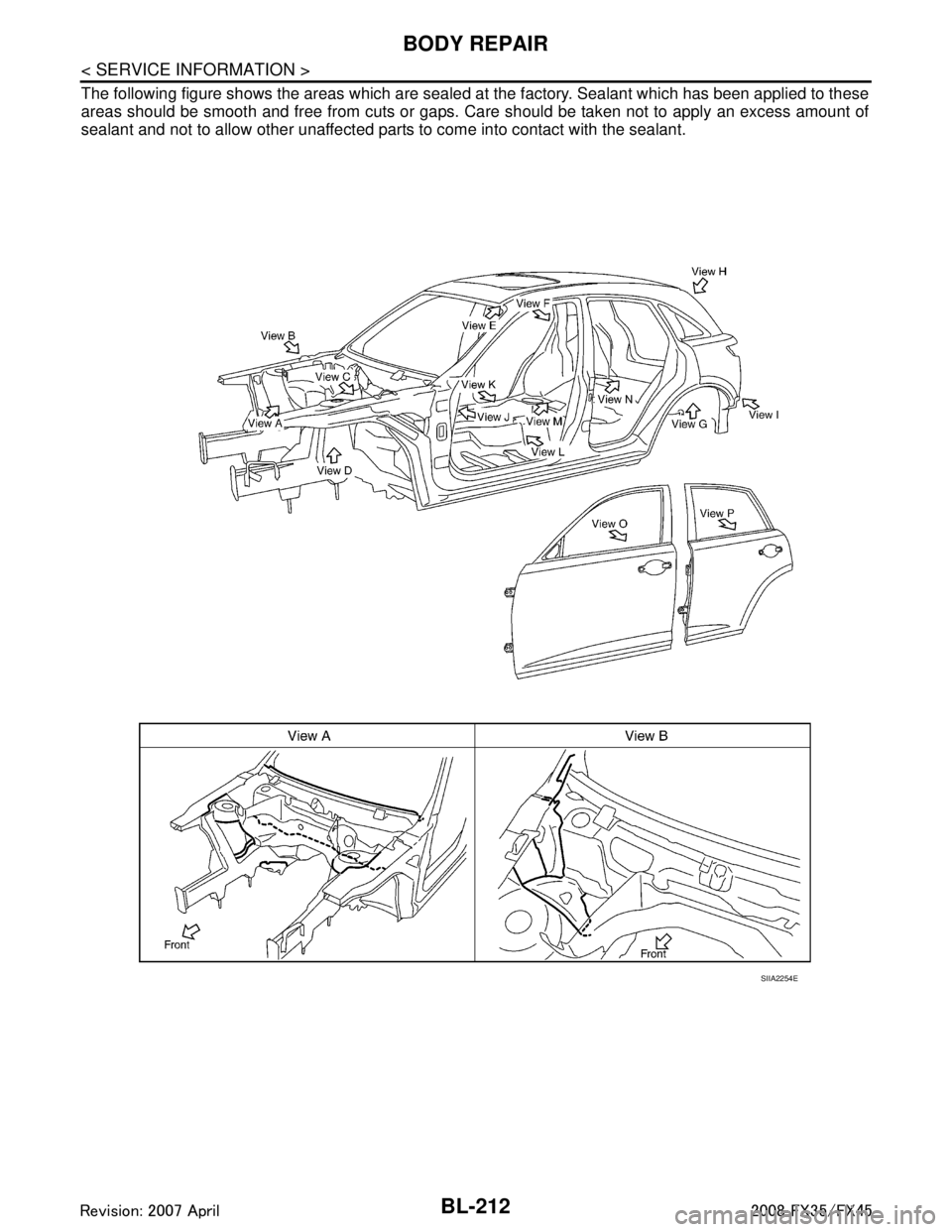
The following figure shows the areas which are sealed at the factory. Sealant which has been applied to these
areas should be smooth and free from cuts or gaps. Care should be taken not to apply an excess amount of
sealant and not to allow other unaffected parts to come into contact with the sealant.
SIIA2254E
3AA93ABC3ACD3AC03ACA3AC03AC63AC53A913A773A893A873A873A8E3A773A983AC73AC93AC03AC3
3A893A873A873A8F3A773A9D3AAF3A8A3A8C3A863A9D3AAF3A8B3A8C
Page 1002 of 3924

BR-18
< SERVICE INFORMATION >
FRONT DISC BRAKE
FRONT DISC BRAKE
On-Vehicle InspectionINFOID:0000000001327627
PAD WEAR INSPECTION
Check the thickness from check hole on cylinder body. Use a scalefor inspection if necessary.
ComponentINFOID:0000000001327628
WARNING:
Clean dust on caliper and brake pad with a vacuum dust collector to minimize the hazard of airborne
particles or other materials.
CAUTION: Standard thickness : 11.0 mm (0.433 in)
Repair limit thickness : 2.0 mm (0.079 in)
MAA0439D
1. Brake hose 2. Union bolt 3. Copper washer
4. Cap 5. Bleed valve 6. Sliding pin bolt
7. Cylinder body 8. Piston seal 9. Piston
10. Piston boot 11. Torque member mounting bolt 12. Sliding pin
13. Sliding pin boot 14. Bushing 15. Torque member
16. Inner shim cover 17. Inner shim 18. Inner pad
19. Pad wear sensor 20. Pad retainer 21. Outer pad
22. Outer shim 23. Outer shim cover
Refer to
GI-8, "
Component" and the followings for the symbols in the figure.
1: Apply rubber grease.
2: Apply PBC (Poly Butyl Cuprysil) grease or silicone-based grease.
3: Apply polyglycol ether based lubricant.
: Apply brake fluid.
PFIA0809E
3AA93ABC3ACD3AC03ACA3AC03AC63AC53A913A773A893A873A873A8E3A773A983AC73AC93AC03AC3
3A893A873A873A8F3A773A9D3AAF3A8A3A8C3A863A9D3AAF3A8B3A8C
Page 1005 of 3924

FRONT DISC BRAKEBR-21
< SERVICE INFORMATION >
C
DE
G H
I
J
K L
M A
B
BR
N
O P
3. Remove sliding pins and sliding pin boots from torque member.
4. Place a wooden block as shown in the figure, and blow air from union bolt mounting hole to remove pistons and piston boots.
CAUTION:
Do not get your fingers caught in piston.
5. Using a flat-bladed screwdriver, remove piston seal from cylin- der body.
CAUTION:
Be careful not to damage cylinder inner wall.
INSPECTION AFTER DISASSEMBLY
Cylinder Body
CAUTION:
Use new brake fluid to clean. Do not use mi neral oils such as gasoline or kerosene.
Check the inner wall of cylinder for corrosion, wear, and damage. If a malfunction is detected, replace cylin-
der body.
Minor flaws caused by corrosion or a foreign material can be removed by polishing a surface of the inner wall with a fine sandpaper. Replace cylinder body, if necessary.
Torque Member
Check for wear, cracks, and damage. If a malfunc tion is detected, replace the torque member.
Piston
CAUTION:
The piston sliding surface is plated. Do not polish with sandpaper.
Check piston surface for corrosion, wear, and damage. If a malfunction is detected, replace applicable part.
Sliding Pin, Sliding Pin Bolt, and Sliding Pin Boot
Check sliding pins, sliding pin bolts and sliding pin boots for wear, damage, and cracks. If a malfunction is
detected, replace applicable part.
ASSEMBLY
1. Apply polyglycol ether based lubricant to the piston seal, and
install them to the cylinder body.
CAUTION:
Do not reuse piston seal.
BRB0032D
SFIA0141E
SFIA2920E
3AA93ABC3ACD3AC03ACA3AC03AC63AC53A913A773A893A873A873A8E3A773A983AC73AC93AC03AC3
3A893A873A873A8F3A773A9D3AAF3A8A3A8C3A863A9D3AAF3A8B3A8C
Page 1008 of 3924

BR-24
< SERVICE INFORMATION >
REAR DISC BRAKE
REAR DISC BRAKE
On-Vehicle InspectionINFOID:0000000001327633
PAD WEAR INSPECTION
Check the thickness from check hole on cylinder body. Use a scalefor inspection if necessary.
ComponentINFOID:0000000001327634
Standard thickness : 8.5 mm (0.335 in)
Repair limit thickness : 2.0 mm (0.079 in)
BRA0010D
1. Union bolt 2. Brake hose 3. Copper washer
4. Cap 5. Bleed valve 6. Sliding pin bolt
7. Cylinder body 8. Piston seal 9. Piston
10. Piston boot 11. Retaining ring 12. Inner shim cover
13. Inner shim 14. Inner pad 15. Pad retainer
16. Outer pad 17. Outer shim 18. Sliding pin boot
19. Bushing 20. Torque member mounting bolt 21. Washer
22. Torque member 23. Pad wear sensor 24. Inner pad (RH)
PFIA0808J
3AA93ABC3ACD3AC03ACA3AC03AC63AC53A913A773A893A873A873A8E3A773A983AC73AC93AC03AC3
3A893A873A873A8F3A773A9D3AAF3A8A3A8C3A863A9D3AAF3A8B3A8C
Page 1011 of 3924

REAR DISC BRAKEBR-27
< SERVICE INFORMATION >
C
DE
G H
I
J
K L
M A
B
BR
N
O P
5. Using a flat-bladed screwdriver, remove piston seals from cylin- der body.
CAUTION:
Be careful not to damage cylinder inner wall.
INSPECTION AFTER DISASSEMBLY
Cylinder Body
CAUTION:
Use new brake fluid to clean. Do not use mine ral oils such as gasoline or kerosene.
Check inside surface of cylinder for score, rust wear , damage or foreign materials. If any of the
above conditions are obser ved, replace cylinder body.
Minor damage from rust or foreign materials m ay be eliminated by polishing surface with a fine
emery paper. Replace cylinder body if necessary.
Torque Member
Check for wear, cracks, and damage. If damage or def ormation is present, replace the torque member.
Piston
CAUTION:
Piston sliding surface is plated, do not polish with emery paper even if rust of foreign materials are
stuck to sliding surface.
Check piston for score, rust, wear , damage or presence of foreign materials. Replace if any of the
above condition are observed.
Sliding Pin Bolts and Sliding Pin Boots
Check sliding pin bolts and sliding pin boots, for wear, damage and cracks. If damage or deformation is
present, replace the applicable part.
ASSEMBLY
1. Apply polyglycol ether based lubricant to the piston seal, and install them to the cylinder body.
CAUTION:
Do not reuse piston seal.
2. Apply rubber grease to piston boots. Cover the piston end with piston boot, and install cylinder side lip on piston boots properly
into groove on cylinder body.
CAUTION:
Do not reuse piston boot.
SFIA0999E
SFIA2278E
SFIA2498E
3AA93ABC3ACD3AC03ACA3AC03AC63AC53A913A773A893A873A873A8E3A773A983AC73AC93AC03AC3
3A893A873A873A8F3A773A9D3AAF3A8A3A8C3A863A9D3AAF3A8B3A8C
Page 1074 of 3924
![INFINITI FX35 2008 Repair Manual
PRECAUTIONSCO-3
< SERVICE INFORMATION > [VQ35DE]
C
D
E
F
G H
I
J
K L
M A
CO
NP
O
SERVICE INFORMATION
PRECAUTIONS
Precaution for Supplemental
Restraint System (SRS) "AIR BAG" and "SEAT BELT
PRE-TENS INFINITI FX35 2008 Repair Manual
PRECAUTIONSCO-3
< SERVICE INFORMATION > [VQ35DE]
C
D
E
F
G H
I
J
K L
M A
CO
NP
O
SERVICE INFORMATION
PRECAUTIONS
Precaution for Supplemental
Restraint System (SRS) "AIR BAG" and "SEAT BELT
PRE-TENS](/img/42/57017/w960_57017-1073.png)
PRECAUTIONSCO-3
< SERVICE INFORMATION > [VQ35DE]
C
D
E
F
G H
I
J
K L
M A
CO
NP
O
SERVICE INFORMATION
PRECAUTIONS
Precaution for Supplemental
Restraint System (SRS) "AIR BAG" and "SEAT BELT
PRE-TENSIONER"
INFOID:0000000001612910
The Supplemental Restraint System such as “A IR BAG” and “SEAT BELT PRE-TENSIONER”, used along
with a front seat belt, helps to reduce the risk or severi ty of injury to the driver and front passenger for certain
types of collision. This system includes seat belt switch inputs and dual stage front air bag modules. The SRS
system uses the seat belt switches to determine the front air bag deployment, and may only deploy one front
air bag, depending on the severity of a collision and whether the front occupants are belted or unbelted.
Information necessary to service the system safely is included in the “SUPPLEMENTAL RESTRAINT SYS-
TEM” and “SEAT BELTS” of this Service Manual.
WARNING:
• To avoid rendering the SRS inoper ative, which could increase the risk of personal injury or death in
the event of a collision which would result in air bag inflation, all maintenance must be performed by
an authorized NISSAN/INFINITI dealer.
Improper maintenance, including in correct removal and installation of the SRS, can lead to personal
injury caused by unintentional act ivation of the system. For removal of Spiral Cable and Air Bag
Module, see the “SUPPLEMEN TAL RESTRAINT SYSTEM”.
Do not use electrical test equipm ent on any circuit related to the SRS unless instructed to in this
Service Manual. SRS wiring harnesses can be identi fied by yellow and/or orange harnesses or har-
ness connectors.
Precaution for Liquid GasketINFOID:0000000001325839
REMOVAL OF LIQUID GASKET SEALING
After removing mounting nuts and bolts, separate the mating sur- face using the seal cutter (SST) and remove old liquid gasket seal-
ing.
CAUTION:
Be careful not to damage the mating surfaces.
Tap the seal cutter to insert it, and then slide it by tapping on the
side as shown in the figure.
In areas where seal cutter is difficult to use, use a plastic hammer to lightly tap the parts, to remove it.
CAUTION:
If for some unavoidable reason tool such as a screwdriver is
used, be careful not to damage the mating surfaces.
LIQUID GASKET APPLICATION PROCEDURE
1. Using a scraper, remove old liquid gasket adhering to the liquid gasket application surface and the mating surface.
Remove liquid gasket completely from the groove of the liquid
gasket application surface, mounting bolts, and bolt holes.
2. Wipe the liquid gasket application surface and the mating sur- face with white gasoline (lighting and heating use) to remove
adhering moisture, grease and foreign materials.
PBIC0002E
PBIC0003E
3AA93ABC3ACD3AC03ACA3AC03AC63AC53A913A773A893A873A873A8E3A773A983AC73AC93AC03AC3
3A893A873A873A8F3A773A9D3AAF3A8A3A8C3A863A9D3AAF3A8B3A8C