Oil INFINITI M35 2006 Factory Service Manual
[x] Cancel search | Manufacturer: INFINITI, Model Year: 2006, Model line: M35, Model: INFINITI M35 2006Pages: 5621, PDF Size: 65.56 MB
Page 473 of 5621
ATC-26
LUBRICANT
Revision: 2006 January2006 M35/M45
LUBRICANTPFP:KLG00
Maintenance of Lubricant Quantity in CompressorNJS000G3
The lubricant in the compressor circulates through the system with the refrigerant. Add lubricant to compres-
sor when replacing any component or after a large refrigerant leakage occurred. It is important to maintain the
specified amount.
If lubricant quantity is not maintained properly, the following malfunctions may result:
Lack of lubricant: May lead to a seized compressor.
Excessive lubricant: Inadequate cooling (thermal exchange interference)
LUBRICANT
LUBRICANT RETURN OPERATION
Adjust the lubricant quantity according to the test group shown below.
1. CHECK LUBRICANT RETURN OPERATION
Can lubricant return operation be performed?
A/C system works properly.
There is no evidence of a large amount of lubricant leakage.
CAUTION:
If excessive lubricant leakage is noted, never perform the lubricant return operation.
OK or NG
OK >> GO TO 2.
NG >> GO TO 3.
2. PERFORM LUBRICANT RETURN OPERATION, PROCEEDING AS FOLLOWS
1. Start the engine, and set to the following conditions:
–Engine speed: Idling to 1,200 rpm
–A/C switch: ON
–Blower speed: Max. position
–Temp. control: Optional [Set so that intake air temperature is 25 to 30C (77 to 86F).]
–Intake position: Recirculation (REC)
2. Perform lubricant return operation for about 10 minutes.
3. Stop the engine.
>> GO TO 3.
3. CHECK REPLACEMENT PART
Should the compressor be replaced?
YES >> GO TO AT C - 2 7 , "LUBRICANT ADJUSTING PROCEDURE FOR COMPRESSOR REPLACE-
MENT" .
NO >> GO TO AT C - 2 7 , "
LUBRICANT ADJUSTING PROCEDURE FOR COMPONENTS REPLACE-
MENT EXCEPT COMPRESSOR" . Name : Nissan A/C System Oil Type S
Page 538 of 5621
TROUBLE DIAGNOSIS
ATC-91
C
D
E
F
G
H
I
K
L
MA
B
AT C
Revision: 2006 January2006 M35/M45
Starting Fan Speed Control
Start up from COLD SOAK Condition (Automatic mode)
In a cold start up condition where the engine coolant temperature is below 56
C (133F), the blower will not
operate for a short period of time (up to 150 seconds). The exact start delay time varies depending on the
ambient and engine coolant temperature.
In the most extreme case (very low ambient) the blower starting delay will be 150 seconds as described
above. After this delay, the blower will operate at low speed until the engine coolant temperature rises above
56
C (133F), at which time the blower speed will increase to the objective speed.
Start up from usual or HOT SOAK Condition (Automatic mode)
The blower will begin operation momentarily after the AUTO switch is pressed. The blower speed will gradu-
ally rise to the objective speed over a time period of 3 seconds or less (actual time depends on the objective
blower speed).
Blower Speed Compensation
Sunload
When the in-vehicle temperature and the set temperature are very close, the blower will be operating at low
speed. The low speed will vary depending on the sunload. During conditions of low or no sunload, the blower
speed is at duty ratio 25%. During high sunload conditions, the unified meter and A/C amp. raise the blower
speed (duty ratio 49%).
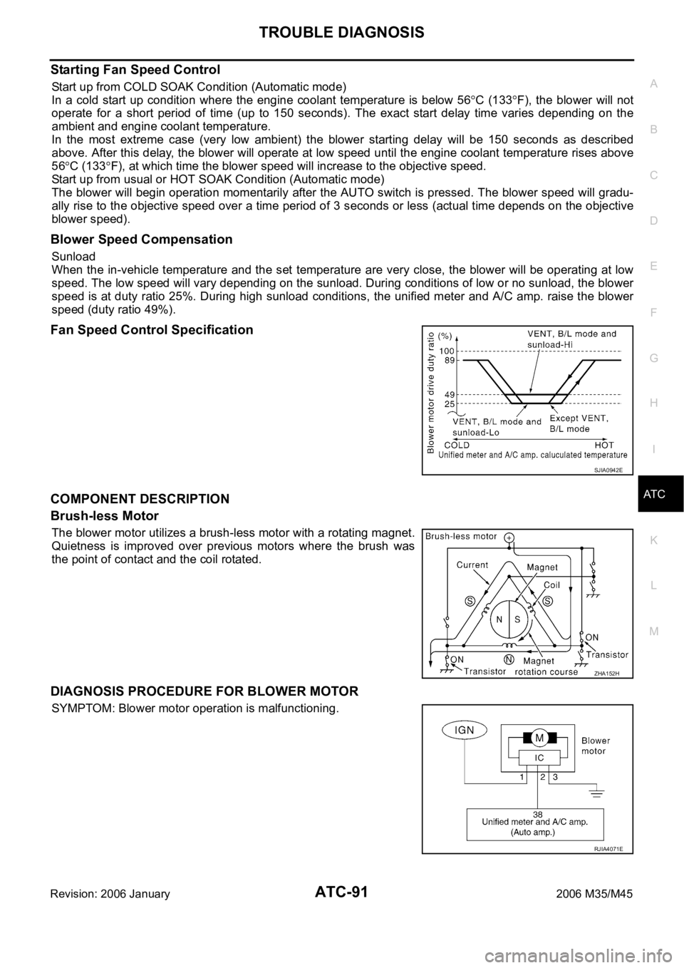
Fan Speed Control Specification
COMPONENT DESCRIPTION
Brush-less Motor
The blower motor utilizes a brush-less motor with a rotating magnet.
Quietness is improved over previous motors where the brush was
the point of contact and the coil rotated.
DIAGNOSIS PROCEDURE FOR BLOWER MOTOR
SYMPTOM: Blower motor operation is malfunctioning.
SJIA0942E
ZHA152H
RJIA4071E
Page 576 of 5621
INTAKE SENSOR
ATC-129
C
D
E
F
G
H
I
K
L
MA
B
AT C
Revision: 2006 January2006 M35/M45
INTAKE SENSORPFP:27723
Removal and InstallationNJS000H9
REMOVAL
1. Remove low-pressure pipe 1 and high-pressure pipe 2. Refer to ATC-162, "Removal and Installation of
Low-Pressure Pipe 1 and High-Pressure Pipe 2" .
CAUTION:
Cap or wrap the joint of the pipe with suitable material such as vinyl tape to avoid the entry of air.
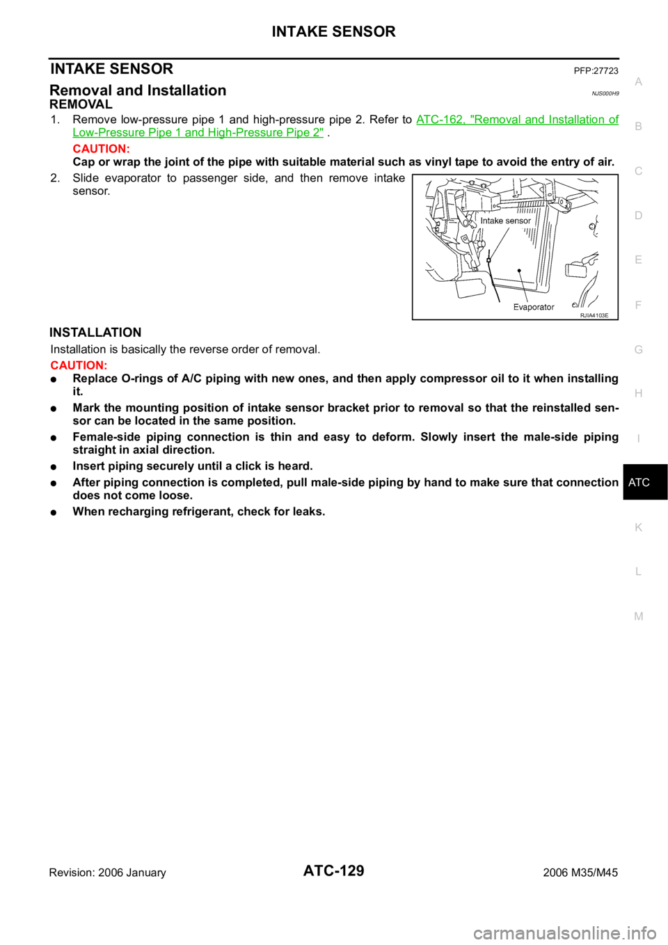
2. Slide evaporator to passenger side, and then remove intake
sensor.
INSTALLATION
Installation is basically the reverse order of removal.
CAUTION:
Replace O-rings of A/C piping with new ones, and then apply compressor oil to it when installing
it.
Mark the mounting position of intake sensor bracket prior to removal so that the reinstalled sen-
sor can be located in the same position.
Female-side piping connection is thin and easy to deform. Slowly insert the male-side piping
straight in axial direction.
Insert piping securely until a click is heard.
After piping connection is completed, pull male-side piping by hand to make sure that connection
does not come loose.
When recharging refrigerant, check for leaks.
RJIA4103E
Page 584 of 5621
HEATER & COOLING UNIT ASSEMBLY
ATC-137
C
D
E
F
G
H
I
K
L
MA
B
AT C
Revision: 2006 January2006 M35/M45
CAUTION:
Replace O-rings of A/C piping with new ones, and then apply compressor oil to it when installing
it.
Female-side piping connection is thin and easy to deform. Slowly insert the male-side piping
straight in axial direction.
Insert piping securely until a click is heard.
After piping connection is completed, pull male-side piping by hand to make sure that connection
does not come loose.
When recharging refrigerant, check for leaks.
NOTE:
When filling radiator with coolant, refer to CO-11, "Changing Engine Coolant" (VQ35DE) or CO-40,
"Changing Engine Coolant" (VK45DE).
Recharge the refrigerant.
Heater & cooling unit assembly mounting bolt
: 6.9 Nꞏm (0.7 kg-m, 61 in-lb)
Instrument stay mounting nut and bolt
: 12 Nꞏm (1.25 kg-m, 9 ft-lb)
Page 604 of 5621
REFRIGERANT LINES
ATC-157
C
D
E
F
G
H
I
K
L
MA
B
AT C
Revision: 2006 January2006 M35/M45
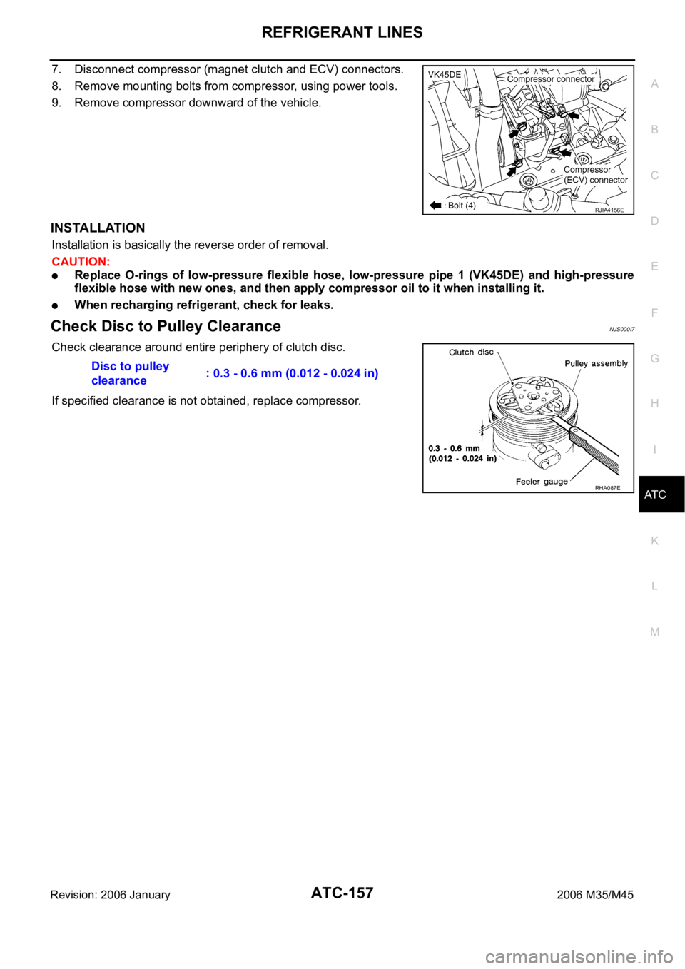
7. Disconnect compressor (magnet clutch and ECV) connectors.
8. Remove mounting bolts from compressor, using power tools.
9. Remove compressor downward of the vehicle.
INSTALLATION
Installation is basically the reverse order of removal.
CAUTION:
Replace O-rings of low-pressure flexible hose, low-pressure pipe 1 (VK45DE) and high-pressure
flexible hose with new ones, and then apply compressor oil to it when installing it.
When recharging refrigerant, check for leaks.
Check Disc to Pulley ClearanceNJS000I7
Check clearance around entire periphery of clutch disc.
If specified clearance is not obtained, replace compressor.
RJIA4156E
Disc to pulley
clearance: 0.3 - 0.6 mm (0.012 - 0.024 in)
RHA087E
Page 606 of 5621
REFRIGERANT LINES
ATC-159
C
D
E
F
G
H
I
K
L
MA
B
AT C
Revision: 2006 January2006 M35/M45
CAUTION:
Replace O-rings of low-pressure flexible hose and low-pressure pipe (VK45DE) with new ones,
and then apply compressor oil to it when installing it.
Female-side piping connection is thin and easy to deform. Slowly insert the male-side piping
straight in axial direction.
Insert piping securely until a click is heard.
After piping connection is completed, pull male-side piping by hand to make sure that connection
does not come loose.
When recharging refrigerant, check for leaks.
Removal and Installation of High-Pressure Flexible HoseNJS000HQ
REMOVAL
1. Use a refrigerant collecting equipment (for HFC-134a) to discharge the refrigerant.
2. Remove engine cover. Refer to EM-14, "
ENGINE ROOM COVER" (VQ35DE) or EM-173, "ENGINE
ROOM COVER" (VK45DE).
3. Remove air cleaner case and air duct. Refer to EM-17, "
AIR CLEANER AND AIR DUCT" (VQ35DE) or
EM-177, "
AIR CLEANER AND AIR DUCT" (VK45DE).
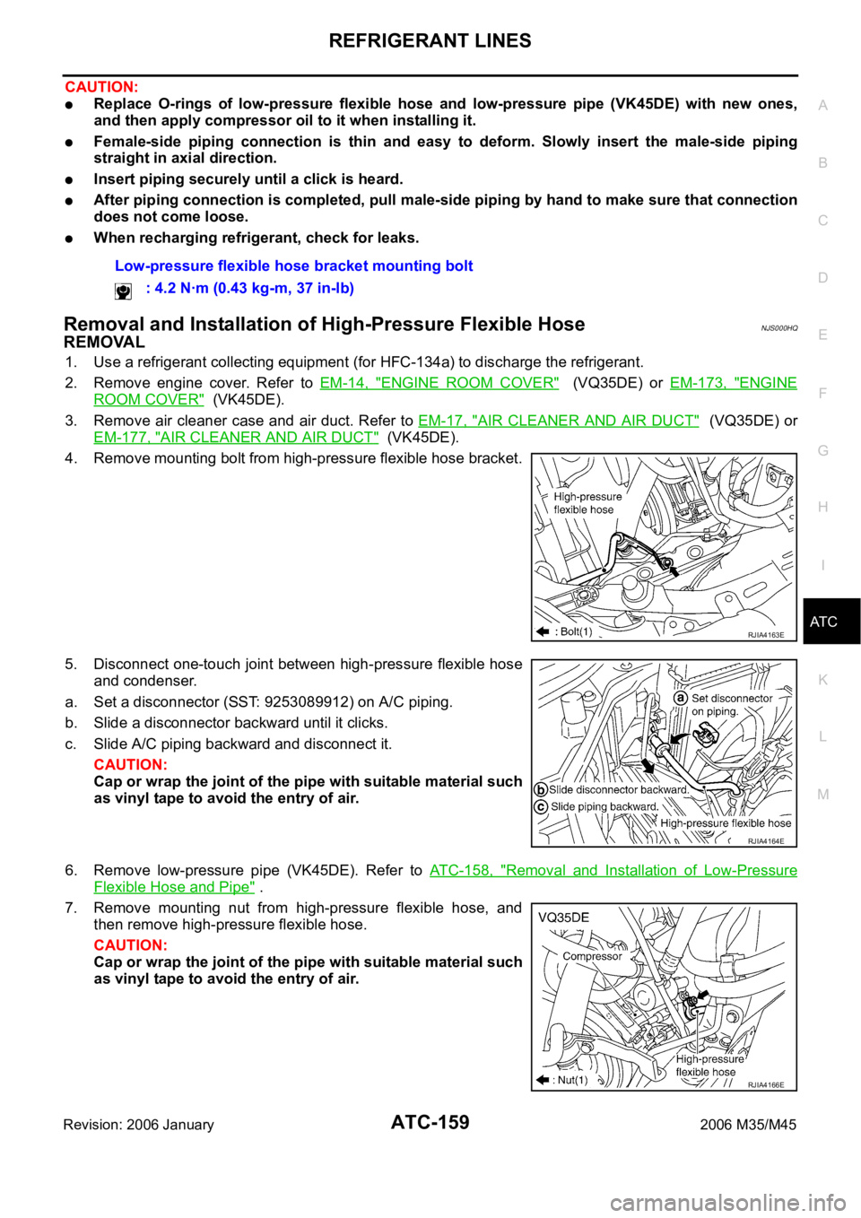
4. Remove mounting bolt from high-pressure flexible hose bracket.
5. Disconnect one-touch joint between high-pressure flexible hose
and condenser.
a. Set a disconnector (SST: 9253089912) on A/C piping.
b. Slide a disconnector backward until it clicks.
c. Slide A/C piping backward and disconnect it.
CAUTION:
Cap or wrap the joint of the pipe with suitable material such
as vinyl tape to avoid the entry of air.
6. Remove low-pressure pipe (VK45DE). Refer to ATC-158, "
Removal and Installation of Low-Pressure
Flexible Hose and Pipe" .
7. Remove mounting nut from high-pressure flexible hose, and
then remove high-pressure flexible hose.
CAUTION:
Cap or wrap the joint of the pipe with suitable material such
as vinyl tape to avoid the entry of air.Low-pressure flexible hose bracket mounting bolt
: 4.2 Nꞏm (0.43 kg-m, 37 in-lb)
RJIA4163E
RJIA4164E
RJIA4166E
Page 607 of 5621
ATC-160
REFRIGERANT LINES
Revision: 2006 January2006 M35/M45
INSTALLATION
Installation is basically the reverse order of removal.
CAUTION:
Replace O-rings of high-pressure flexible house with new ones, and then apply compressor oil to
it when installing it.
Female-side piping connection is thin and easy to deform. Slowly insert the male-side piping
straight in axial direction.
Insert piping securely until a click is heard.
After piping connection is completed, pull male-side piping by hand to make sure that connection
does not come loose.
When recharging refrigerant, check for leaks.
Removal and Installation of High-Pressure Pipe 1 (Engine Compartment)NJS000HR
REMOVAL
1. Remove low-pressure flexible hose. Refer to ATC-158, "Removal and Installation of Low-Pressure Flexi-
ble Hose and Pipe" .
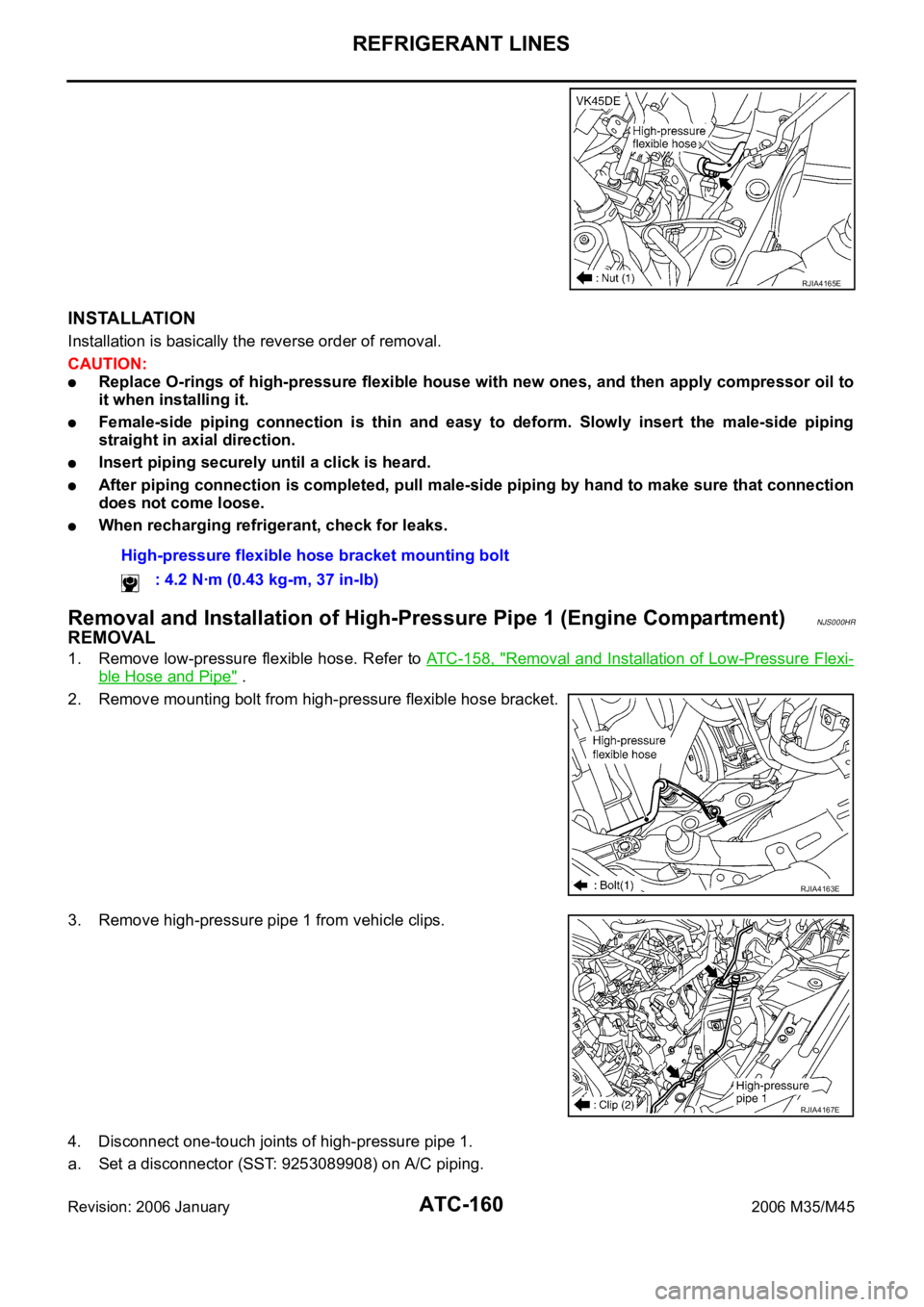
2. Remove mounting bolt from high-pressure flexible hose bracket.
3. Remove high-pressure pipe 1 from vehicle clips.
4. Disconnect one-touch joints of high-pressure pipe 1.
a. Set a disconnector (SST: 9253089908) on A/C piping.
RJIA4165E
High-pressure flexible hose bracket mounting bolt
: 4.2 Nꞏm (0.43 kg-m, 37 in-lb)
RJIA4163E
RJIA4167E
Page 608 of 5621
REFRIGERANT LINES
ATC-161
C
D
E
F
G
H
I
K
L
MA
B
AT C
Revision: 2006 January2006 M35/M45
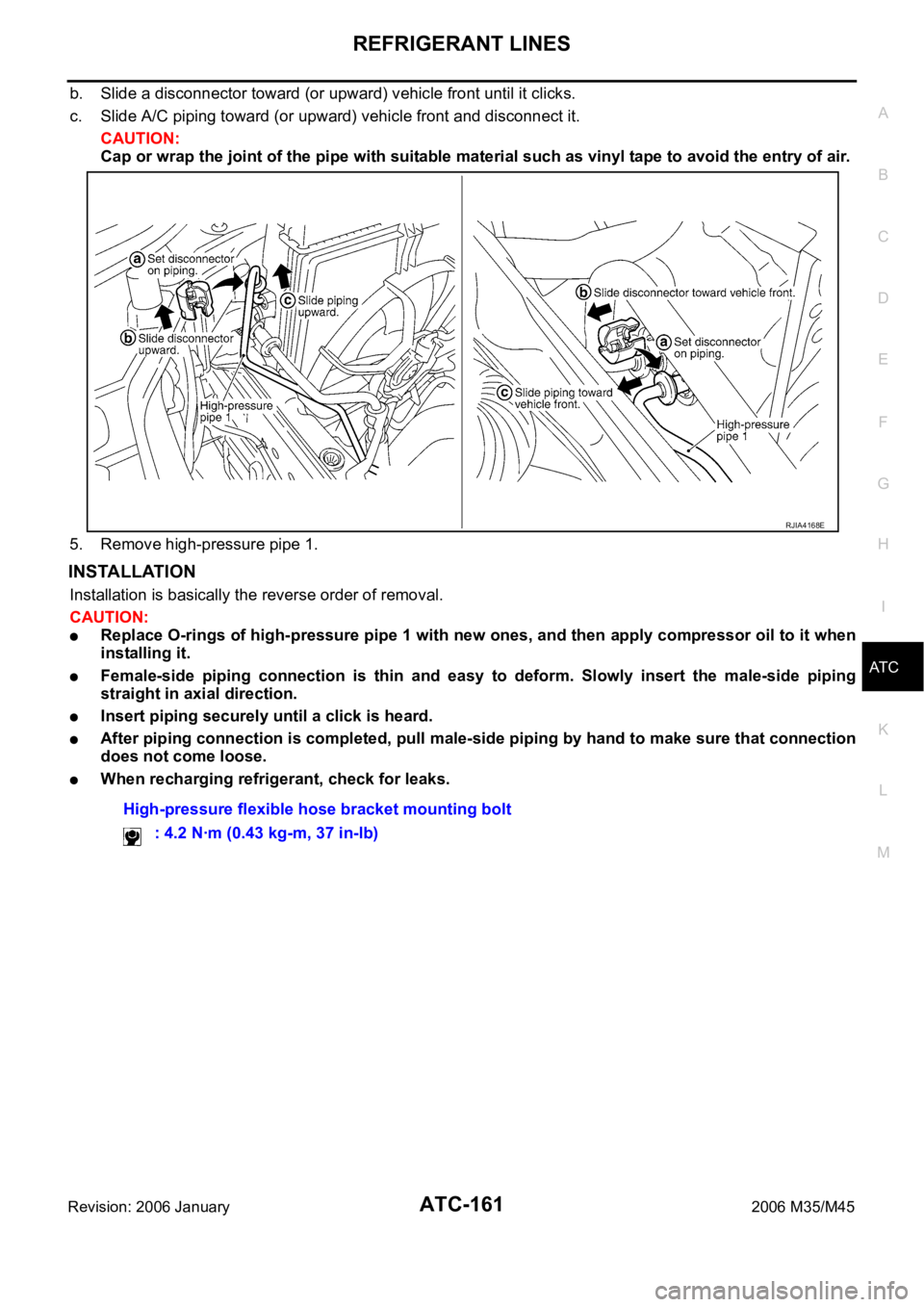
b. Slide a disconnector toward (or upward) vehicle front until it clicks.
c. Slide A/C piping toward (or upward) vehicle front and disconnect it.
CAUTION:
Cap or wrap the joint of the pipe with suitable material such as vinyl tape to avoid the entry of air.
5. Remove high-pressure pipe 1.
INSTALLATION
Installation is basically the reverse order of removal.
CAUTION:
Replace O-rings of high-pressure pipe 1 with new ones, and then apply compressor oil to it when
installing it.
Female-side piping connection is thin and easy to deform. Slowly insert the male-side piping
straight in axial direction.
Insert piping securely until a click is heard.
After piping connection is completed, pull male-side piping by hand to make sure that connection
does not come loose.
When recharging refrigerant, check for leaks.
RJIA4168E
High-pressure flexible hose bracket mounting bolt
: 4.2 Nꞏm (0.43 kg-m, 37 in-lb)
Page 610 of 5621
REFRIGERANT LINES
ATC-163
C
D
E
F
G
H
I
K
L
MA
B
AT C
Revision: 2006 January2006 M35/M45
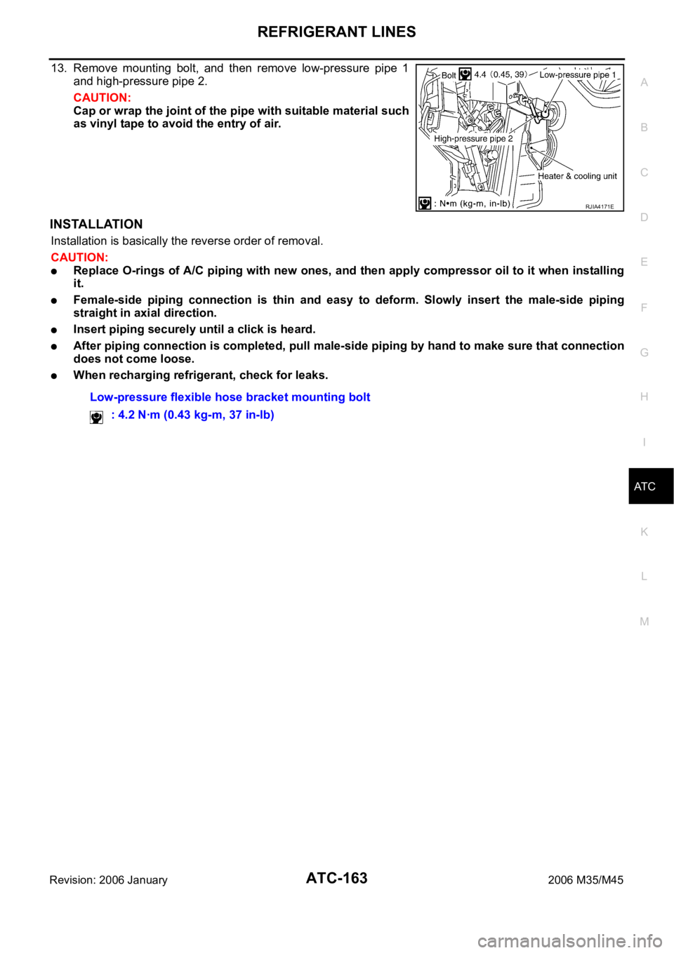
13. Remove mounting bolt, and then remove low-pressure pipe 1
and high-pressure pipe 2.
CAUTION:
Cap or wrap the joint of the pipe with suitable material such
as vinyl tape to avoid the entry of air.
INSTALLATION
Installation is basically the reverse order of removal.
CAUTION:
Replace O-rings of A/C piping with new ones, and then apply compressor oil to it when installing
it.
Female-side piping connection is thin and easy to deform. Slowly insert the male-side piping
straight in axial direction.
Insert piping securely until a click is heard.
After piping connection is completed, pull male-side piping by hand to make sure that connection
does not come loose.
When recharging refrigerant, check for leaks.
RJIA4171E
Low-pressure flexible hose bracket mounting bolt
: 4.2 Nꞏm (0.43 kg-m, 37 in-lb)
Page 612 of 5621
REFRIGERANT LINES
ATC-165
C
D
E
F
G
H
I
K
L
MA
B
AT C
Revision: 2006 January2006 M35/M45
INSTALLATION
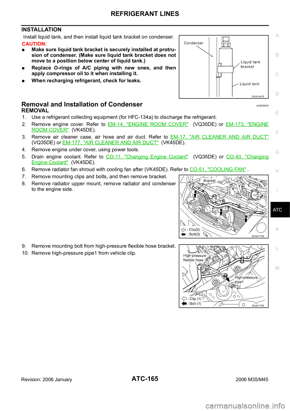
Install liquid tank, and then install liquid tank bracket on condenser.
CAUTION:
Make sure liquid tank bracket is securely installed at protru-
sion of condenser. (Make sure liquid tank bracket does not
move to a position below center of liquid tank.)
Replace O-rings of A/C piping with new ones, and then
apply compressor oil to it when installing it.
When recharging refrigerant, check for leaks.
Removal and Installation of CondenserNJS000HU
REMOVAL
1. Use a refrigerant collecting equipment (for HFC-134a) to discharge the refrigerant.
2. Remove engine cover. Refer to EM-14, "
ENGINE ROOM COVER" (VQ35DE) or EM-173, "ENGINE
ROOM COVER" (VK45DE).
3. Remove air cleaner case, air hose and air duct. Refer to EM-17, "
AIR CLEANER AND AIR DUCT"
(VQ35DE) or EM-177, "AIR CLEANER AND AIR DUCT" (VK45DE).
4. Remove engine under cover, using power tools.
5. Drain engine coolant. Refer to CO-11, "
Changing Engine Coolant" (VQ35DE) or CO-40, "Changing
Engine Coolant" (VK45DE).
6. Remove radiator fan shroud with cooling fan after (VK45DE). Refer to CO-51, "
COOLING FAN" .
7. Remove mounting clips and bolts, and then remove bracket.
8. Remove radiator upper mount, remove radiator and condenser
to the engine side.
9. Remove mounting bolt from high-pressure flexible hose bracket.
10. Remove high-pressure pipe1 from vehicle clip.
RJIA1441E
RJIA4173E
RJIA4174E