check INFINITI M35 2006 Factory Service Manual
[x] Cancel search | Manufacturer: INFINITI, Model Year: 2006, Model line: M35, Model: INFINITI M35 2006Pages: 5621, PDF Size: 65.56 MB
Page 5040 of 5621
SUNROOF
RF-27
C
D
E
F
G
H
J
K
L
MA
B
RF
Revision: 2006 January2006 M35/M45
SUNROOF UNIT
Removal
CAUTION:
Always work with a helper.
When taking sunroof unit out, use clothes to protect the seats and trim from damage.
After installing the sunroof unit and glass lid, be sure to carry out the leak test and check that
there is no malfunction.
1. Remove the headlining. Refer to EI-52, "
HEADLINING" .
2. Disconnect drain hoses.
3. Tilt up glass lid, and then remove glass lid.
4. Remove sunroof motor assembly mounting screws. Disconnect connector from sunroof motor assembly
and then remove sunroof motor assembly.
CAUTION:
Before removing sunroof motor, make sure that sunroof lid is fully closed.
After removing sunroof motor, do not attempt to rotate sunroof motor assembly as a single unit.
5. Remove nuts from the front end and side rail.
6. Remove front sunroof bracket bolts.
7. Remove rear sunroof bracket bolts, and then remove sunroof unit assembly from roof panel.
8. Remove sunroof unit assembly through the passenger compartment while being careful not to damage
the seats and trim.
Installation
1. Temporarily tighten the mounting bolts to the rear sunroof brackets (RH/LH).
2. Bring sunroof unit into passenger compartment, and then place the rear end of the rail onto the rear sun-
roof brackets.
3. Temporarily tighten the mounting nuts to the front end of sunroof unit assembly.
4. Tighten the installation points diagonally excluding the installation point of the sunroof bracket around the
roof opening.
5. Tighten the front sunroof bracket bolts of the vehicle side, and then tighten the bolt of the rail side.
6. Tighten the rear sunroof bracket bolts of the vehicle side, and then tighten the bolt of the rail side.
7. Tighten the mounting nuts to the front end and side rail.
8. Move the sunroof motor assembly laterally by little by little so that the gear is completely engaged into the
wire on the sunroof unit assembly and mounting surface becomes parallel. Then secure the sunroof motor
assembly with screws.
CAUTION:
Before installing the sunroof motor assembly, be sure to the place the link and wire assembly in
the symmetrical and fully closed position.
9. Install glass lid.
NOTE:
After installation, carry out fitting adjustment.
10. Connect drain hoses.
11. Install headlining. Refer to EI-52, "
HEADLINING" .
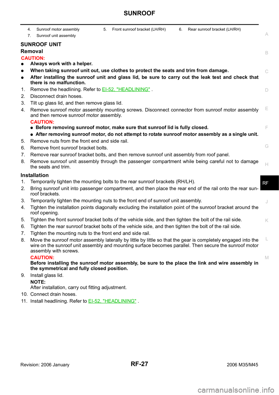
4. Sunroof motor assembly 5. Front sunroof bracket (LH/RH) 6. Rear sunroof bracket (LH/RH)
7. Sunroof unit assembly
Page 5044 of 5621
RFD-1
REAR FINAL DRIVE
D DRIVELINE/AXLE
CONTENTS
C
E
F
G
H
I
J
K
L
M
SECTION RFD
A
B
RFD
Revision: 2006 January2006 M35/M45
REAR FINAL DRIVE
PRECAUTIONS .......................................................... 2
Service Notice or Precautions .................................. 2
PREPARATION ........................................................... 3
Special Service Tools ............................................... 3
Commercial Service Tools ........................................ 6
NOISE, VIBRATION AND HARSHNESS (NVH)
TROUBLESHOOTING ................................................ 7
NVH Troubleshooting Chart ..................................... 7
DESCRIPTION ............................................................ 8
Cross-Sectional View ............................................... 8
DIFFERENTIAL GEAR OIL ........................................ 9
Changing Differential Gear Oil ................................. 9
DRAINING ............................................................. 9
FILLING ................................................................. 9
Checking Differential Gear Oil .................................. 9
OIL LEAKAGE AND OIL LEVEL ........................... 9
FRONT OIL SEAL .................................................
... 10
Removal and Installation ........................................ 10
IDENTIFICATION STAMP OF REPLACEMENT
FREQUENCY OF FRONT OIL SEAL ................. 10
REMOVAL ........................................................
... 10
INSTALLATION ................................................... 12
SIDE OIL SEAL ........................................................ 14
Removal and Installation ........................................ 14
REMOVAL ........................................................
... 14
INSTALLATION ................................................... 14REAR FINAL DRIVE ASSEMBLY ............................ 16
Removal and Installation ........................................ 16
COMPONENTS ................................................... 16
REMOVAL ........................................................
... 16
INSTALLATION ................................................... 17
Disassembly and Assembly .................................... 18
COMPONENTS ................................................... 18
ASSEMBLY INSPECTION AND ADJUSTMENT ... 19
DISASSEMBLY ................................................... 22
INSPECTION AFTER DISASSEMBLY ................ 26
ADJUSTMENT AND SELECTION OF ADJUST-
ING WASHERS ................................................... 26
ASSEMBLY ......................................................... 31
SERVICE DATA AND SPECIFICATIONS (SDS) ...... 37
General Specifications ......................................... ... 37
Inspection and Adjustment ..................................... 37
DRIVE GEAR RUNOUT ...................................... 37
DIFFERENTIAL SIDE GEAR CLEARANCE ....... 37
PRELOAD TORQUE ........................................... 37
BACKLASH ......................................................... 37
COMPANION FLANGE RUNOUT ....................... 37
SELECTIVE PARTS ............................................ 38
Page 5045 of 5621

RFD-2
PRECAUTIONS
Revision: 2006 January2006 M35/M45
PRECAUTIONSPFP:00001
Service Notice or PrecautionsNDS000EY
Check for the correct installation status prior to removal or disassembly. If matching marks are required,
be certain they do not interfere with the function of the parts when applied.
Overhaul should be done in a clean work area, it is preferable to work in dustproof area.
Before disassembly, using steam or white gasoline, completely remove sand and mud from the exterior of
the unit, preventing them from entering into the unit during disassembly or assembly.
Check appearance of the disassembled parts for damage, deformation, and unusual wear. Replace them
with a new ones if necessary.
Gaskets, seals and O-rings should be replaced any time when the unit is disassembled.
In principle, tighten bolts or nuts gradually in several steps working diagonally from inside to outside. If
tightening sequence is specified, observe it.
Clean and flush the parts sufficiently and blow-dry them.
Be careful not to damage sliding surfaces and mating surfaces.
When applying sealant, remove the old sealant from the mounting surface; then remove any moisture, oil,
and foreign materials from the application and mounting surfaces.
Always use shop paper for cleaning the inside of components.
Avoid using cotton gloves or shop rags to prevent entering of lint.
During assembly, observe the specified tightening torque, and apply new gear oil, petroleum jelly, or multi-
purpose grease as specified for each vehicle, if necessary.
Page 5050 of 5621
NOISE, VIBRATION AND HARSHNESS (NVH) TROUBLESHOOTING
RFD-7
C
E
F
G
H
I
J
K
L
MA
B
RFD
Revision: 2006 January2006 M35/M45
NOISE, VIBRATION AND HARSHNESS (NVH) TROUBLESHOOTINGPFP:00003
NVH Troubleshooting ChartNDS000F1
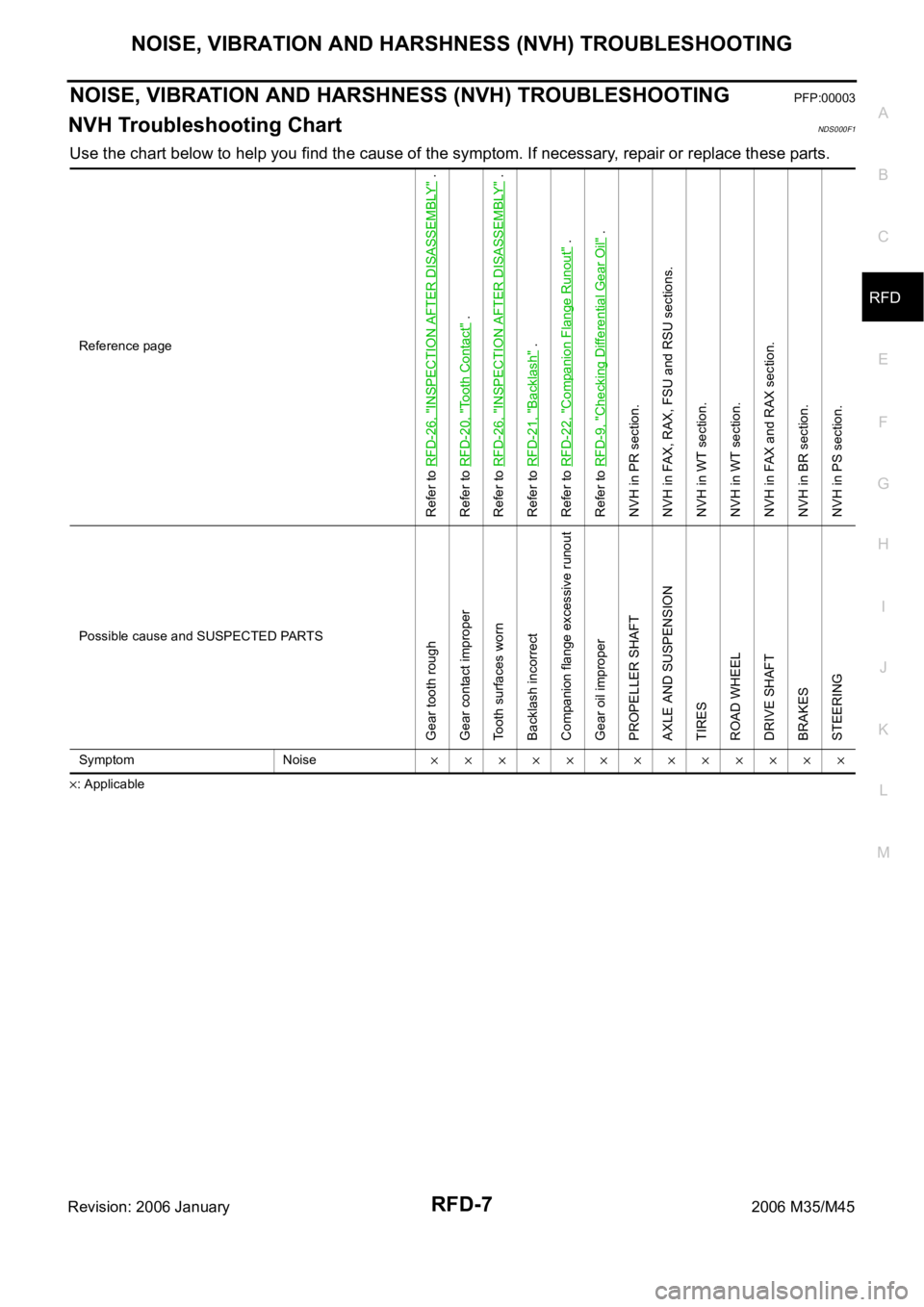
Use the chart below to help you find the cause of the symptom. If necessary, repair or replace these parts.
: ApplicableReference page
Refer to RFD-26, "
INSPECTION AFTER DISASSEMBLY
" .
Refer to RFD-20, "
Tooth Contact
" .
Refer to RFD-26, "
INSPECTION AFTER DISASSEMBLY
" .
Refer to RFD-21, "
Backlash
" .
Refer to RFD-22, "
Companion Flange Runout
" .
Refer to RFD-9, "
Checking Differential Gear Oil
" .
NVH in PR section.
NVH in FAX, RAX, FSU and RSU sections.
NVH in WT section.
NVH in WT section.
NVH in FAX and RAX section.
NVH in BR section.
NVH in PS section.
Possible cause and SUSPECTED PARTS
Gear tooth rough
Gear contact improper
Tooth surfaces worn
Backlash incorrect
Companion flange excessive runout
Gear oil improper
PROPELLER SHAFT
AXLE AND SUSPENSION
TIRES
ROAD WHEEL
DRIVE SHAFT
BRAKES
STEERING
Symptom Noise
Page 5052 of 5621
DIFFERENTIAL GEAR OIL
RFD-9
C
E
F
G
H
I
J
K
L
MA
B
RFD
Revision: 2006 January2006 M35/M45
DIFFERENTIAL GEAR OILPFP:KLD30
Changing Differential Gear OilNDS000F3
DRAINING
1. Stop engine.
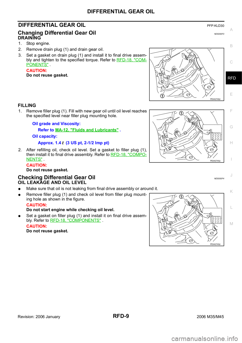
2. Remove drain plug (1) and drain gear oil.
3. Set a gasket on drain plug (1) and install it to final drive assem-
bly and tighten to the specified torque. Refer to RFD-18, "
COM-
PONENTS" .
CAUTION:
Do not reuse gasket.
FILLING
1. Remove filler plug (1). Fill with new gear oil until oil level reaches
the specified level near filler plug mounting hole.
2. After refilling oil, check oil level. Set a gasket to filler plug (1),
then install it to final drive assembly. Refer to RFD-18, "
COMPO-
NENTS" .
CAUTION:
Do not reuse gasket.
Checking Differential Gear OilNDS000F4
OIL LEAKAGE AND OIL LEVEL
Make sure that oil is not leaking from final drive assembly or around it.
Remove filler plug (1) and check oil level from filler plug mount-
ing hole as shown in the figure.
CAUTION:
Do not start engine while checking oil level.
Set a gasket on filler plug (1) and install it on final drive assem-
bly. Refer to RFD-18, "
COMPONENTS" .
CAUTION:
Do not reuse gasket.
PDIA0748J
Oil grade and Viscosity:
Refer to MA-12, "
Fluids and Lubricants" .
Oil capacity:
Approx. 1.4 (3 US pt, 2-1/2 Imp pt)
PDIA0749J
PDIA0749J
Page 5056 of 5621
FRONT OIL SEAL
RFD-13
C
E
F
G
H
I
J
K
L
MA
B
RFD
Revision: 2006 January2006 M35/M45
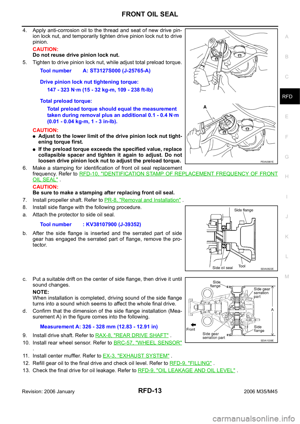
4. Apply anti-corrosion oil to the thread and seat of new drive pin-
ion lock nut, and temporarily tighten drive pinion lock nut to drive
pinion.
CAUTION:
Do not reuse drive pinion lock nut.
5. Tighten to drive pinion lock nut, while adjust total preload torque.
CAUTION:
Adjust to the lower limit of the drive pinion lock nut tight-
ening torque first.
If the preload torque exceeds the specified value, replace
collapsible spacer and tighten it again to adjust. Do not
loosen drive pinion lock nut to adjust the preload torque.
6. Make a stamping for identification of front oil seal replacement
frequency. Refer to RFD-10, "
IDENTIFICATION STAMP OF REPLACEMENT FREQUENCY OF FRONT
OIL SEAL" .
CAUTION:
Be sure to make a stamping after replacing front oil seal.
7. Install propeller shaft. Refer to PR-8, "
Removal and Installation" .
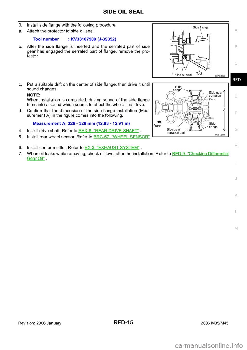
8. Install side flange with the following procedure.
a. Attach the protector to side oil seal.
b. After the side flange is inserted and the serrated part of side
gear has engaged the serrated part of flange, remove the pro-
tector.
c. Put a suitable drift on the center of side flange, then drive it until
sound changes.
NOTE:
When installation is completed, driving sound of the side flange
turns into a sound which seems to affect the whole final drive.
d. Confirm that the dimension of the side flange installation (Mea-
surement A) in the figure comes into the following.
9. Install drive shaft. Refer to RAX-8, "
REAR DRIVE SHAFT" .
10. Install rear wheel sensor. Refer to BRC-57, "
WHEEL SENSOR"
.
11. Install center muffler. Refer to EX-3, "
EXHAUST SYSTEM" .
12. Refill gear oil to the final drive and check oil level. Refer to RFD-9, "
FILLING" .
13. Check the final drive for oil leakage. Refer to RFD-9, "
OIL LEAKAGE AND OIL LEVEL" . Tool number A: ST3127S000 (J-25765-A)
Drive pinion lock nut tightening torque:
147 - 323 Nꞏm (15 - 32 kg-m, 109 - 238 ft-lb)
Total preload torque:
Total preload torque should equal the measurement
taken during removal plus an additional 0.1 - 0.4 Nꞏm
(0.01 - 0.04 kg-m, 1 - 3 in-lb).
Tool number : KV38107900 (J-39352)
PDIA0981E
SDIA0822E
Measurement A: 326 - 328 mm (12.83 - 12.91 in)
SDIA1039E
Page 5058 of 5621
SIDE OIL SEAL
RFD-15
C
E
F
G
H
I
J
K
L
MA
B
RFD
Revision: 2006 January2006 M35/M45
3. Install side flange with the following procedure.
a. Attach the protector to side oil seal.
b. After the side flange is inserted and the serrated part of side
gear has engaged the serrated part of flange, remove the pro-
tector.
c. Put a suitable drift on the center of side flange, then drive it until
sound changes.
NOTE:
When installation is completed, driving sound of the side flange
turns into a sound which seems to affect the whole final drive.
d. Confirm that the dimension of the side flange installation (Mea-
surement A) in the figure comes into the following.
4. Install drive shaft. Refer to RAX-8, "
REAR DRIVE SHAFT" .
5. Install rear wheel sensor. Refer to BRC-57, "
WHEEL SENSOR"
.
6. Install center muffler. Refer to EX-3, "
EXHAUST SYSTEM" .
7. When oil leaks while removing, check oil level after the installation. Refer to RFD-9, "
Checking Differential
Gear Oil" . Tool number : KV38107900 (J-39352)
SDIA0822E
Measurement A: 326 - 328 mm (12.83 - 12.91 in)
SDIA1039E
Page 5060 of 5621
REAR FINAL DRIVE ASSEMBLY
RFD-17
C
E
F
G
H
I
J
K
L
MA
B
RFD
Revision: 2006 January2006 M35/M45
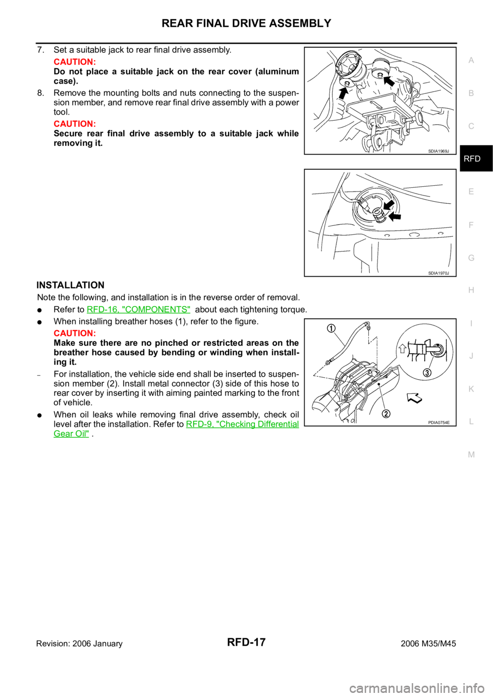
7. Set a suitable jack to rear final drive assembly.
CAUTION:
Do not place a suitable jack on the rear cover (aluminum
case).
8. Remove the mounting bolts and nuts connecting to the suspen-
sion member, and remove rear final drive assembly with a power
tool.
CAUTION:
Secure rear final drive assembly to a suitable jack while
removing it.
INSTALLATION
Note the following, and installation is in the reverse order of removal.
Refer to RFD-16, "COMPONENTS" about each tightening torque.
When installing breather hoses (1), refer to the figure.
CAUTION:
Make sure there are no pinched or restricted areas on the
breather hose caused by bending or winding when install-
ing it.
–For installation, the vehicle side end shall be inserted to suspen-
sion member (2). Install metal connector (3) side of this hose to
rear cover by inserting it with aiming painted marking to the front
of vehicle.
When oil leaks while removing final drive assembly, check oil
level after the installation. Refer to RFD-9, "
Checking Differential
Gear Oil" .
SDIA1969J
SDIA1970J
PDIA0754E
Page 5062 of 5621
REAR FINAL DRIVE ASSEMBLY
RFD-19
C
E
F
G
H
I
J
K
L
MA
B
RFD
Revision: 2006 January2006 M35/M45
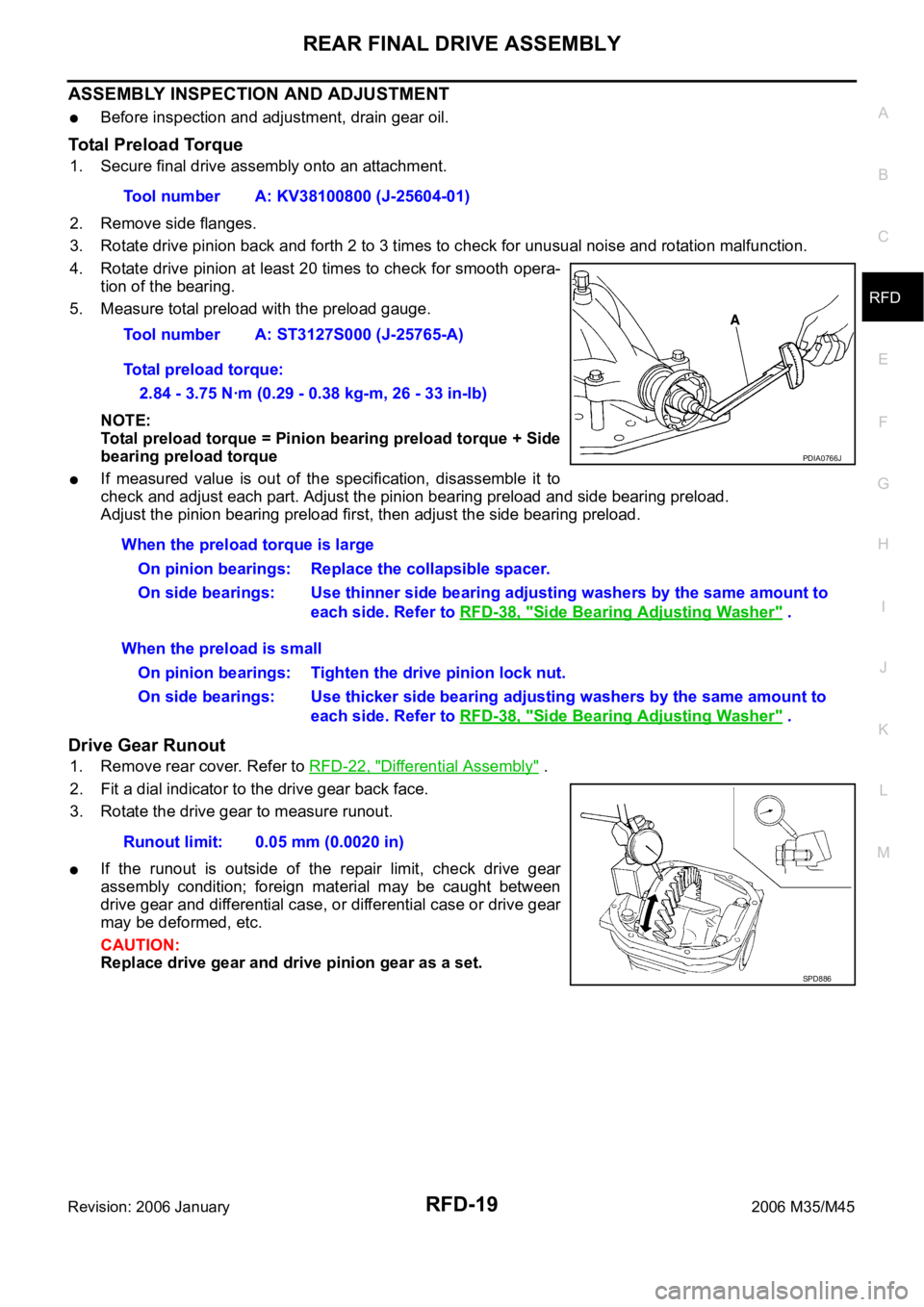
ASSEMBLY INSPECTION AND ADJUSTMENT
Before inspection and adjustment, drain gear oil.
Total Preload Torque
1. Secure final drive assembly onto an attachment.
2. Remove side flanges.
3. Rotate drive pinion back and forth 2 to 3 times to check for unusual noise and rotation malfunction.
4. Rotate drive pinion at least 20 times to check for smooth opera-
tion of the bearing.
5. Measure total preload with the preload gauge.
NOTE:
Total preload torque = Pinion bearing preload torque + Side
bearing preload torque
If measured value is out of the specification, disassemble it to
check and adjust each part. Adjust the pinion bearing preload and side bearing preload.
Adjust the pinion bearing preload first, then adjust the side bearing preload.
Drive Gear Runout
1. Remove rear cover. Refer to RFD-22, "Differential Assembly" .
2. Fit a dial indicator to the drive gear back face.
3. Rotate the drive gear to measure runout.
If the runout is outside of the repair limit, check drive gear
assembly condition; foreign material may be caught between
drive gear and differential case, or differential case or drive gear
may be deformed, etc.
CAUTION:
Replace drive gear and drive pinion gear as a set.Tool number A: KV38100800 (J-25604-01)
Tool number A: ST3127S000 (J-25765-A)
Total preload torque:
2.84 - 3.75 Nꞏm (0.29 - 0.38 kg-m, 26 - 33 in-lb)
PDIA0766J
When the preload torque is large
On pinion bearings: Replace the collapsible spacer.
On side bearings: Use thinner side bearing adjusting washers by the same amount to
each side. Refer to RFD-38, "
Side Bearing Adjusting Washer" .
When the preload is small
On pinion bearings: Tighten the drive pinion lock nut.
On side bearings: Use thicker side bearing adjusting washers by the same amount to
each side. Refer to RFD-38, "
Side Bearing Adjusting Washer" .
Runout limit: 0.05 mm (0.0020 in)
SPD886
Page 5063 of 5621
RFD-20
REAR FINAL DRIVE ASSEMBLY
Revision: 2006 January2006 M35/M45
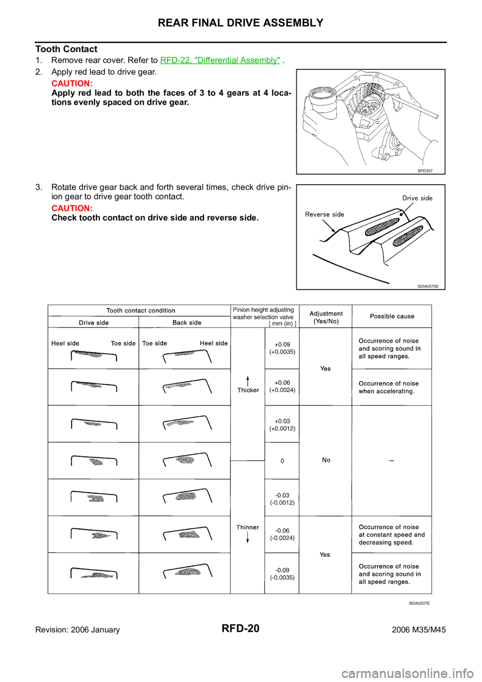
Tooth Contact
1. Remove rear cover. Refer to RFD-22, "Differential Assembly" .
2. Apply red lead to drive gear.
CAUTION:
Apply red lead to both the faces of 3 to 4 gears at 4 loca-
tions evenly spaced on drive gear.
3. Rotate drive gear back and forth several times, check drive pin-
ion gear to drive gear tooth contact.
CAUTION:
Check tooth contact on drive side and reverse side.
SPD357
SDIA0570E
SDIA0207E