check INFINITI M35 2006 Factory Service Manual
[x] Cancel search | Manufacturer: INFINITI, Model Year: 2006, Model line: M35, Model: INFINITI M35 2006Pages: 5621, PDF Size: 65.56 MB
Page 5126 of 5621
![INFINITI M35 2006 Factory Service Manual PRE-CRASH SEAT BELT
SB-27
C
D
E
F
G
I
J
K
L
MA
B
SB
Revision: 2006 January2006 M35/M45
Pre-Crash Seat Belt Motor RH Circuit Check [B2451]NHS0008F
1. CHECK RH SEAT BELT MOTOR CIRCUIT
With CONSULT-II
S INFINITI M35 2006 Factory Service Manual PRE-CRASH SEAT BELT
SB-27
C
D
E
F
G
I
J
K
L
MA
B
SB
Revision: 2006 January2006 M35/M45
Pre-Crash Seat Belt Motor RH Circuit Check [B2451]NHS0008F
1. CHECK RH SEAT BELT MOTOR CIRCUIT
With CONSULT-II
S](/img/42/57023/w960_57023-5125.png)
PRE-CRASH SEAT BELT
SB-27
C
D
E
F
G
I
J
K
L
MA
B
SB
Revision: 2006 January2006 M35/M45
Pre-Crash Seat Belt Motor RH Circuit Check [B2451]NHS0008F
1. CHECK RH SEAT BELT MOTOR CIRCUIT
With CONSULT-II
Select SELF-DIAG RESULTS” of CONSULT-II, and then make sure
that “SB MOTOR RH CIRC” is displayed.
Without CONSULT-II
When CONSULT-II is not used, omit this inspection, and then GO TO 2.
Displayed B2451?
Ye s > > G O T O 2 .
No >> Pre-crash seat belt motor RH circuit is OK.
2. CHECK RH SEAT BELT MOTOR HARNESS
1. Turn the ignition switch OFF.
2. Disconnect pre-crash seat belt control unit connector and pre-crash seat belt motor RH connector.
3. Check continuity between pre-crash seat belt control unit har-
ness connector and pre-crash seat belt motor RH harness con-
nector.
4. Check continuity between pre-crash seat belt control unit har-
ness connector and ground.
OK or NG
OK >> GO TO 3.
NG >> Repair or replace harness.
CONSULT-II display CONSULT-II display code
NO DTC –
SB MOTOR RH CIRC B2451
PHIA0767E
AB
Continuity Pre-crash seat
belt control unit
connectorTerminalPre-crash seat
belt motor RH
connectorTerminal
B1421
B82
Ye s
3 1
A
GroundContinuity
Pre-crash seat belt
control unit connectorTerminal
B1421
No
3
PHIA1140E
Page 5127 of 5621
SB-28
PRE-CRASH SEAT BELT
Revision: 2006 January2006 M35/M45
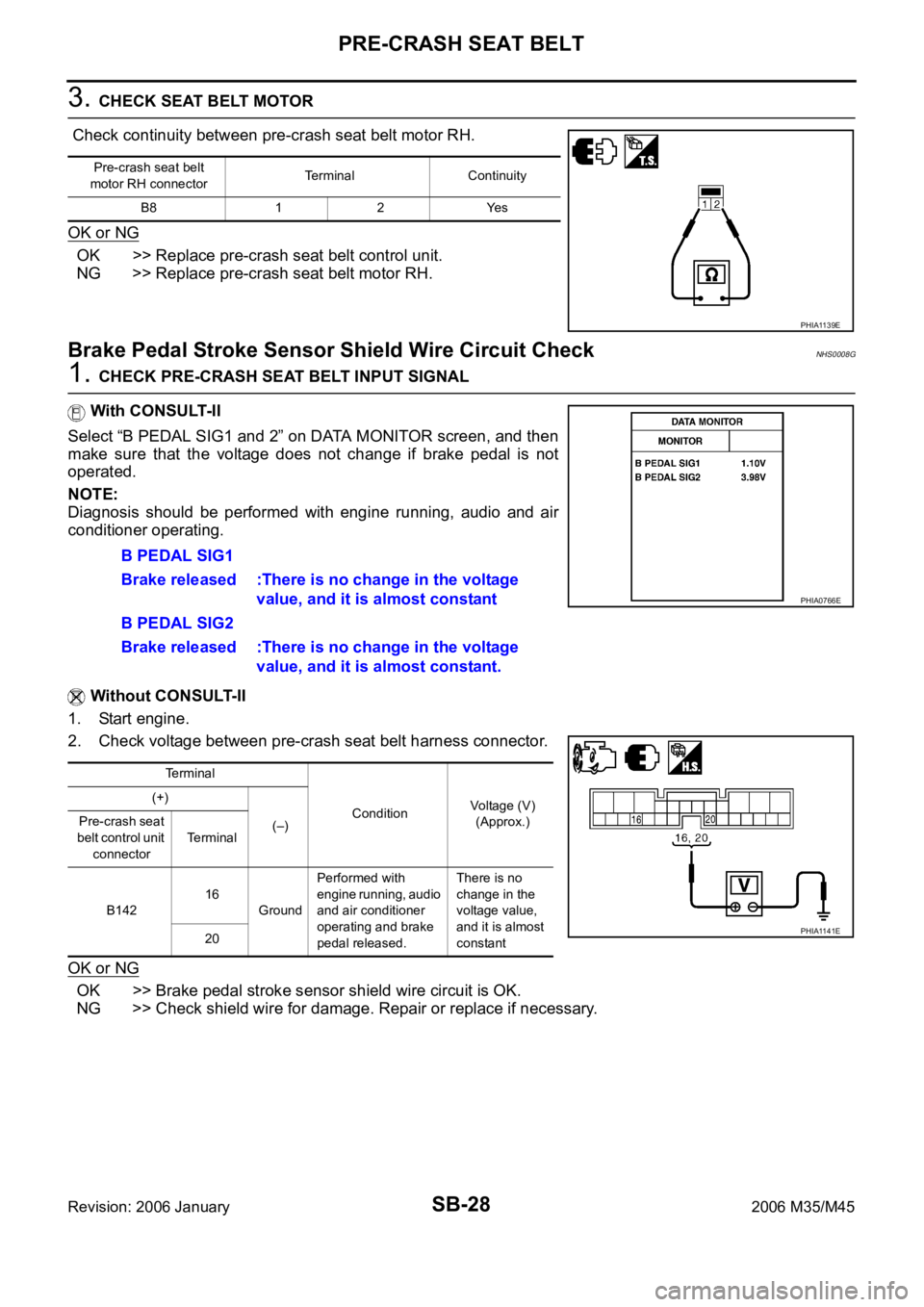
3. CHECK SEAT BELT MOTOR
Check continuity between pre-crash seat belt motor RH.
OK or NG
OK >> Replace pre-crash seat belt control unit.
NG >> Replace pre-crash seat belt motor RH.
Brake Pedal Stroke Sensor Shield Wire Circuit CheckNHS0008G
1. CHECK PRE-CRASH SEAT BELT INPUT SIGNAL
With CONSULT-II
Select “B PEDAL SIG1 and 2” on DATA MONITOR screen, and then
make sure that the voltage does not change if brake pedal is not
operated.
NOTE:
Diagnosis should be performed with engine running, audio and air
conditioner operating.
Without CONSULT-II
1. Start engine.
2. Check voltage between pre-crash seat belt harness connector.
OK or NG
OK >> Brake pedal stroke sensor shield wire circuit is OK.
NG >> Check shield wire for damage. Repair or replace if necessary.
Pre-crash seat belt
motor RH connectorTerminal Continuity
B8 1 2 Yes
PHIA1139E
B PEDAL SIG1
Brake released :There is no change in the voltage
value, and it is almost constant
B PEDAL SIG2
Brake released :There is no change in the voltage
value, and it is almost constant.
Terminal
ConditionVoltage (V)
(Approx.) (+)
(–) Pre-crash seat
belt control unit
connectorTerminal
B14216
GroundPerformed with
engine running, audio
and air conditioner
operating and brake
pedal released.There is no
change in the
voltage value,
and it is almost
constant 20
PHIA0766E
PHIA1141E
Page 5132 of 5621
SEAT BELTS
SB-33
C
D
E
F
G
I
J
K
L
MA
B
SB
Revision: 2006 January2006 M35/M45
INSTALLATION OF SEAT BELT BUCKLE
Install in the reverse order of removal.
Tighten by specified torque.
Seat Belt InspectionNHS0008L
AFTER A COLLISION
WAR NING :
Inspect all seat belt assemblies including retractors and attaching hardware after any collision.
NISSAN / INFINITI recommends that all seat belt assemblies in use during a collision be replaced
unless the collision was minor and the belts show no damage and continue to operate properly. Fail-
ure to do so could result in serious personal injury in an accident. Seat belt assemblies not in use dur-
ing a collision should also be replaced if either damage or improper operation is noted. Seat belt pre-
tensioned should be replaced even if the seat belts are not in use during a frontal collision in which
the air bags are deployed.
Replace any seat belt assembly (including anchor bolts) if:
The seat belt was in use at the time of a collision (except for minor collisions and the belts, retractors and
buckles show no damage and continue to operate properly).
The seat belt was damaged in an accident. (i.e. torn webbing, bent retractor or guide, etc.)
The seat belt attaching point was damaged in an accident. Inspect the seat belt attaching area for damage
or distortion and repair as necessary before installing a new seat belt assembly.
Anchor bolts are deformed or worn out.
The seat belt pre-tensioner should be replaced even if the seat belts are not in use during the collision in
which the air bags are deployed.
PRELIMINARY CHECKS
1. Check the seat belt warning lamp/chime for proper operation as follows:
a. Switch ignition ON. The seat belt warning lamp should illuminate. Also, the seat belt warning chime should
sound for about six seconds.
b. Fasten driver's seat belt. The seat belt warning lamp should go out and the chime (if sounding) should
stop.
2. If the air bag warning lamp is blinking, conduct self-diagnosis using CONSULT-II, and air bag warning
lamp. Refer to SRS-19, "
SRS Operation Check" .
3. Check that the seat belt retractor, seat belt anchor and buckle bolts are securely attached.
4. Check the shoulder seat belt guide and shoulder belt height adjuster for front seats. Ensure guide swivels
freely and that webbing lays flat and does not bind in guide. Ensure height adjuster operates properly and
holds securely.
5. Check retractor operation:
a. Fully extend the seat belt webbing and check for twists, tears or other damage.
b. Allow the seat belt to retract. Ensure that webbing returns smoothly and completely into the retractor. If
the seat belt does not return smoothly, wipe the inside of the loops with a clean paper cloth. Because dirt
built up in the loops of the upper anchors can cause the seat belts to retract slowly.
c. Fasten the seat belt. Check the seat belt returns smoothly and completely to the retractor. If the webbing
does not return smoothly, the cause may be an accumulation of dust or dirt. Use the “SEAT BELT TAPE
SET” and perform the following steps.
Inspect the front seat belt though-anchor
1. Pull the seat belt out to a length of 500 mm (19.69 in) or more.
2. Use a clip or other device to the fix the seat belt at the center pillar webbing opening.
3. Pass a thin wire though the though-anchor webbing opening. Hold both ends of the wire and pull it
tantly while moving it up and down several times along the webbing opening surface to move matter
stuck there.
4. Any dirt that can not be removed with the wire can be removed by cleaning the opening with a clean
cloth.
5. Apply tape at the point where the webbing contacts the though-anchor webbing opening. Tightening torque : 49.0 Nꞏm (5.0 kg-m, 36 ft-lb)
Page 5133 of 5621

SB-34
SEAT BELTS
Revision: 2006 January2006 M35/M45
NOTE:
Apply the tape so that there is no looseness or wrinkling.
6. Remove the clip fixing the seat belt and check that the webbing returns smoothly.
6. Repeat steps above as necessary to check the other seat belts.
SEAT BELT RETRACTOR ON-VEHICLE CHECK
Emergency Locking Retractors (ELR) and Automatic Locking Retractors (ALR)
NOTE:
All seat belt retractors are of the Emergency Locking Retractors (ELR) type. In an emergency (sudden stop)
the retractor will lock and prevent the webbing from extending any further. All 3-point type seat belt retractors
except the driver's seat belt also have an Automatic Locking Retractors (ALR) mode. The ALR mode (also
called child restraint mode) is used when installing child seats. The ALR mode is activated when the seat belt
is fully extended. When the webbing is then retracted partially, the ALR mode automatically locks the seat belt
in a specific position so the webbing cannot be extended any further. To cancel the ALR mode, allow the seat
belt to fully wind back into the retractor.
Check the seat belt retractors using the following test(s) to determine if a retractor assembly is operating prop-
erly.
ELR Function Stationary Check
Grasp the shoulder webbing and pull forward quickly. The retractor should lock and prevent the belt from
extending further.
ALR Function Stationary Check
1. Pull out entire length of seat belt from retractor until a click is heard.
2. Retract the webbing partially. A clicking noise should be heard as the webbing retracts indicating that the
retractor is in the Automatic Locking Retractors (ALR) mode.
3. Grasp the seat belt and try to pull out the retractor. The webbing must lock and not extend any further. If
NG, replace the retractor assembly.
4. Allow the entire length of the webbing to retract to cancel the automatic locking mode.
ELR Function Moving Check
WAR NING :
Perform the following test in a safe, open area clear of other vehicles and obstructions (for example, a
large, empty parking lot). Road surface must be paved and dry. DO NOT perform the following test on
wet or gravel roads or on public streets and highways. This could result in an accident and serious
personal injury. The driver and passenger must be prepared to brace themselves in the event the
retractor does not lock.
1. Fasten driver's seat belt. Buckle a passenger into the seat for the belt that is to be tested.
2. Proceed to the designated safe area.
3. Drive the vehicle at approximately 16 km/h (10 MPH). Notify any passengers of a pending sudden stop
and the driver and passenger must be prepared to brace themselves in the event the retractor does not
lock, apply brakes firmly and make a very hard stop.
During stop, seat belts should lock and not be extended. If the seat belt retractor assembly does not lock, per-
form the retractor off-vehicle check.
Page 5134 of 5621
SEAT BELTS
SB-35
C
D
E
F
G
I
J
K
L
MA
B
SB
Revision: 2006 January2006 M35/M45
SEAT BELT RETRACTOR OFF-VEHICLE CHECK (FRONT SEAT BELT)
1. Remove the seat belt retractor.
Remove the front seat belt assembly, refer to SB-30, "Removal and Installation of Front Seat Belt" .
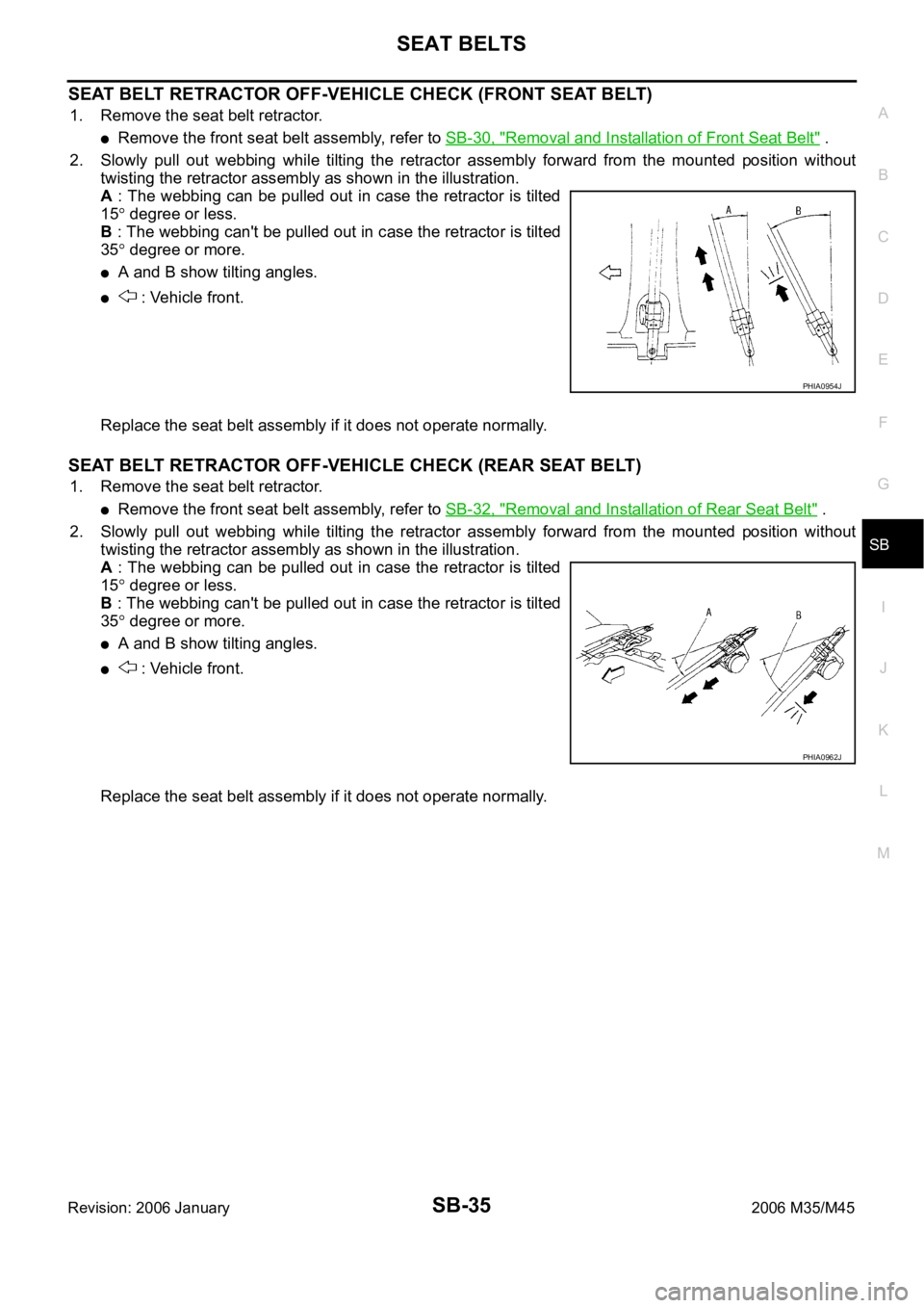
2. Slowly pull out webbing while tilting the retractor assembly forward from the mounted position without
twisting the retractor assembly as shown in the illustration.
A : The webbing can be pulled out in case the retractor is tilted
15
degree or less.
B : The webbing can't be pulled out in case the retractor is tilted
35
degree or more.
A and B show tilting angles.
: Vehicle front.
Replace the seat belt assembly if it does not operate normally.
SEAT BELT RETRACTOR OFF-VEHICLE CHECK (REAR SEAT BELT)
1. Remove the seat belt retractor.
Remove the front seat belt assembly, refer to SB-32, "Removal and Installation of Rear Seat Belt" .
2. Slowly pull out webbing while tilting the retractor assembly forward from the mounted position without
twisting the retractor assembly as shown in the illustration.
A : The webbing can be pulled out in case the retractor is tilted
15
degree or less.
B : The webbing can't be pulled out in case the retractor is tilted
35
degree or more.
A and B show tilting angles.
: Vehicle front.
Replace the seat belt assembly if it does not operate normally.
PHIA0954J
PHIA0962J
Page 5138 of 5621

SC-1
STARTING & CHARGING SYSTEM
K ELECTRICAL
CONTENTS
C
D
E
F
G
H
I
J
L
M
SECTION SC
A
B
SC
Revision: 2006 January2006 M35/M45
STARTING & CHARGING SYSTEM
PRECAUTIONS .......................................................... 2
Precautions for Supplemental Restraint System
(SRS) “AIR BAG” and “SEAT BELT PRE-TEN-
SIONER” .................................................................. 2
Precautions for Power Generation Voltage Variable
Control System ......................................................... 2
PREPARATION ........................................................... 3
Special Service Tools ............................................... 3
Commercial Service Tools ........................................ 3
BATTERY .................................................................... 4
How to Handle Battery ............................................. 4
METHODS OF PREVENTING OVER-DIS-
CHARGE ............................................................... 4
CHECKING ELECTROLYTE LEVEL .................... 5
SPECIFIC GRAVITY CHECK ............................... 5
CHARGING THE BATTERY ................................. 6
Trouble Diagnosis with Battery/Starting/Charging
System Tester (Battery) ............................................ 7
DIAGNOSTIC RESULT ITEM CHART .................. 8
Removal and Installation .......................................... 9
REMOVAL ........................................................
..... 9
INSTALLATION ..................................................... 9
STARTING SYSTEM ................................................ 10
System Description ................................................ 10
Wiring Diagram — START — .................................. 11
VQ35DE ENGINE MODELS ................................ 11
VK45DE ENGINE MODELS ............................... 12
Trouble Diagnosis with Battery/Starting/Charging
System Tester (Starting) ......................................... 13
DIAGNOSTIC RESULT ITEM CHART ................ 13
WORK FLOW ...................................................... 14
DIAGNOSTIC PROCEDURE 1 ........................... 15
DIAGNOSTIC PROCEDURE 2 ........................... 16
MINIMUM SPECIFICATION OF CRANKING
VOLTAGE REFERENCING COOLANT TEM-
PERATURE ......................................................... 16
Removal and Installation ........................................ 17
VQ35DE ENGINE MODELS (2WD) .................... 17VQ35DE ENGINE MODELS (AWD) .................... 18
VK45DE ENGINE MODELS ................................ 19
Disassembly and Assembly .................................... 20
VQ35DE ENGINE MODELS (2WD) .................... 20
VQ35DE ENGINE MODELS (AWD) .................... 21
VK45DE ENGINE MODELS ................................ 22
INSPECTION AFTER DISASSEMBLY ................ 22
CHARGING SYSTEM ............................................... 23
System Description ................................................. 23
DESCRIPTION .................................................... 23
MALFUNCTION INDICATOR .............................. 23
POWER GENERATION VOLTAGE VARIABLE
CONTROL SYSTEM ........................................... 24
Wiring Diagram — CHARGE — ............................. 25
VQ35DE ENGINE MODELS (2WD) .................... 25
VQ35DE ENGINE MODELS (AWD) .................... 26
VK45DE ENGINE MODELS .............................
... 27
Trouble Diagnoses with Battery/Starting/Charging
System Tester (Charging) ....................................... 28
DIAGNOSTIC RESULT ITEM CHART ................ 30
WORK FLOW ...................................................... 31
PRELIMINARY INSPECTION ............................. 32
DIAGNOSTIC PROCEDURE 1 ........................... 32
DIAGNOSTIC PROCEDURE 2 ........................... 33
DIAGNOSTIC PROCEDURE 3 ........................... 33
DIAGNOSTIC PROCEDURE 4 ........................... 34
Power Generation Voltage Variable Control System
Operation Inspection .............................................. 35
Removal and Installation ........................................ 37
VQ35DE ENGINE MODELS ............................... 37
VK45DE ENGINE MODELS ................................ 39
Disassembly and Assembly .................................... 41
VQ35DE ENGINE MODELS ............................... 41
VK45DE ENGINE MODELS ................................ 42
SERVICE DATA AND SPECIFICATIONS (SDS) ...... 43
Battery .................................................................... 43
Starter ..................................................................... 43
Alternator ................................................................ 43
Page 5141 of 5621
SC-4
BATTERY
Revision: 2006 January2006 M35/M45
BATTERY PFP:00011
How to Handle Battery NKS003NF
CAUTION:
If it becomes necessary to start the engine with a booster battery and jumper cables, use a 12-volt
booster battery.
After connecting battery cables, ensure that they are tightly clamped to battery terminals for good
contact.
Never add distilled water through the hole used to check specific gravity.
METHODS OF PREVENTING OVER-DISCHARGE
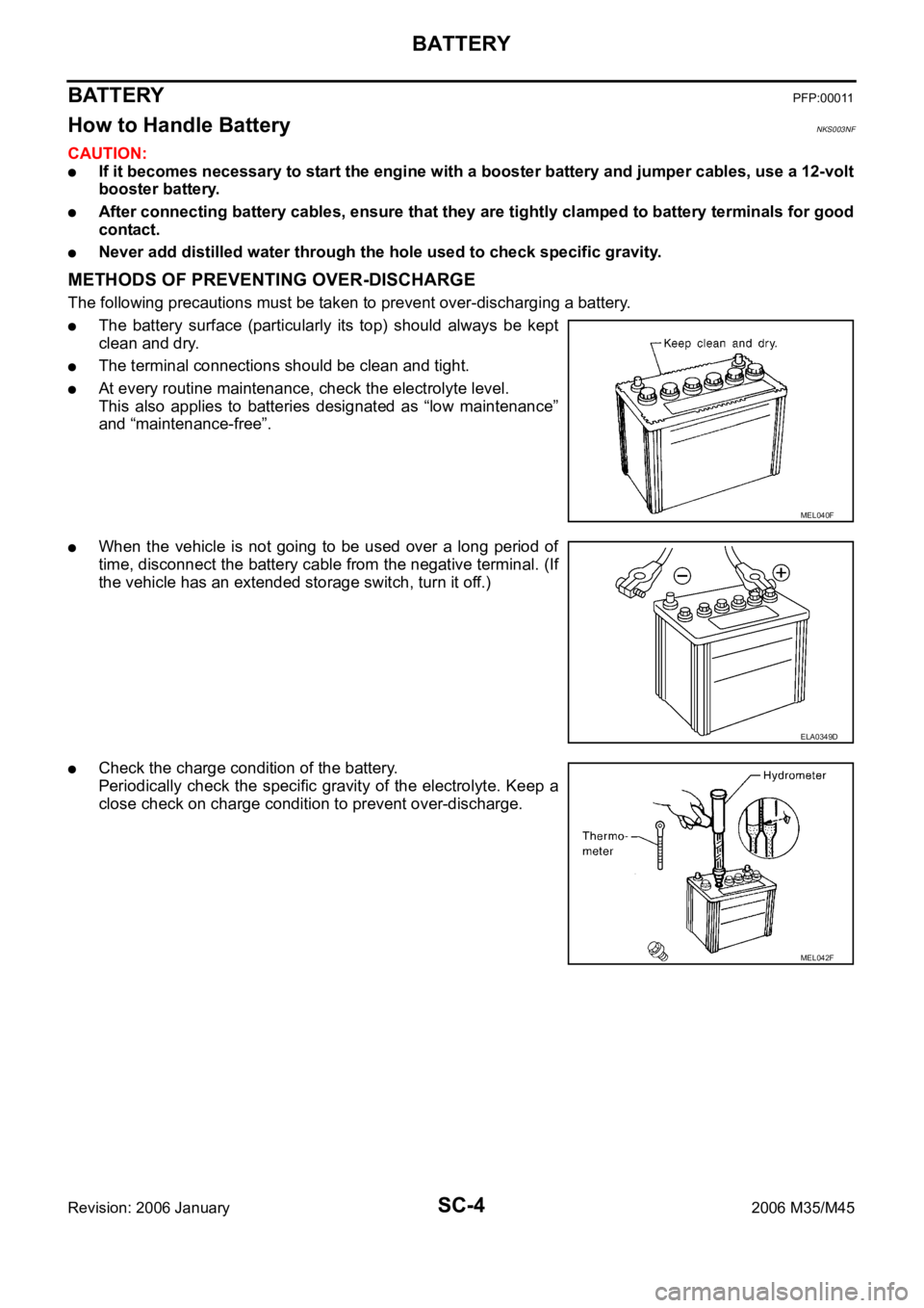
The following precautions must be taken to prevent over-discharging a battery.
The battery surface (particularly its top) should always be kept
clean and dry.
The terminal connections should be clean and tight.
At every routine maintenance, check the electrolyte level.
This also applies to batteries designated as “low maintenance”
and “maintenance-free”.
When the vehicle is not going to be used over a long period of
time, disconnect the battery cable from the negative terminal. (If
the vehicle has an extended storage switch, turn it off.)
Check the charge condition of the battery.
Periodically check the specific gravity of the electrolyte. Keep a
close check on charge condition to prevent over-discharge.
MEL040F
ELA0349D
MEL042F
Page 5142 of 5621
BATTERY
SC-5
C
D
E
F
G
H
I
J
L
MA
B
SC
Revision: 2006 January2006 M35/M45
CHECKING ELECTROLYTE LEVEL
WAR NING :
Never allow battery fluid to come in contact with skin, eyes, fabrics, or painted surfaces. After touch-
ing a battery, never touch or rub your eyes until you have thoroughly washed your hands. If acid con-
tacts eyes, skin or clothing, immediately flush with water for 15 minutes and seek medical attention.
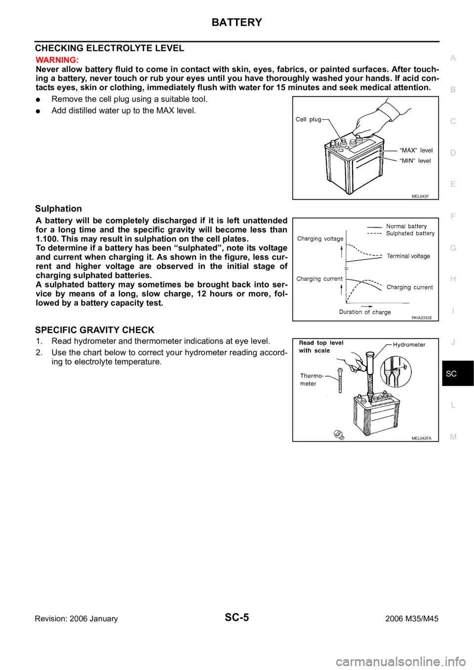
Remove the cell plug using a suitable tool.
Add distilled water up to the MAX level.
Sulphation
A battery will be completely discharged if it is left unattended
for a long time and the specific gravity will become less than
1.100. This may result in sulphation on the cell plates.
To determine if a battery has been “sulphated”, note its voltage
and current when charging it. As shown in the figure, less cur-
rent and higher voltage are observed in the initial stage of
charging sulphated batteries.
A sulphated battery may sometimes be brought back into ser-
vice by means of a long, slow charge, 12 hours or more, fol-
lowed by a battery capacity test.
SPECIFIC GRAVITY CHECK
1. Read hydrometer and thermometer indications at eye level.
2. Use the chart below to correct your hydrometer reading accord-
ing to electrolyte temperature.
MEL043F
PKIA2353E
MEL042FA
Page 5144 of 5621
BATTERY
SC-7
C
D
E
F
G
H
I
J
L
MA
B
SC
Revision: 2006 January2006 M35/M45
If, after charging, the specific gravity of any two cells varies more than 0.050, the battery should be
replaced.
Trouble Diagnosis with Battery/Starting/Charging System Tester (Battery)NKS003NG
CAUTION:
When working with batteries, always wear appropriate eye protection.
NOTE:
To ensure a complete and thorough diagnosis, the battery, starter and alternator test segments must be
done as a set from start to finish.
If battery surface charge is detected while testing, the tester will prompt you to turn on the headlamps to
remove the surface charge.
If necessary, the tester will prompt you to determine if the battery temperature is above or below 0 C (32
F). Choose the appropriate selection by pressing the up or down arrow button, then press “ENTER” to
make the selection.
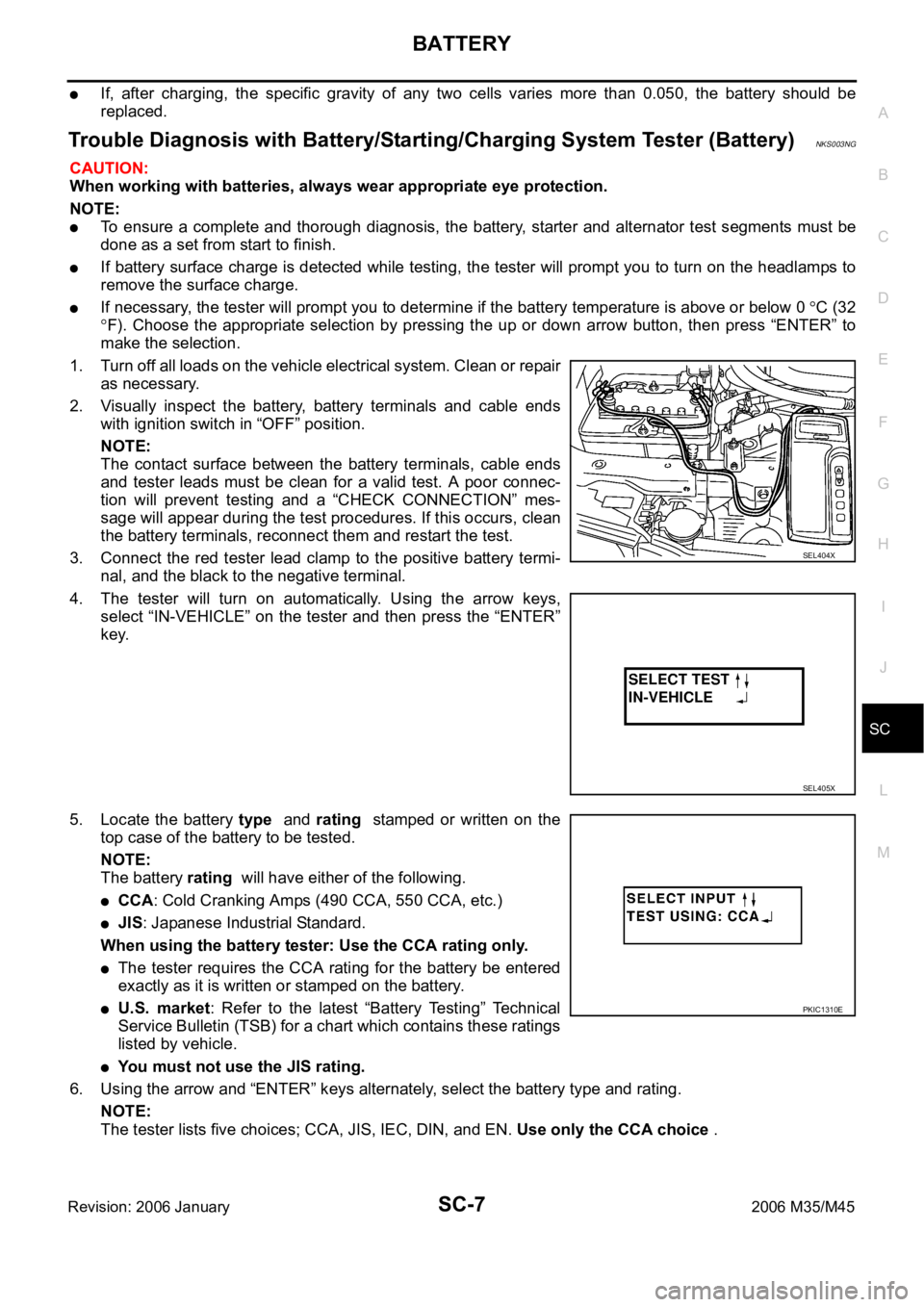
1. Turn off all loads on the vehicle electrical system. Clean or repair
as necessary.
2. Visually inspect the battery, battery terminals and cable ends
with ignition switch in “OFF” position.
NOTE:
The contact surface between the battery terminals, cable ends
and tester leads must be clean for a valid test. A poor connec-
tion will prevent testing and a “CHECK CONNECTION” mes-
sage will appear during the test procedures. If this occurs, clean
the battery terminals, reconnect them and restart the test.
3. Connect the red tester lead clamp to the positive battery termi-
nal, and the black to the negative terminal.
4. The tester will turn on automatically. Using the arrow keys,
select “IN-VEHICLE” on the tester and then press the “ENTER”
key.
5. Locate the battery type and rating stamped or written on the
top case of the battery to be tested.
NOTE:
The battery rating will have either of the following.
CCA: Cold Cranking Amps (490 CCA, 550 CCA, etc.)
JIS: Japanese Industrial Standard.
When using the battery tester: Use the CCA rating only.
The tester requires the CCA rating for the battery be entered
exactly as it is written or stamped on the battery.
U.S. market: Refer to the latest “Battery Testing” Technical
Service Bulletin (TSB) for a chart which contains these ratings
listed by vehicle.
You must not use the JIS rating.
6. Using the arrow and “ENTER” keys alternately, select the battery type and rating.
NOTE:
The tester lists five choices; CCA, JIS, IEC, DIN, and EN. Use only the CCA choice .
SEL404X
SEL405X
PKIC1310E
Page 5151 of 5621
SC-14
STARTING SYSTEM
Revision: 2006 January2006 M35/M45
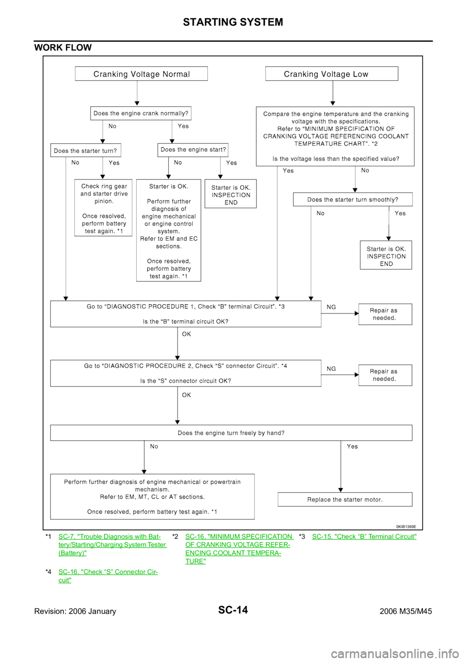
WORK FLOW
*1SC-7, "Trouble Diagnosis with Bat-
tery/Starting/Charging System Tester
(Battery)"
*2SC-16, "MINIMUM SPECIFICATION
OF CRANKING VOLTAGE REFER-
ENCING COOLANT TEMPERA-
TURE"
*3SC-15, "Check “B” Terminal Circuit"
*4SC-16, "Check “S” Connector Cir-
cuit"
SKIB1369E