INFINITI M35 2006 Factory Service Manual
Manufacturer: INFINITI, Model Year: 2006, Model line: M35, Model: INFINITI M35 2006Pages: 5621, PDF Size: 65.56 MB
Page 5541 of 5621

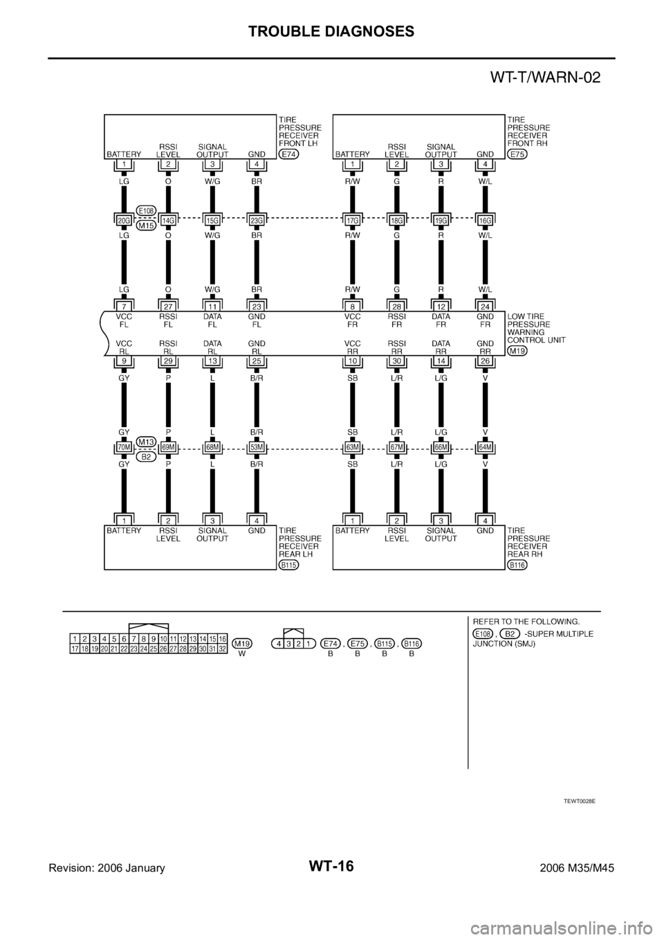
WT-16
TROUBLE DIAGNOSES
Revision: 2006 January2006 M35/M45
TEWT0028E
Page 5542 of 5621

TROUBLE DIAGNOSES
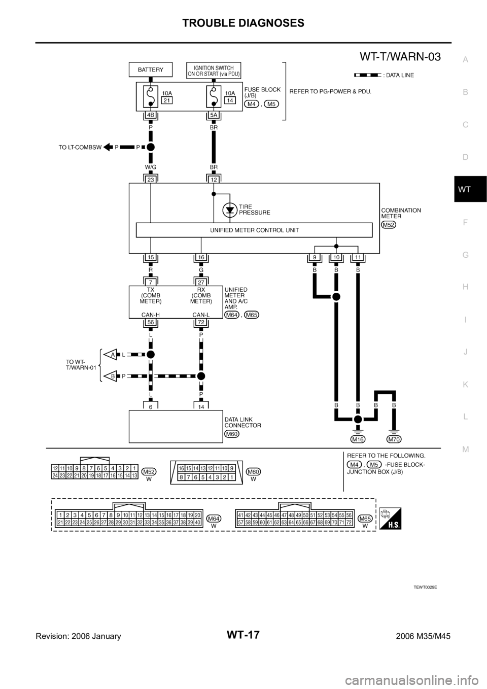
WT-17
C
D
F
G
H
I
J
K
L
MA
B
WT
Revision: 2006 January2006 M35/M45
TEWT0029E
Page 5543 of 5621

WT-18
TROUBLE DIAGNOSES
Revision: 2006 January2006 M35/M45
Control Unit Input/Output Signal StandardNES000JX
CAUTION:
When checked using a circuit tester for voltage measurement, connector terminals should not be
forcefully extended.
Terminal
Measuring point Measuring condition Standard
+
(wire color)–
2 (B/R)
GroundIgnition switch Ignition switch ON Battery voltage (12 V)
5 (W/R)Tire pressure warning check
connectorAlways Approx. 5 V
7 (LG)
Battery power supply
Ignition switch ONBattery voltage (12 V) 8 (R/W)
9 (GY)
10 (SB)
11 (W/G)
Signal Input Approx. 4.5 V 12 (R)
13 (L)
14 (L/G)
15 (L) Data line (CAN-H) — —
16 (P) Data line (CAN-L) — —
17 (B) Ground — 0 V
19 (G/R) HazardHazard lamp switch OFF Battery voltage (Approx. 12 V)
Hazard lamp switch ON 0 V
23 (BR)
Ground
—0 V
24 (W/L) — 0 V
25 (B/R) — 0 V
26 (V) — 0 V
27 (O)
Analog signal Ignition switch ON Approx. 0.7 V 28 (G)
29 (P)
30 (L/R)
Page 5544 of 5621

TROUBLE DIAGNOSES
WT-19
C
D
F
G
H
I
J
K
L
MA
B
WT
Revision: 2006 January2006 M35/M45
ID Registration ProcedureNES000JY
ID REGISTRATION WITH ACTIVATION TOOL
This procedure must be done after replacement of a tire pressure transmitter, low tire pressure warn-
ing control unit, or tire rotation.
CAUTION:
If CONSULT-II is used with no connection of CONSULT-II CONVERTER, malfunction might be detected
during self-diagnosis depending on control unit which performs CAN communication.
1. Turn ignition switch OFF.
2. Connect CONSULT-II and CONSULT-II CONVERTER to data link connector.
3. Turn ignition switch ON.
4. Touch “START (NISSAN BASED VHCL)” “AIR PRESSURE MONITOR”.
If “AIR PRESSURE MONITOR” is not displayed, print the “SELECT SYSTEM” screen. Then refer to
LAN-7, "
Precautions When Using CONSULT-II"
NOTE:
Just after starting engine, or turning ignition switch ON, it may not be displayed even if “START (NIS-
SAN BASED VHCL)” is touched. In this case, reconnect CONSULT-II and CONSULT-II CONVERTER.
5. Touch “WORK SUPPORT” on “SELECT DIAG MODE” screen.
6. Touch “ID REGIST” on “SELECT WORK ITEM”.
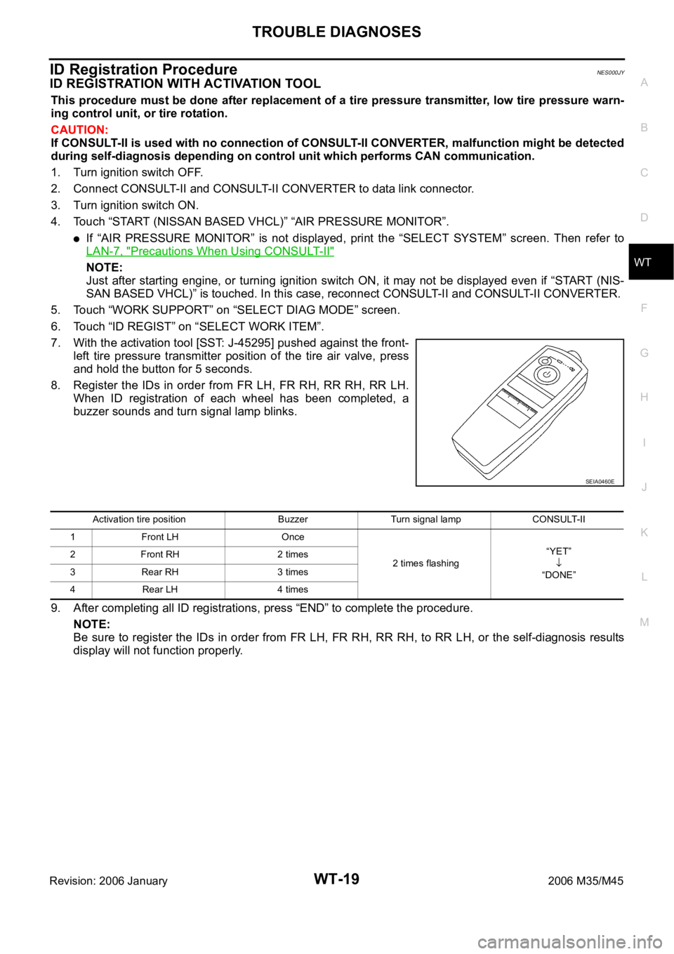
7. With the activation tool [SST: J-45295] pushed against the front-
left tire pressure transmitter position of the tire air valve, press
and hold the button for 5 seconds.
8. Register the IDs in order from FR LH, FR RH, RR RH, RR LH.
When ID registration of each wheel has been completed, a
buzzer sounds and turn signal lamp blinks.
9. After completing all ID registrations, press “END” to complete the procedure.
NOTE:
Be sure to register the IDs in order from FR LH, FR RH, RR RH, to RR LH, or the self-diagnosis results
display will not function properly.
SEIA0460E
Activation tire position Buzzer Turn signal lamp CONSULT-II
1 Front LH Once
2 times flashing“YET”
“DONE” 2 Front RH 2 times
3 Rear RH 3 times
4 Rear LH 4 times
Page 5545 of 5621

WT-20
TROUBLE DIAGNOSES
Revision: 2006 January2006 M35/M45
ID REGISTRATION WITHOUT ACTIVATION TOOL
This procedure must be done after replacement of a tire pressure transmitter, low tire pressure warn-
ing control unit, or tire rotation.
CAUTION:
If CONSULT-II is used with no connection of CONSULT-II CONVERTER, malfunction might be detected
during self-diagnosis depending on control unit which performs CAN communication.
1. Turn ignition switch OFF.
2. Connect CONSULT-II and CONSULT-II CONVERTER to data link connector.
3. Turn ignition switch ON.
4. Touch “START (NISSAN BASED VHCL)” “AIR PRESSURE MONITOR”.
If “AIR PRESSURE MONITOR” is not displayed, print the “SELECT SYSTEM” screen. Then refer to
LAN-7, "
Precautions When Using CONSULT-II" .
NOTE:
Just after starting engine, or turning ignition switch ON, it may not be displayed even if “START (NIS-
SAN BASED VHCL)” is touched. In this case, reconnect CONSULT-II and CONSULT-II CONVERTER.
5. Touch “WORK SUPPORT” on “SELECT DIAG MODE” screen.
6. Touch “ID REGIST” on “SELECT WORK ITEM”.
7. Adjust the tire pressure to the values shown in the table below for ID registration, and drive the vehicle at
40 km/h (25 MPH) or more for a few minutes.
8. After completing all ID registrations, press “END” to complete the procedure.
9. Inflate all tires to proper pressure. Refer to WT-41, "
SERVICE DATA AND SPECIFICATIONS (SDS)" .
Tire position
Tire pressure kPa (kg/cm2 , psi)
Front
Left 240 (2.4, 34)
Front
Right 220 (2.2, 31)
Rear
Right 200 (2.0, 29)
Rear
Left 180 (1.8, 26)
Activation tire position CONSULT-II
Front LH
“YET”
“DONE” Front RH
Rear RH
Rear LH
Page 5546 of 5621
![INFINITI M35 2006 Factory Service Manual TROUBLE DIAGNOSES
WT-21
C
D
F
G
H
I
J
K
L
MA
B
WT
Revision: 2006 January2006 M35/M45
Transmitter Wake Up OperationNES000JZ
WITH TRANSMITTER ACTIVATION TOOL
1. With the activation tool [SST: J-45295] p INFINITI M35 2006 Factory Service Manual TROUBLE DIAGNOSES
WT-21
C
D
F
G
H
I
J
K
L
MA
B
WT
Revision: 2006 January2006 M35/M45
Transmitter Wake Up OperationNES000JZ
WITH TRANSMITTER ACTIVATION TOOL
1. With the activation tool [SST: J-45295] p](/img/42/57023/w960_57023-5545.png)
TROUBLE DIAGNOSES
WT-21
C
D
F
G
H
I
J
K
L
MA
B
WT
Revision: 2006 January2006 M35/M45
Transmitter Wake Up OperationNES000JZ
WITH TRANSMITTER ACTIVATION TOOL
1. With the activation tool [SST: J-45295] pushed against the front-
left transmitter, press and hold the button for 5 seconds.
When ignition switch ON, as the low tire pressure warning
lamp blinks per the follow diagram, the respective transmitter
then must be woken up.
2. Register the ID of wheel that warning lamp flashes. When wake up of registered wheel has been com-
pleted, turn signal lamp flashes two times.
3. After completing wake up all transmitters, make sure low tire pressure warning lamp goes out.
CONSULT-II Function (AIR PRESSURE MONITOR)NES000K0
FUNCTION
CONSULT-II can display each diagnosis item using the diagnosis test modes shown following.
CONSULT-II SETTING PROCEDURE
Refer to GI-39, "CONSULT-II Start Procedure" .
SEIA0460E
SEIA0378E
Mode Function Reference
WORK SUPPORTThis mode enables a technician to adjust some devices faster and
more accurately by following the indications on CONSULT-II.WT-22, "
WORK SUP-
PORT MODE"
SELF-DIAG RESULTSReceives self-diagnosis results from low tire pressure warning con-
trol unit and indicates DTCs. WT-22, "SELF-DIAG
RESULT MODE"
DATA MONITORReceives input/output signals from low tire pressure warning control
unit and indicates and stores them to facilitate locating cause of mal-
functions.WT-23, "DATA MONITOR
MODE"
CAN DIAG SUPPORT MNTR Monitors transmitting/receiving status of CAN communication.WT-12, "CAN COMMUNI-
CATION"
ACTIVE TESTDiagnostic Test Mode in with CONSULT-II drives some actuators
apart from the low tire pressure warning control unit and also shifts
some parameters in a specified range.WT-23, "ACTIVE TEST
MODE"
ECU PART NUMBER Displays low tire pressure warning control unit part number. WT-24, "
LOW TIRE PRES-
SURE WARNING CON-
TROL UNIT PART
NUMBER"
Page 5547 of 5621

WT-22
TROUBLE DIAGNOSES
Revision: 2006 January2006 M35/M45
WORK SUPPORT MODE
Operation Procedure
1. Perform “CONSULT-II Start Procedure”. Refer to GI-39, "CONSULT-II Start Procedure" .
2. Perform the “ID Regist”. Refer to WT-19, "
ID Registration Procedure" .
SELF-DIAG RESULT MODE
Operation Procedure
1. Perform “CONSULT-II Start Procedure”. Refer to GI-39, "CONSULT-II Start Procedure" .
2. The self-diagnostic results are displayed. (Touch “PRINT” to print out the self-diagnostic results if neces-
sary.) Check low tire pressure warning lamp if “NO FAILURE” is displayed.
3. Perform the appropriate inspection from the display item list, and repair or replace the malfunctioning
component. Refer to WT-22, "
Display Item List" .
Display Item List
NOTE:
Before performing the self-diagnosis, be sure to register the ID, or else the actual malfunction location may be different from that dis-
played on CONSULT-II.DTC Diagnostic item Diagnostic item is detected when ꞏꞏꞏ Check items
C1700 FLAT_TIRE_FLFront-left tire pressure drops to * kPa (* kg/cm
2 , * psi) or less.
(Notice)
— C1701 FLAT_TIRE_FRFront-right tire pressure drops to * kPa (* kg/cm
2 , * psi) or less.
(Notice)
C1702 FLAT_TIRE_RRRear-right tire pressure drops to * kPa (* kg/cm
2 , * psi) or less.
(Notice)
C1703 FLAT_TIRE_RLRear-left tire pressure drops to * kPa (* kg/cm
2 , * psi) or less.
(Notice)
C1708 [NO_DATA]_FL Data from front-left transmitter cannot be received.
WT-30
C1709 [NO_DATA]_FR Data from front-right transmitter cannot be received.
C1710 [NO_DATA]_RR Data from rear-right transmitter cannot be received.
C1711 [NO_DATA]_RL Data from rear-left transmitter cannot be received.
C1716 [PRESSDATA_ERR]_FL Air pressure data from front-left transmitter is malfunctioning.
WT-32
C1717 [PRESSDATA_ERR]_FR Air pressure data from front-right transmitter is malfunctioning.
C1718 [PRESSDATA_ERR]_RR Air pressure data from rear-right transmitter is malfunctioning.
C1719 [PRESSDATA_ERR]_RL Air pressure data from rear-left transmitter is malfunctioning.
C1720 [CODE_ERROR]_FL Function code data from front-left transmitter is malfunctioning.
WT-32
C1721 [CODE_ERROR]_FR Function code data from front-right transmitter is malfunctioning.
C1722 [CODE_ERROR]_RR Function code data from rear-right transmitter is malfunctioning.
C1723 [CODE_ERROR]_RL Function code data from rear-left transmitter is malfunctioning.
C1724 [BATT_VOLT_LOW]_FL Battery voltage of front-left transmitter drops.
WT-33
C1725 [BATT_VOLT_LOW]_FR Battery voltage of front-right transmitter drops.
C1726 [BATT_VOLT_LOW]_RR Battery voltage of rear-right transmitter drops.
C1727 [BATT_VOLT_LOW]_RL Battery voltage of rear-left transmitter drops.
C1728 RECEIVER_ID_NO_REG ID registration of receiver is not completed.WT-33
C1729 VHCL_SPEED_SIG_ERR Vehicle speed signal is error.WT-34
C1750 [RECEIVER_ERR]_FL Data from front-left receiver cannot be received.
WT-31
C1751 [RECEIVER_ERR]_FR Data from front-right receiver cannot be received.
C1752 [RECEIVER_ERR]_RR Data from rear-right receiver cannot be received.
C1753 [RECEIVER_ERR]_RL Data from rear-left receiver cannot be received.
U1000 CAN COMM CIRCUITWhen a control unit (except for low tire pressure) is not transmit-
ting or receiving CAN communication signal 2 seconds or less. WT-34
Page 5548 of 5621

TROUBLE DIAGNOSES
WT-23
C
D
F
G
H
I
J
K
L
MA
B
WT
Revision: 2006 January2006 M35/M45
NOTICE:
186 kPa (1.86 kg/cm2 , 27 psi): Standard air pressure is for 230 kpa (2.3 kg/cm2 , 33 psi) vehicles.
How to Erase Self-Diagnostic Results
1. Perform applicable inspection of malfunctioning item and then repair or replace.
2. Start engine, and touch “START (NISSAN BASED VHCL)” “ AIR PRESSURE MONITOR” “SELF-DIAG
RESULTS” “ERASE” in this order to erase the diagnostic memory.
CAUTION:
If memory cannot be erased, repeat step 1, 2.
3. Perform self-diagnosis again, and make sure that DTC memory is erased.
DATA MONITOR MODE
Operation Procedure
1. Perform “CONSULT-II Start Procedure”. Refer to GI-39, "CONSULT-II Start Procedure" .
2. Touch “DATA MONITOR”.
3. Select from “SELECT MONITOR ITEM”, screen of data monitor is displayed.
NOTE:
When malfunction is detected, CONSULT-II performs REAL-TIME DIAGNOSIS. Also, any malfunction
detected while in this mode will be displayed in real time.
Display Item List
NOTE:
Before performing the self-diagnosis, be sure to register the ID, or else the actual malfunction location may be different from that dis-
played on CONSULT-II.
ACTIVE TEST MODE
Operation Procedure
1. Perform “CONSULT-II Start Procedure”. Refer to GI-39, "CONSULT-II Start Procedure" .
2. “ACTIVE TEST” is displayed.
Display Item List
NOTE:
Before performing the self-diagnosis, be sure to register the ID, or else the actual malfunction location may be different from that dis-
played on CONSULT-II.MONITOR CONDITION SPECIFICATION
VEHICLE SPEED SE Drive vehicle. Vehicle speed (km/h or MPH)
AIR PRESS FL
AIR PRESS FR
AIR PRESS RR
AIR PRESS RL
Drive vehicle for a few minutes.
Tire pressure (kPa or Psi) or
Ignition switch ON and activation tool
is transmitting activation signals.
ID REGST FL 1
ID REGST FR 1
ID REGST RR 1
ID REGST RL 1
Ignition switch ONRegistration ID: DONE
No registration ID: YET
WARNING LAMPLow tire pressure warning lamp on: ON
Low tire pressure warning lamp off: OFF
BUZZERBuzzer in combination meter on: ON
Buzzer in combination meter off: OFF
Test item Content
BUZZER This test is able to check to make sure that the buzzer sounds.
WARNING LAMP This test is able to check to make sure that the warning lamp turns on.
HAZARD LAMP This test is able to check to make sure that hazard lamp turns on.
Page 5549 of 5621

WT-24
TROUBLE DIAGNOSES
Revision: 2006 January2006 M35/M45
LOW TIRE PRESSURE WARNING CONTROL UNIT PART NUMBER
Operation Procedure
1. Perform “CONSULT-II Start Procedure”. Refer to GI-39, "CONSULT-II Start Procedure" .
2. The part number described on low tire pressure warning control unit sticker is displayed.
Diagnosis Procedure with Warning Lamp Function (Without CONSULT-II)NES000K6
DESCRIPTION
During driving, the low tire pressure warning system receives the signal transmitted from the transmitter
installed in each wheel, and gives alarms when the tire pressure becomes low. The control unit (low tire pres-
sure warning control unit) of this system has pressure judgement and trouble diagnosis functions.
FUNCTION
When the low tire pressure warning system detects low inflation pressure or another unusual symptom, the
warning lamps in the combination meter comes on. To start the self-diagnostic results mode, ground terminal
of the tire pressure warning check connector. The malfunction location is indicated by the warning lamp flash-
ing and the buzzer sounds. Regarding location of tire pressure warning check connector, refer to PG-63,
"HARNESS" .
LOW TIRE PRESSURE WARNING LAMP DIAGNOSTIC CHART
Diagnosis
ItemSymptom
(Ignition switch ON)Low tire pressure warning lamp Cause Action
Low tire pres-
sure warning
lampWarning light comes
on immediately and
turns off after 1 sec-
ond.All wheel transmit-
ters are “activated”
(working).None (system OK)
Warning light blinks
on for 2 seconds,
then turns off for 0.2
seconds-repeats.All wheel transmit-
ters are not acti-
vated.Activate all wheel tire pres-
sure transmitters. Refer to
WT-21, "
Transmitter Wake Up
Operation" .
Warning light blinks
1 time.Tire pressure trans-
mitter front LH is not
activated.Activate tire pressure trans-
mitter front LH. Refer to WT-
21, "Transmitter Wake Up
Operation" .
Warning light blinks
2 times.Tire pressure trans-
mitter front RH is not
activated.Activate tire pressure trans-
mitter front RH. Refer to WT-
21, "Transmitter Wake Up
Operation" .
Warning light blinks
3 times.Tire pressure trans-
mitter rear RH is not
activated.Activate tire pressure trans-
mitter rear RH. Refer to WT-
21, "Transmitter Wake Up
Operation" .
SEIA0592E
SEIA0593E
SEIA0594E
SEIA0595E
SEIA0596E
Page 5550 of 5621

TROUBLE DIAGNOSES
WT-25
C
D
F
G
H
I
J
K
L
MA
B
WT
Revision: 2006 January2006 M35/M45
NOTE:
If more than one wheel transmitter is NOT activated, the warning lamp blinking patterns for those wheels will combine. (Example: one
blink/OFF/three blinks = Tire pressure transmitter rear LH and rear RH are not activated.) Low tire pres-
sure warning
lampWarning light blinks
4 times.Tire pressure trans-
mitter rear LH is not
activated.Activate tire pressure trans-
mitter rear LH. Refer to WT-
21, "Transmitter Wake Up
Operation" .
Warning light comes
on and does not turn
off.Tire pressure is low.Check tire pressure with
CONSULT-II. Refer to WT-23,
"DATA MONITOR MODE" .
The fuse for combi-
nation meter from
battery is pulled out.Check the fuse for combina-
tion meter from battery. Install
or replace (if needed).
Low tire pressure
warning control unit
connector pulled outCheck low tire pressure warn-
ing control unit connector. Re-
connect if needed.
Low tire pressure or
low tire pressure
warning system mal-
function.
Perform CONSULT-II Self-
Diagnosis. Refer to WT-22,
"SELF-DIAG RESULT
MODE" .
–Perform ID Registration if
needed. Refer to WT-19,
"ID Registration Procedure"
.
Turn signal
lampTurn signal lamp
does not flash 2
times or buzzer does
not sound after
transmitter activa-
tion.—1. Tool J-45295
[SST]
2. Ignition OFF dur-
ing activation.
3. Tool J-45295
[SST] not posi-
tioned correctly.
4. Transmitters
already activated.1. Install new battery.
2. Make sure ignition is ON
during activation.
3. Position tool correctly dur-
ing activation.
4. None Diagnosis
ItemSymptom
(Ignition switch ON)Low tire pressure warning lamp Cause Action
SEIA0597E
SEIA0598E