INFINITI M35 2006 Factory Service Manual
Manufacturer: INFINITI, Model Year: 2006, Model line: M35, Model: INFINITI M35 2006Pages: 5621, PDF Size: 65.56 MB
Page 581 of 5621

ATC-134
IN-CABIN MICROFILTER
Revision: 2006 January2006 M35/M45
IN-CABIN MICROFILTERPFP:27277
Removal and InstallationNJS000HE
FUNCTION
Air inside passenger compartment is kept clean at either recircula-
tion or fresh mode by installing in-cabin microfilter into blower unit.
REPLACEMENT TIMING
Replace in-cabin microfilter.
Refer to MA-9, "
CHASSIS AND BODY MAINTENANCE" in Schedule 1 and MA-11, "CHASSIS AND BODY
MAINTENANCE" in Schedule 2.
When replacing filter, affix a caution label inside the glove box.
REPLACEMENT PROCEDURES
1. Remove glove box. Refer to IP-10, "INSTRUMENT PANEL ASSEMBLY" .
2. Remove filter cover, and then remove in-cabin microfilter.
3. Take out in-cabin microfilter from blower unit.
4. Replace with new one and reinstall on blower unit.
5. Reinstall glove box.
RJIA1331E
RJIA4116E
Page 582 of 5621

HEATER & COOLING UNIT ASSEMBLY
ATC-135
C
D
E
F
G
H
I
K
L
MA
B
AT C
Revision: 2006 January2006 M35/M45
HEATER & COOLING UNIT ASSEMBLYPFP:27110
Removal and InstallationNJS000HF
REMOVAL
1. Use a refrigerant collecting equipment (for HFC-134a) to discharge the refrigerant.
2. Drain coolant from cooling system. Refer to CO-11, "
Changing Engine Coolant" (VQ35DE) or CO-40,
"Changing Engine Coolant" (VK45DE).
3. Remove cowl top cover. Refer to EI-18, "
COWL TOP" .
4. Disconnect low-pressure flexible hose and high-pressure pipe 1
from evaporator.
a. Set a disconnector [high-pressure side (SST: 9253089908), low-
pressure side (SST: 9253089916)] on A/C piping.
b. Slide a disconnector toward vehicle front until it clicks.
c. Slide A/C piping toward vehicle front and disconnect it.
CAUTION:
Cap or wrap the joint of the pipe with suitable material such
as vinyl tape to avoid the entry of air.
5. Remove electric throttle control actuator. Refer to EM-19,
"INTAKE MANIFOLD COLLECTOR" (VQ35DE) or EM-179,
"INTAKE MANIFOLD" (VK45DE).
6. Disconnect two heater hoses from heater core.
7. Remove instrument panel & pad. Refer to IP-10, "
INSTRUMENT PANEL ASSEMBLY" .
8. Remove blower unit. Refer to ATC-130, "
BLOWER UNIT" .
9. Remove clips of vehicle harness from steering member.
10. Remove mounting nuts and bolts, and then remove instrument stays.
RJIA4117E
RJIA4118E
RJIA4119E
Page 583 of 5621

ATC-136
HEATER & COOLING UNIT ASSEMBLY
Revision: 2006 January2006 M35/M45
11. Disconnect drain hose.
12. Remove mounting bolts from heater & cooling unit.
13. Remove side defroster nozzles.
14. Remove steering column mounting bolts and nut.
15. Remove steering member mounting bolts.
16. Remove steering member, and then remove heater & cooling unit.
INSTALLATION
Installation is basically the reverse order of removal.
RJIA4180E
RJIA4120E
RJIA4121E
Page 584 of 5621

HEATER & COOLING UNIT ASSEMBLY
ATC-137
C
D
E
F
G
H
I
K
L
MA
B
AT C
Revision: 2006 January2006 M35/M45
CAUTION:
Replace O-rings of A/C piping with new ones, and then apply compressor oil to it when installing
it.
Female-side piping connection is thin and easy to deform. Slowly insert the male-side piping
straight in axial direction.
Insert piping securely until a click is heard.
After piping connection is completed, pull male-side piping by hand to make sure that connection
does not come loose.
When recharging refrigerant, check for leaks.
NOTE:
When filling radiator with coolant, refer to CO-11, "Changing Engine Coolant" (VQ35DE) or CO-40,
"Changing Engine Coolant" (VK45DE).
Recharge the refrigerant.
Heater & cooling unit assembly mounting bolt
: 6.9 Nꞏm (0.7 kg-m, 61 in-lb)
Instrument stay mounting nut and bolt
: 12 Nꞏm (1.25 kg-m, 9 ft-lb)
Page 585 of 5621

4. Foot duct (left) 5. Ventilator")
ATC-138
HEATER & COOLING UNIT ASSEMBLY
Revision: 2006 January2006 M35/M45
Disassembly and AssemblyNJS000HG
1. Aspirator 2. Aspirator hose 3. Front heater duct (left)
4. Foot duct (left) 5. Ventilator door (left) 6. Ventilator door (right)
7. Foot duct (right) 8. Main link sub (right) 9. Ventilator door lever (right)
10. Ventilator door link (right) 11. Main link (right) 12. Mode door motor (passenger side)
13. Max. cool door link (right) 14. Air mix door motor (passenger side) 15. Intake sensor
16. Intake sensor bracket 17. Low-pressure pipe 1 18. High-pressure pipe 2
19. Expansion valve 20. Cooler pipe grommet 21. Insulator
22. Evaporator cover adapter 23. Air mix door (Slide door) 24. Clip
25. Heater & cooling unit case (left) 26. Heater pipe grommet 27. Heater core
28. Upper ventilator door motor 29. Air mix door motor (driver side) 30. Mode door motor (driver side)
31. Main link (left) 32. Main link sub (left) 33. Ventilator door lever (left)
34. Center case 35. Max. cool door lever (right) 36. Evaporator cover
RJIA4122E
Page 586 of 5621
 39. Upper ventilator door
40. Heater pipe c")
HEATER & COOLING UNIT ASSEMBLY
ATC-139
C
D
E
F
G
H
I
K
L
MA
B
AT C
Revision: 2006 January2006 M35/M45
37. Evaporator 38. Heater & cooling unit case (right) 39. Upper ventilator door
40. Heater pipe cover 41. Upper ventilator door rod 42. Upper ventilator door lever
43. Defroster door link 44. Ventilator door link (left) 45. Max. cool door lever (left)
46. Max. cool door (left) 47. Max. cool door (right) 48. Defroster door (right)
49. Defroster door (left) 50. Max. cool door link (left) 51. Defroster door lever
Page 587 of 5621
ATC-140
MODE DOOR MOTOR
Revision: 2006 January2006 M35/M45
MODE DOOR MOTORPFP:27731
Removal and InstallationNJS000HH
REMOVAL
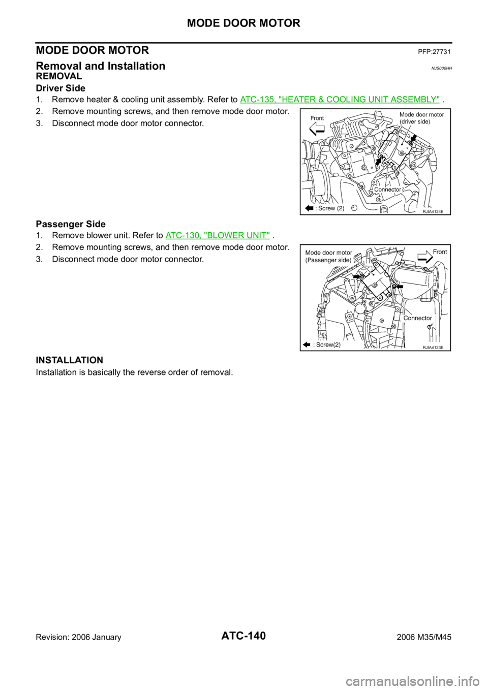
Driver Side
1. Remove heater & cooling unit assembly. Refer to ATC-135, "HEATER & COOLING UNIT ASSEMBLY" .
2. Remove mounting screws, and then remove mode door motor.
3. Disconnect mode door motor connector.
Passenger Side
1. Remove blower unit. Refer to ATC-130, "BLOWER UNIT" .
2. Remove mounting screws, and then remove mode door motor.
3. Disconnect mode door motor connector.
INSTALLATION
Installation is basically the reverse order of removal.
RJIA4124E
RJIA4123E
Page 588 of 5621

AIR MIX DOOR MOTOR
ATC-141
C
D
E
F
G
H
I
K
L
MA
B
AT C
Revision: 2006 January2006 M35/M45
AIR MIX DOOR MOTOR PFP:27732
Removal and InstallationNJS000HI
REMOVAL
Driver Side
1. Set the temperature (driver side) at 18C (60F), and then disconnect the battery cable from the negative
terminal.
2. Remove heater & cooling unit assembly. Refer to ATC-135, "
HEATER & COOLING UNIT ASSEMBLY" .
3. Remove mounting screws, and then remove air mix door motor.
4. Disconnect air mix door motor connector.
Passenger Side
1. Set the temperature (passenger side) at 18C (60F), and then disconnect the battery cable from the neg-
ative terminal.
2. Remove blower unit. Refer to ATC-130, "
BLOWER UNIT" .
3. Remove mounting screws, and then remove air mix door motor.
4. Disconnect air mix door motor connector.
INSTALLATION
Installation is basically the reverse order of removal.
RJIA4126E
RJIA4125E
Page 589 of 5621

ATC-142
UPPER VENTILATOR DOOR MOTOR
Revision: 2006 January2006 M35/M45
UPPER VENTILATOR DOOR MOTORPFP:27731
Removal and InstallationNJS000HJ
REMOVAL
1. Remove heater & cooling unit assembly. Refer to ATC-135, "HEATER & COOLING UNIT ASSEMBLY" .
2. Remove mounting screws.
3. Disconnect upper ventilator door motor connector.
4. Disconnect upper ventilator door rod, and then remove upper
ventilator door motor.
INSTALLATION
Installation is basically the reverse order of removal.
RJIA4127E
Page 590 of 5621

HEATER CORE
ATC-143
C
D
E
F
G
H
I
K
L
MA
B
AT C
Revision: 2006 January2006 M35/M45
HEATER COREPFP:27140
Removal and InstallationNJS000HK
REMOVAL
1. Remove heater & cooling unit assembly. Refer to ATC-135, "HEATER & COOLING UNIT ASSEMBLY" .
2. Remove mounting screws, and then remove heater pipe cover.
3. Remove mounting screws, and then remove foot duct (left).
4. Slide heater core (shown in the figure) to leftward.
INSTALLATION
Installation is basically the reverse order of removal.
RJIA4128E