INFINITI M35 2006 Factory Service Manual
Manufacturer: INFINITI, Model Year: 2006, Model line: M35, Model: INFINITI M35 2006Pages: 5621, PDF Size: 65.56 MB
Page 921 of 5621
![INFINITI M35 2006 Factory Service Manual AV-300
[WITH MOBILE ENTERTAINMENT SYSTEM]
REMOVAL AND INSTALLATION
Revision: 2006 January2006 M35/M45 INFINITI M35 2006 Factory Service Manual AV-300
[WITH MOBILE ENTERTAINMENT SYSTEM]
REMOVAL AND INSTALLATION
Revision: 2006 January2006 M35/M45](/img/42/57023/w960_57023-920.png)
AV-300
[WITH MOBILE ENTERTAINMENT SYSTEM]
REMOVAL AND INSTALLATION
Revision: 2006 January2006 M35/M45
Page 922 of 5621

BCS-1
BODY CONTROL SYSTEM
K ELECTRICAL
CONTENTS
C
D
E
F
G
H
I
J
L
M
SECTION BCS
A
B
BCS
Revision: 2006 January2006 M35/M45
BODY CONTROL SYSTEM
PRECAUTIONS .......................................................... 2
Precautions for Supplemental Restraint System
(SRS) “AIR BAG” and “SEAT BELT PRE-TEN-
SIONER” .................................................................. 2
BCM (BODY CONTROL MODULE) ........................... 3
System Description .................................................. 3
BCM FUNCTION ................................................... 3
COMBINATION SWITCH READING FUNCTION ..... 3
CAN COMMUNICATION CONTROL .................... 6
BCM STATUS CONTROL ..................................... 7
SYSTEMS CONTROLLED BY BCM DIRECTLY ..... 8
SYSTEMS CONTROLLED BY BCM AND IPDM
E/R ........................................................................ 8
SYSTEMS CONTROLLED BY BCM AND COM-
BINATION METER ................................................ 8
SYSTEMS CONTROLLED BY BCM AND INTEL-
LIGENT KEY UNIT ................................................ 8SYSTEMS CONTROLLED BY BCM, COMBINA-
TION METER AND IPDM E/R ............................... 8
MAJOR COMPONENTS AND CONTROL SYS-
TEM ....................................................................... 9
CAN Communication Unit ....................................... 10
Schematic ............................................................... 11
CONSULT-II Function (BCM) ................................. 13
CONSULT-II BASIC OPERATION ....................... 13
ITEMS OF EACH PART ...................................... 14
WORK SUPPORT ............................................... 15
CAN DIAG SUPPORT MNTR ............................. 15
CAN Communication Inspection Using CONSULT-
II (Self-Diagnosis) ................................................... 15
Check BCM Power Supply and Ground Circuit ...... 16
Removal and Installation of BCM ........................... 17
REMOVAL ........................................................
... 17
INSTALLATION ................................................... 17
Page 923 of 5621

BCS-2
PRECAUTIONS
Revision: 2006 January2006 M35/M45
PRECAUTIONSPFP:00001
Precautions for Supplemental Restraint System (SRS) “AIR BAG” and “SEAT
BELT PRE-TENSIONER”
NKS003XG
The Supplemental Restraint System such as “AIR BAG” and “SEAT BELT PRE-TENSIONER”, used along
with a front seat belt, helps to reduce the risk or severity of injury to the driver and front passenger for certain
types of collision. This system includes seat belt switch inputs and dual stage front air bag modules. The SRS
system uses the seat belt switches to determine the front air bag deployment, and may only deploy one front
air bag, depending on the severity of a collision and whether the front occupants are belted or unbelted.
Information necessary to service the system safely is included in the SRS and SB section of this Service Man-
ual.
WAR NING :
To avoid rendering the SRS inoperative, which could increase the risk of personal injury or death
in the event of a collision which would result in air bag inflation, all maintenance must be per-
formed by an authorized NISSAN/INFINITI dealer.
Improper maintenance, including incorrect removal and installation of the SRS, can lead to per-
sonal injury caused by unintentional activation of the system. For removal of Spiral Cable and Air
Bag Module, see the SRS section.
Do not use electrical test equipment on any circuit related to the SRS unless instructed to in this
Service Manual. SRS wiring harnesses can be identified by yellow and/or orange harnesses or
harness connectors.
Page 924 of 5621
BCM (BODY CONTROL MODULE)
BCS-3
C
D
E
F
G
H
I
J
L
MA
B
BCS
Revision: 2006 January2006 M35/M45
BCM (BODY CONTROL MODULE)PFP:284B2
System DescriptionNKS003XH
BCM (Body Control Module) controls the operation of various electrical units installed on the vehicle.
BCM FUNCTION
BCM has combination switch reading function for reading the operation of combination switches (light, wiper,
washer, turn signal) in addition to a function for controlling the operation of various electrical components. Also
it has an interface function allowing it to receive signals from the combination meter, and send signals to ECM
using CAN communication.
COMBINATION SWITCH READING FUNCTION
Description
BCM reads combination switch (lighting switch, wiper switch) status, and controls various electrical com-
ponent according to the result.
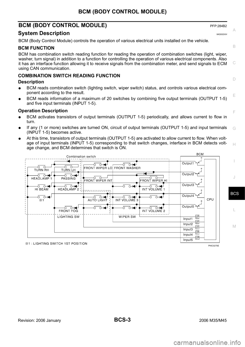
BCM reads information of a maximum of 20 switches by combining five output terminals (OUTPUT 1-5)
and five input terminals (INPUT 1-5).
Operation Description
BCM activates transistors of output terminals (OUTPUT 1-5) periodically, and allows current to flow in
turn.
If any (1 or more) switches are turned ON, circuit of output terminals (OUTPUT 1-5) and input terminals
(INPUT 1-5) becomes active.
At this time, transistors of output terminals (OUTPUT 1-5) are activated to allow current to flow. When volt-
age of input terminals (INPUT 1-5) corresponding to that switch changes, interface in BCM detects volt-
age change, and BCM determines that switch is ON.
PKIC0270E
Page 925 of 5621
BCS-4
BCM (BODY CONTROL MODULE)
Revision: 2006 January2006 M35/M45
Operation Table of BCM and Combination Switches
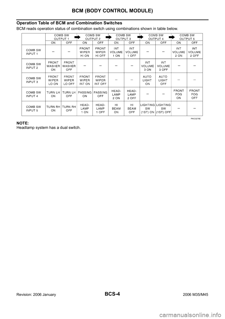
BCM reads operation status of combination switch using combinations shown in table below.
NOTE:
Headlamp system has a dual switch.
PKIC0276E
Page 926 of 5621
BCM (BODY CONTROL MODULE)
BCS-5
C
D
E
F
G
H
I
J
L
MA
B
BCS
Revision: 2006 January2006 M35/M45
Sample Operation:
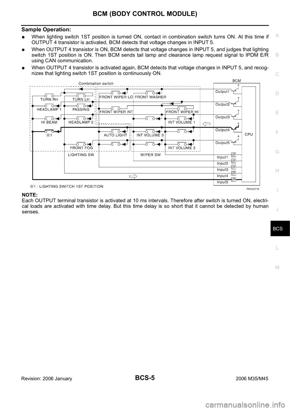
When lighting switch 1ST position is turned ON, contact in combination switch turns ON. At this time if
OUTPUT 4 transistor is activated, BCM detects that voltage changes in INPUT 5.
When OUTPUT 4 transistor is ON, BCM detects that voltage changes in INPUT 5, and judges that lighting
switch 1ST position is ON. Then BCM sends tail lamp and clearance lamp request signal to IPDM E/R
using CAN communication.
When OUTPUT 4 transistor is activated again, BCM detects that voltage changes in INPUT 5, and recog-
nizes that lighting switch 1ST position is continuously ON.
NOTE:
Each OUTPUT terminal transistor is activated at 10 ms intervals. Therefore after switch is turned ON, electri-
cal loads are activated with time delay. But this time delay is so short that it cannot be detected by human
senses.
PKIC0271E
Page 927 of 5621
BCS-6
BCM (BODY CONTROL MODULE)
Revision: 2006 January2006 M35/M45
Operation Mode
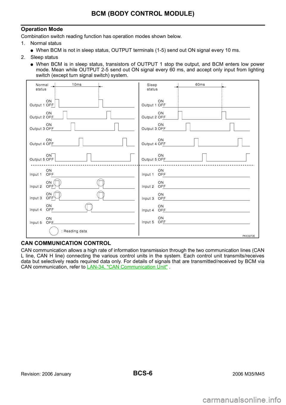
Combination switch reading function has operation modes shown below.
1. Normal status
When BCM is not in sleep status, OUTPUT terminals (1-5) send out ON signal every 10 ms.
2. Sleep status
When BCM is in sleep status, transistors of OUTPUT 1 stop the output, and BCM enters low power
mode. Mean while OUTPUT 2-5 send out ON signal every 60 ms, and accept only input from lighting
switch (except turn signal switch) system.
CAN COMMUNICATION CONTROL
CAN communication allows a high rate of information transmission through the two communication lines (CAN
L line, CAN H line) connecting the various control units in the system. Each control unit transmits/receives
data but selectively reads required data only. For details of signals that are transmitted/received by BCM via
CAN communication, refer to LAN-34, "
CAN Communication Unit" .
PKIC0272E
Page 928 of 5621

BCM (BODY CONTROL MODULE)
BCS-7
C
D
E
F
G
H
I
J
L
MA
B
BCS
Revision: 2006 January2006 M35/M45
BCM STATUS CONTROL
BCM changes its status depending on the operation status in order to save power consumption.
1. CAN communication status
With ignition switch ON, CAN communicates with other control units normally.
Control by BCM is being operated properly.
When ignition switch is OFF, switching to sleep mode is possible.
Even when ignition switch is OFF, if CAN communication with IPDM E/R and combination meter is
active, CAN communication status is active.
2. Sleep transient status
This status shuts down CAN communication when ignition switch is turned OFF.
It transmits sleep request signal to IPDM E/R and combination meter.
Two seconds after CAN communication of all control units stops, sleep transient status switches to CAN
communication inactive status.
3. CAN communication inactive status
With ignition switch OFF, CAN communication is not active.
With ignition switch OFF, control performed only by BCM is active.
Three seconds after CAN communication of all control units stops, CAN communication inactive status
switches to sleep status.
4. Sleep status
BCM is activated with low power mode.
CAN communication is not active.
When CAN communication operation is detected, it switches to CAN communication status.
When a state of the following switches changes, it switches to CAN communication status.
–Key switch (ACC, ON)
–Key slot
–Intelligent Key (lock/unlock signal)
–Hazard switch
–Door lock/unlock switch
–Front door switch (driver side, passenger side)
–Rear door switch (LH, RH)
–Trunk lid opener switch
–Combination switch (passing, lighting switch 1ST position, front fog lamp)
–Key cylinder switch
When control performed only by BCM is required by switch, it shifts to CAN communication inactive
mode.
Status of combination switch reading function is changed to low power consumption mode.
Page 929 of 5621
BCS-8
BCM (BODY CONTROL MODULE)
Revision: 2006 January2006 M35/M45
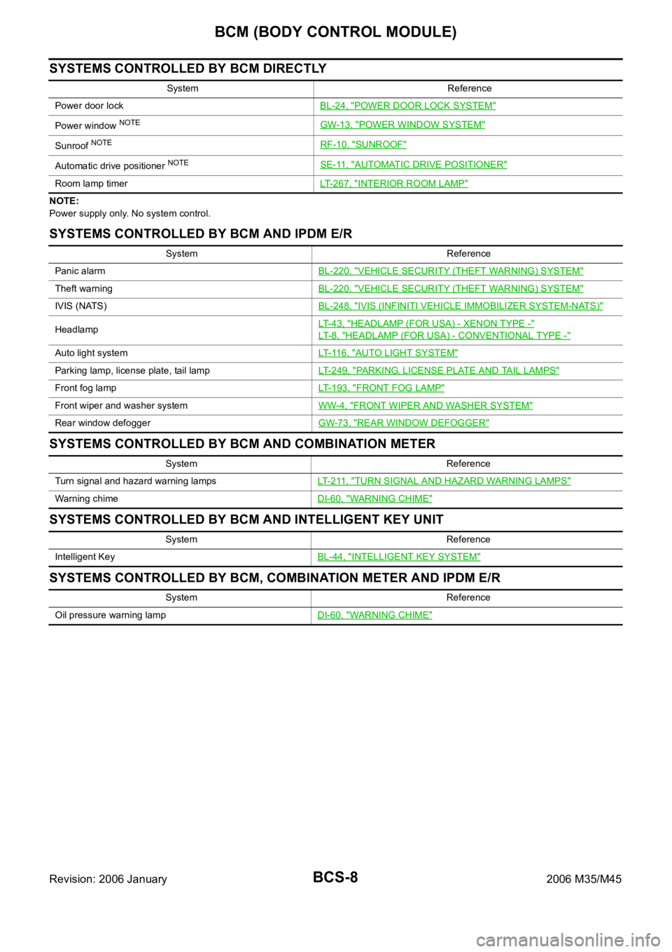
SYSTEMS CONTROLLED BY BCM DIRECTLY
NOTE:
Power supply only. No system control.
SYSTEMS CONTROLLED BY BCM AND IPDM E/R
SYSTEMS CONTROLLED BY BCM AND COMBINATION METER
SYSTEMS CONTROLLED BY BCM AND INTELLIGENT KEY UNIT
SYSTEMS CONTROLLED BY BCM, COMBINATION METER AND IPDM E/R
System Reference
Power door lockBL-24, "
POWER DOOR LOCK SYSTEM"
Power window NOTEGW-13, "POWER WINDOW SYSTEM"
Sunroof NOTERF-10, "SUNROOF"
Automatic drive positioner NOTESE-11, "AUTOMATIC DRIVE POSITIONER"
Room lamp timerLT-267, "INTERIOR ROOM LAMP"
System Reference
Panic alarmBL-220, "
VEHICLE SECURITY (THEFT WARNING) SYSTEM"
Theft warningBL-220, "VEHICLE SECURITY (THEFT WARNING) SYSTEM"
IVIS (NATS)BL-248, "IVIS (INFINITI VEHICLE IMMOBILIZER SYSTEM-NATS)"
HeadlampLT- 4 3 , "HEADLAMP (FOR USA) - XENON TYPE -"
LT- 8 , "HEADLAMP (FOR USA) - CONVENTIONAL TYPE -"
Auto light systemLT- 11 6 , "AUTO LIGHT SYSTEM"
Parking lamp, license plate, tail lampLT-249, "PARKING, LICENSE PLATE AND TAIL LAMPS"
Front fog lampLT-193, "FRONT FOG LAMP"
Front wiper and washer systemWW-4, "FRONT WIPER AND WASHER SYSTEM"
Rear window defoggerGW-73, "REAR WINDOW DEFOGGER"
System Reference
Turn signal and hazard warning lampsLT- 2 11 , "
TURN SIGNAL AND HAZARD WARNING LAMPS"
Warning chimeDI-60, "WARNING CHIME"
System Reference
Intelligent KeyBL-44, "
INTELLIGENT KEY SYSTEM"
System Reference
Oil pressure warning lampDI-60, "
WARNING CHIME"
Page 930 of 5621

BCM (BODY CONTROL MODULE)
BCS-9
C
D
E
F
G
H
I
J
L
MA
B
BCS
Revision: 2006 January2006 M35/M45
MAJOR COMPONENTS AND CONTROL SYSTEM
NOTE:
*1: Functions only when the Intelligent Key is inserted in key slot.
*2: With navigation system
*3: Without navigation systemSystem Input Output
Intelligent Key system Intelligent Key unit
All door locking actuator
Trunk lid opener actuator
Turn signal lamp (LH, RH)
Combination meter
Power door lock system
Power window main switch (door lock and unlock switch)
Power window sub switch (passenger side)
(door lock and unlock switch)All-door locking actuator
Power supply (IGN) to power win-
dow, sunroofIgnition power supply Power window and sunroof system
Power supply (BAT) to power
window, sunroof and power seatBattery power supplyPower window, sunroof system and
power seat
Panic alarm
Key slot
Intelligent KeyIPDM E/R
Theft warning system
All-door switch
Hood switch
Intelligent Key
Power window main switch (door lock and unlock switch)
IPDM E/R
Security indicator lamp
Auto light system
Optical sensor
Combination switchIPDM E/R
Battery saver control
Ignition switch
Combination switchIPDM E/R
Headlamp
Tail lamp
Front fog lampCombination switch IPDM E/R
Turn signal lamp Combination switch
Turn signal lamp
Combination meter
Hazard lamp Hazard switch
Turn signal lamp
Combination meter
Room lamp timer
Key switch
Power window main switch (door lock and unlock switch)
Front door switch driver side
All-door switchInterior room lamp
Key warning chime*
1Key switch
Front door switch driver sideCombination meter (warning buzzer)
Light warning chime
Combination switch
Front door switch driver sideCombination meter (warning buzzer)
Seat belt warning chime
Combination meter [Seat belt buckle (driver side) switch]
Ignition switchCombination meter (warning buzzer)
Vehicle-speed-sensing intermit-
tent wiper
Combination switch
Unified meter and A/C amp.IPDM E/R
Rear window defogger
Multifunction switch
NAVI control unit*2
AV control unit*3
IPDM E/R