IDX INFINITI QX4 2001 Factory Service Manual
[x] Cancel search | Manufacturer: INFINITI, Model Year: 2001, Model line: QX4, Model: INFINITI QX4 2001Pages: 2395, PDF Size: 43.2 MB
Page 1984 of 2395

SLC031B
2. Install water pump.
IDo not allow cylinder block to nip O-rings when installing
water pump.
SLC944A
3. Before installing, remove all traces of liquid gasket from mat-
ing surface of water pump cover and chain tensioner cover
using a scraper.
Also remove traces of liquid gasket from mating surface of
front cover.
SLC945AA
4. Apply a continuous bead of liquid gasket to mating surface of
chain tensioner cover and water pump cover.
SLC156B
5. Return the crankshaft pulley to its original position by turning
it 20É forward.
SLC961A
6. Install timing chain tensioner, then remove the stopper pin.
IWhen installing the timing chain tensioner, engine oil
should be applied to the oil hole and tensioner.
IAfter starting engine, let idle for three minutes, then rev
engine up to 3,000 rpm under no load to purge air from the
high-pressure chamber of the chain tensioners. The
engine may produce a rattling noise. This indicates that
air still remains in the chamber and is not a matter of
concern.
7. Reinstall any parts removed in reverse order of removal.
GI
MA
EM
EC
FE
AT
TF
PD
AX
SU
BR
ST
RS
BT
HA
SC
EL
IDX
ENGINE COOLING SYSTEM
Water Pump (Cont'd)
LC-15
Page 1986 of 2395

3. Then check if valve closes at 5ÉC (9ÉF) below valve opening
temperature.
Water Control Valve
REMOVAL AND INSTALLATIONNBLC0032
SLC330B
1. Water outlet housing
2. Water control valve
3. Water outlet4. Water hose
5. Cylinder block water outlet
6. Thermal transmitter7. Engine coolant temperature sen-
sor
1. Release fuel pressure.
Refer to EC-39, ªFuel Pressure Releaseº.
2. Remove under cover.
3. Remove suspension member stay.
4. Drain coolant from radiator.
5. Remove engine cover.
6. Remove air duct with air cleaner assembly.
7. Disconnect wires, hoses, harness and so on.
8. Remove upper intake manifold corrector.
9. Remove intake manifold corrector support bolts.
10. Remove lower intake manifold corrector.
11. Disconnect injector harness connectors.
12. Remove injector tube.
13. Remove intake manifold.
14. Remove water outlet housing and water control valve.
GI
MA
EM
EC
FE
AT
TF
PD
AX
SU
BR
ST
RS
BT
HA
SC
EL
IDX
ENGINE COOLING SYSTEM
Thermostat (Cont'd)
LC-17
Page 1988 of 2395

Radiator
REMOVAL AND INSTALLATION=NBLC00231. Remove under cover.
2. Remove suspension member stay.
3. Drain coolant from radiator.
4. Disconnect radiator upper and lower hoses.
5. Remove upper and lower radiator shroud.
6. Remove A/T oil cooler hoses.
7. Disconnect reservoir tank hose.
8. Remove radiator mounting bracket.
9. Remove radiator.
10. After repairing or replacing radiator, install any part removed in reverse order of removal.
When filling radiator with coolant, refer to MA-14, ªChanging Engine Coolantº.
SLC331B
GI
MA
EM
EC
FE
AT
TF
PD
AX
SU
BR
ST
RS
BT
HA
SC
EL
IDX
ENGINE COOLING SYSTEM
Radiator
LC-19
Page 1990 of 2395

Radiator (Aluminum type)
PREPARATIONNBLC0025
SLC882AB
SLC655CB
1. Attach the spacer to the tip of the radiator plate pliers A. Spacer
specification: 1.5 mm (0.059 in) thick x 18 mm (0.71 in) wide
x 8.5 mm (0.335 in) long.
2. Make sure that when radiator plate pliers A are closed dimen-
sion H¢¢is approx. 7.6 mm (0.299 in).
3. Adjust dimension H¢¢with the spacer, if necessary.
SLC903-A
DISASSEMBLYNBLC00261. Remove tank with Tool.
SLC893
IGrip the crimped edge and bend it upwards so that Tool slips
off.
Do not bend excessively.
GI
MA
EM
EC
FE
AT
TF
PD
AX
SU
BR
ST
RS
BT
HA
SC
EL
IDX
ENGINE COOLING SYSTEM
Radiator (Aluminum type)
LC-21
Page 1992 of 2395

SLC904-A
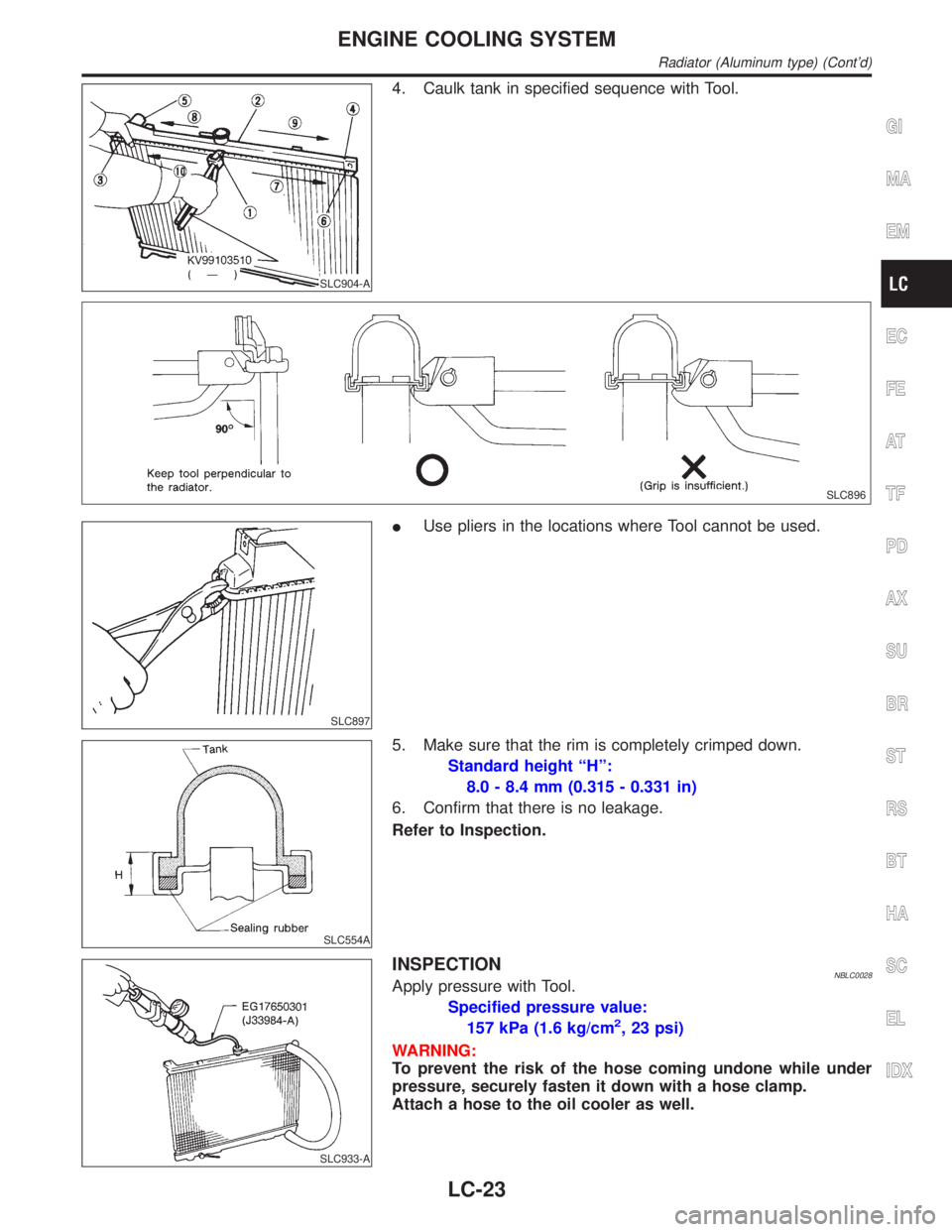
4. Caulk tank in specified sequence with Tool.
SLC896
SLC897
IUse pliers in the locations where Tool cannot be used.
SLC554A
5. Make sure that the rim is completely crimped down.
Standard height ªHº:
8.0 - 8.4 mm (0.315 - 0.331 in)
6. Confirm that there is no leakage.
Refer to Inspection.
SLC933-A
INSPECTIONNBLC0028Apply pressure with Tool.
Specified pressure value:
157 kPa (1.6 kg/cm
2, 23 psi)
WARNING:
To prevent the risk of the hose coming undone while under
pressure, securely fasten it down with a hose clamp.
Attach a hose to the oil cooler as well.
GI
MA
EM
EC
FE
AT
TF
PD
AX
SU
BR
ST
RS
BT
HA
SC
EL
IDX
ENGINE COOLING SYSTEM
Radiator (Aluminum type) (Cont'd)
LC-23
Page 1994 of 2395

Symptom Check items
Except cool-
ing system
parts mal-
functionÐ Overload on engineAbusive drivingHigh engine rpm under
no load
Driving in low gear for
extended time
Driving at extremely high
speed
Powertrain system malfunc-
tion
Ð Installed improper size
wheels and tires
Dragging brakes
Improper ignition timing
Blocked or restricted air
flowBlocked bumper Ð
Ð Blocked radiator grilleInstalled car brassiere
Mud contamination or
paper clogging
Blocked radiator Ð
Blocked condenser
Ð
Installed large fog lamp
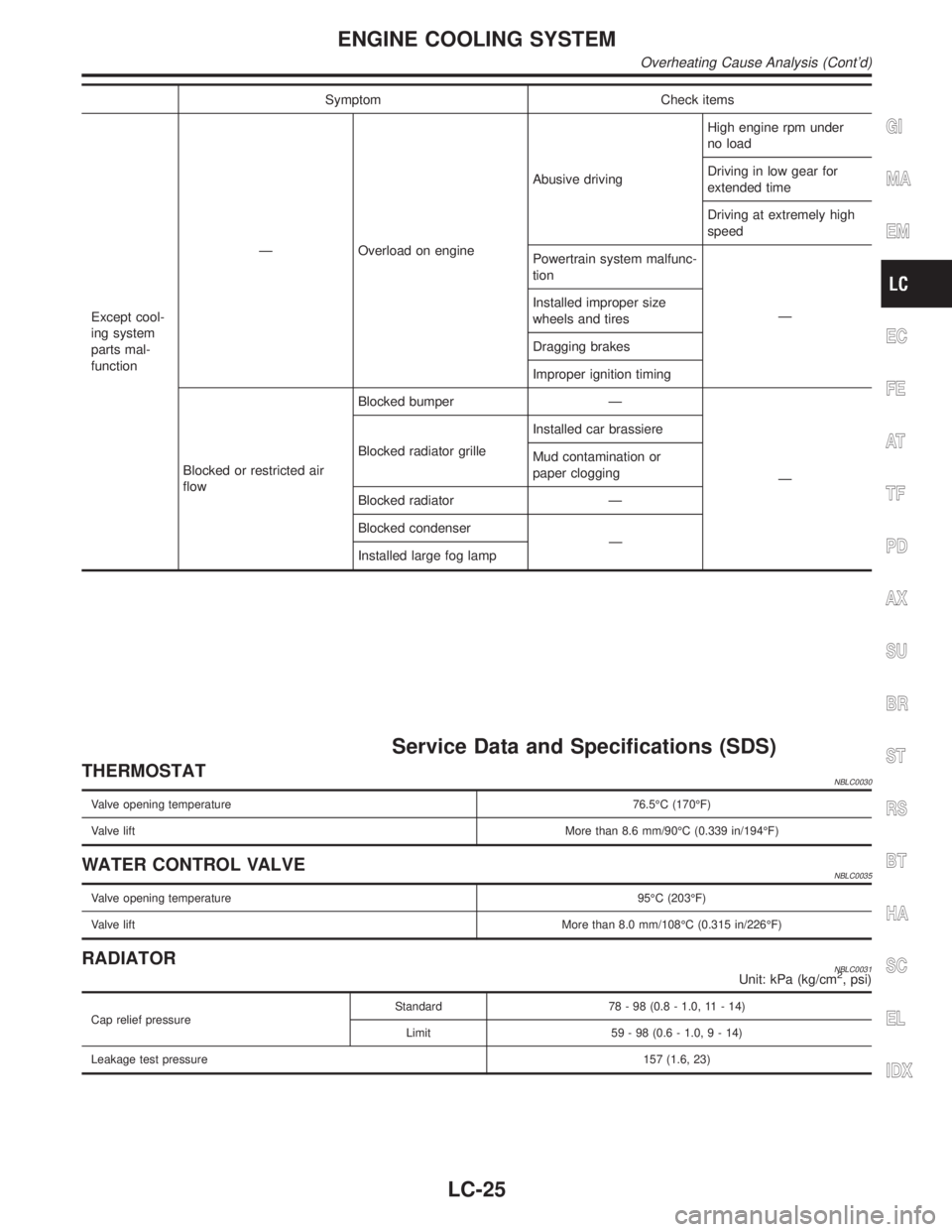
Service Data and Specifications (SDS)
THERMOSTATNBLC0030
Valve opening temperature76.5ÉC (170ÉF)
Valve liftMore than 8.6 mm/90ÉC (0.339 in/194ÉF)
WATER CONTROL VALVENBLC0035
Valve opening temperature95ÉC (203ÉF)
Valve liftMore than 8.0 mm/108ÉC (0.315 in/226ÉF)
RADIATORNBLC0031Unit: kPa (kg/cm2, psi)
Cap relief pressureStandard 78 - 98 (0.8 - 1.0, 11 - 14)
Limit 59 - 98 (0.6 - 1.0,9-14)
Leakage test pressure157 (1.6, 23)
GI
MA
EM
EC
FE
AT
TF
PD
AX
SU
BR
ST
RS
BT
HA
SC
EL
IDX
ENGINE COOLING SYSTEM
Overheating Cause Analysis (Cont'd)
LC-25
Page 1996 of 2395

MAINTENANCE
SECTION
MA
CONTENTS
PRECAUTIONS...............................................................2
Supplemental Restraint System (SRS)²AIR
BAG²and²SEAT BELT PRE-TENSIONER²...............2
PREPARATION...............................................................3
Special Service Tool ....................................................3
Commercial Service Tool .............................................3
GENERAL MAINTENANCE............................................4
PERIODIC MAINTENANCE............................................6
Schedule 1 ...................................................................7
EMISSION CONTROL SYSTEM MAINTENANCE.........7
CHASSIS AND BODY MAINTENANCE........................8
Schedule 2 ...................................................................9
EMISSION CONTROL SYSTEM MAINTENANCE.........9
CHASSIS AND BODY MAINTENANCE......................10
RECOMMENDED FLUIDS AND LUBRICANTS........... 11
Fluids and Lubricants ................................................ 11
SAE Viscosity Number ..............................................12
GASOLINE ENGINE OIL..........................................12
GEAR OIL...............................................................12
Anti-freeze Coolant Mixture Ratio .............................12
ENGINE MAINTENANCE..............................................13
Checking Drive Belts .................................................13
Changing Engine Coolant..........................................14
-DRAINING ENGINE COOLANT-..............................14
-REFILLING ENGINE COOLANT-..............................15
-FLUSHING COOLING SYSTEM-..............................16
Checking Fuel Lines ..................................................16
Changing Fuel Filter ..................................................16
WITH CONSULT-II..............................................16
WITHOUT CONSULT-II.......................................17
Changing Air Cleaner Filter .......................................17
VISCOUS PAPER TYPE...........................................17
Changing Engine Oil..................................................18
Changing Oil Filter .....................................................18
Changing Spark Plugs ...............................................19
Checking EVAP Vapor Lines .....................................20
CHASSIS AND BODY MAINTENANCE.......................21
Checking Exhaust System.........................................21
Checking A/T Fluid ....................................................21
Changing A/T Fluid ....................................................21Checking All-mode 4WD Transfer Fluid ....................22
Changing All-mode 4WD Transfer Fluid ....................22
Checking Propeller Shaft ...........................................23
Greasing Propeller Shaft ...........................................23
Checking Differential Gear Oil ...................................23
Changing Differential Gear Oil ..................................24
LIMITED-SLIP DIFFERENTIAL GEAR........................24
Balancing Wheels ......................................................24
Tire Rotation ..............................................................24
Checking Brake Fluid Level and Leaks.....................25
Checking Brake Lines and Cables ............................25
Checking Disc Brake .................................................25
ROTOR...................................................................25
CALIPER.................................................................25
PAD........................................................................25
Checking Drum Brake ...............................................26
WHEEL CYLINDER..................................................26
DRUM.....................................................................26
LINING....................................................................26
TEMPORARY METHOD FOR CHECKING LINING
WEAR
.....................................................................26
Checking Steering Gear, Linkage and Transfer
Gear ...........................................................................26
STEERING GEAR....................................................26
STEERING LINKAGE...............................................26
STEERING TRANSFER GEAR..................................26
Checking Power Steering Fluid and Lines ................27
CHECKING FLUID LEVEL........................................27
CHECKING LINES...................................................27
Lubricating Locks, Hinges and Hood Latches...........27
Checking Seat Belts, Buckles, Retractors,
Anchors and Adjusters...............................................28
SERVICE DATA AND SPECIFICATIONS (SDS).........29
Engine Maintenance ..................................................29
DRIVE BELT DEFLECTION......................................29
DRIVE BELT TENSION............................................29
SPARK PLUG TYPE................................................29
Chassis and Body Maintenance ................................29
WHEEL BALANCE...................................................29
GI
EM
LC
EC
FE
AT
TF
PD
AX
SU
BR
ST
RS
BT
HA
SC
EL
IDX
Page 1998 of 2395

Special Service ToolNBMA0002The actual shapes of Kent-Moore tools may differ from those of special service tools illustrated here.
Tool number
(Kent-Moore No.)
Tool nameDescription
KV10115801
(J38956)
Oil filter cap wrench
NT375
Removing oil filter
a: 64.3 mm (2.531 in)
Commercial Service ToolNBMA0041
Tool name
(Kent-Moore No.)Description
Belt tension gauge
(BT3373-F)
AMA126
Checking drive belt tension
GI
EM
LC
EC
FE
AT
TF
PD
AX
SU
BR
ST
RS
BT
HA
SC
EL
IDX
PREPARATION
Special Service Tool
MA-3
Page 2000 of 2395

ItemReference page
Brake pedal and
boosterCheck the pedal for smooth operation and make sure it has the proper dis-
tance under it when depressed fully. Check the brake booster function. Be
sure to keep floor mats away from the pedal.BR-14, ªBrake Pedal and
Bracketº and BR-19,
ªBrake Boosterº
Parking brakeCheck that the lever has the proper travel and make sure that the vehicle is
held securely on a fairly steep hill when only the parking brake is applied.BR-31, ªParking Brake
Controlº
Automatic transmis-
sion ªParkº mecha-
nismCheck that the lock release button on the selector lever operates properly
and smoothly. On a fairly steep hill check that the vehicle is held securely
with the selector lever in the ªPº position without applying any brakes.Ð
UNDER THE HOOD AND VEHICLE
The maintenance items listed here should be checked periodically (e.g. each time you check the engine oil or refuel).
ItemReference page
Windshield washer
fluidCheck that there is adequate fluid in the tank. Ð
Engine coolant levelCheck the coolant level when the engine is cold. MA-15
Radiator and hosesCheck the front of the radiator and clean off any dirt, insects, leaves, etc.,
that may have accumulated. Make sure the hoses have no cracks,
deformation, deterioration or loose connections.Ð
Brake fluid levelsMake sure that the brake fluid levels are between the ªMAXº and ªMINº lines
on the reservoir.MA-25
BatteryCheck the fluid level in each cell. It should be between the ªMAXº and ªMINº
lines.Ð
Engine drive beltsMake sure that no belt is frayed, worn, cracked or oily. MA-13
Engine oil levelCheck the level on the dipstick after parking the vehicle on a level spot and
turning off the engine.MA-18
Power steering fluid
level and linesCheck the level on the dipstick with the engine off. Check the lines for
improper attachment, leaks, cracks, etc.MA-27
Automatic transmis-
sion fluid levelCheck the level on the dipstick after putting the selector lever in ªPº with the
engine idling.MA-21
Exhaust systemMake sure there are no loose supports, cracks or holes. If the sound of the
exhaust seems unusual or there is a smell of exhaust fumes, immediately
locate the trouble and correct it.MA-21
UnderbodyThe underbody is frequently exposed to corrosive substances such as those
used on icy roads or to control dust. It is very important to remove these
substances, otherwise rust will form on the floor pan, frame, fuel lines and
around the exhaust system. At the end of winter, the underbody should be
thoroughly flushed with plain water, being careful to clean those areas where
mud and dirt can easily accumulate.Ð
Fluid leaksCheck under the vehicle for fuel, oil, water or other fluid leaks after the
vehicle has been parked for a while. Water dripping from the air conditioner
after use is normal. If you should notice any leaks or gasoline fumes are
evident, check for the cause and correct it immediately.Ð
GI
EM
LC
EC
FE
AT
TF
PD
AX
SU
BR
ST
RS
BT
HA
SC
EL
IDX
GENERAL MAINTENANCE
MA-5
Page 2002 of 2395
![INFINITI QX4 2001 Factory Service Manual Schedule 1NBMA0004S01EMISSION CONTROL SYSTEM MAINTENANCENBMA0004S0101
Abbreviations: R = Replace. I = Inspect. Correct or replace if necessary. [ ]: At the mileage intervals only
MAINTENANCE OPERATION INFINITI QX4 2001 Factory Service Manual Schedule 1NBMA0004S01EMISSION CONTROL SYSTEM MAINTENANCENBMA0004S0101
Abbreviations: R = Replace. I = Inspect. Correct or replace if necessary. [ ]: At the mileage intervals only
MAINTENANCE OPERATION](/img/42/57027/w960_57027-2001.png)
Schedule 1NBMA0004S01EMISSION CONTROL SYSTEM MAINTENANCENBMA0004S0101
Abbreviations: R = Replace. I = Inspect. Correct or replace if necessary. [ ]: At the mileage intervals only
MAINTENANCE OPERATIONMAINTENANCE INTERVAL
Reference
Section
- Page or
- Content Title Perform at number of miles, kilo-
meters or months, whichever
comes first.Miles x 1,000
(km x 1,000)
Months3.75
(6)
37.5
(12)
611.25
(18)
915
(24)
1218.75
(30)
1522.5
(36)
1826.25
(42)
2130
(48)
2433.75
(54)
2737.5
(60)
3041.25
(66)
3345
(72)
3648.75
(78)
3952.5
(84)
4256.25
(90)
4560
(96)
48
Drive beltsI* I* MA-13
Air cleaner filter NOTE (1) [R] [R] MA-17
EVAP vapor linesI* I* MA-20
Fuel linesI* I* MA-16
Fuel filter* NOTE (2)MA-16
Engine coolant NOTE (3)R* MA-14
Engine oil RRRRRRRRRRRRRRRRMA-18
Engine oil filter (Use part No.
15208-31U00 or equivalent.)RRRRRRRRRRRRRRRRMA-18
Spark plugs (PLATINUM-TIPPED
type)Replace every 105,000 miles (169,000 km) MA-19
Intake & exhaust valve clearance* NOTE (4)EM-52, ªValve
Clearanceº
NOTE:
(1) If operating mainly in dusty conditions, more frequent maintenance may be required.
(2) When the filter becomes clogged, the vehicle speed cannot be increased as the driver wishes. In such an event, replace the filter.
(3) After 60,000 miles (96,000 km) or 48 months, replace every 30,000 miles (48,000 km) or 24 months.
(4) If valve noise increases, inspect valve clearance.
HMaintenance items and intervals with ª*º are recommended by INFINITI for reliable vehicle operation. The owner need not perform such maintenance in order to maintain the
emission warranty or manufacturer recall liability. Other maintenance items and intervals are required.
GI
EM
LC
EC
FE
AT
TF
PD
AX
SU
BR
ST
RS
BT
HA
SC
EL
IDX
PERIODIC MAINTENANCE
Schedule 1
MA-7