lock INFINITI QX4 2001 Factory Service Manual
[x] Cancel search | Manufacturer: INFINITI, Model Year: 2001, Model line: QX4, Model: INFINITI QX4 2001Pages: 2395, PDF Size: 43.2 MB
Page 646 of 2395
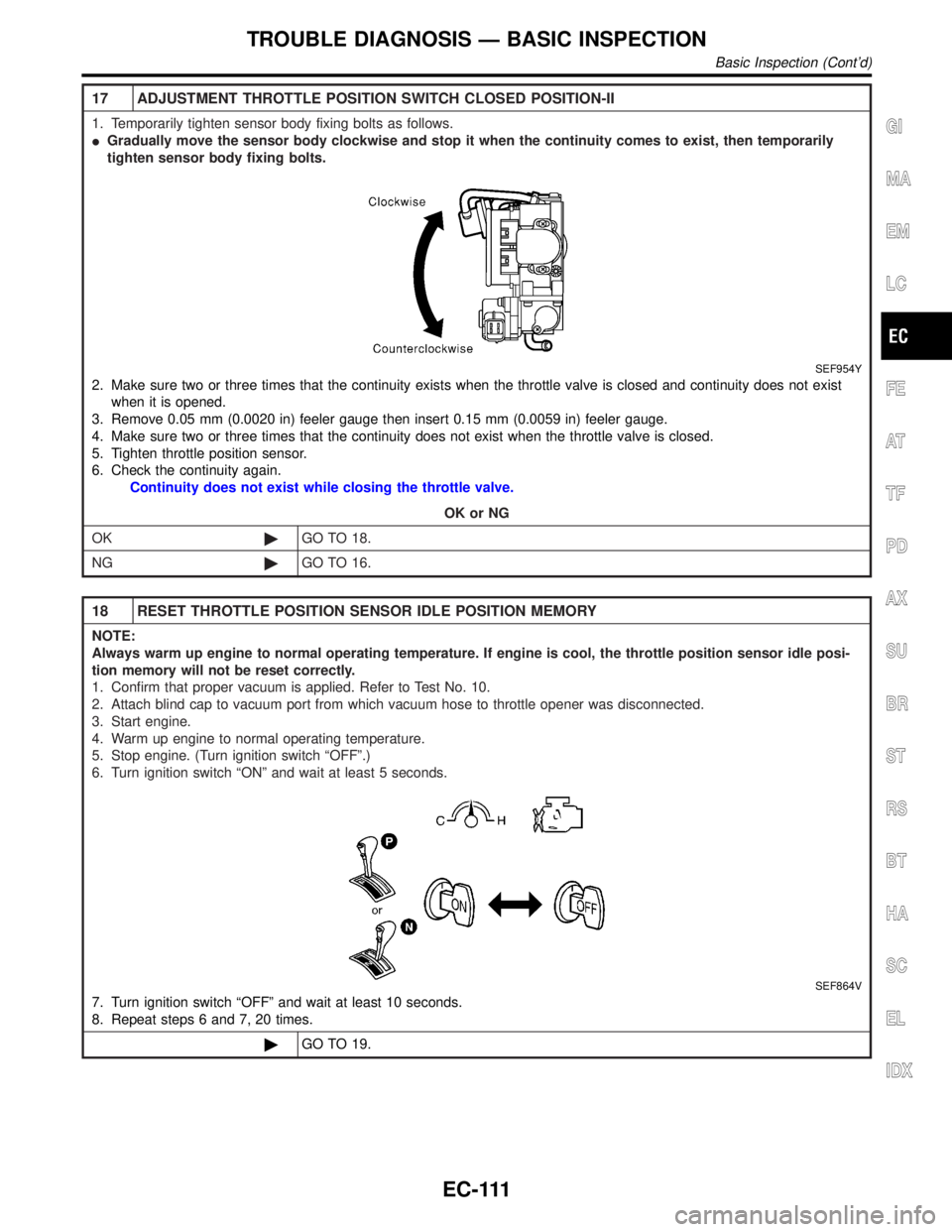
17 ADJUSTMENT THROTTLE POSITION SWITCH CLOSED POSITION-II
1. Temporarily tighten sensor body fixing bolts as follows.
IGradually move the sensor body clockwise and stop it when the continuity comes to exist, then temporarily
tighten sensor body fixing bolts.
SEF954Y
2. Make sure two or three times that the continuity exists when the throttle valve is closed and continuity does not exist
when it is opened.
3. Remove 0.05 mm (0.0020 in) feeler gauge then insert 0.15 mm (0.0059 in) feeler gauge.
4. Make sure two or three times that the continuity does not exist when the throttle valve is closed.
5. Tighten throttle position sensor.
6. Check the continuity again.
Continuity does not exist while closing the throttle valve.
OK or NG
OK©GO TO 18.
NG©GO TO 16.
18 RESET THROTTLE POSITION SENSOR IDLE POSITION MEMORY
NOTE:
Always warm up engine to normal operating temperature. If engine is cool, the throttle position sensor idle posi-
tion memory will not be reset correctly.
1. Confirm that proper vacuum is applied. Refer to Test No. 10.
2. Attach blind cap to vacuum port from which vacuum hose to throttle opener was disconnected.
3. Start engine.
4. Warm up engine to normal operating temperature.
5. Stop engine. (Turn ignition switch ªOFFº.)
6. Turn ignition switch ªONº and wait at least 5 seconds.
SEF864V
7. Turn ignition switch ªOFFº and wait at least 10 seconds.
8. Repeat steps 6 and 7, 20 times.
©GO TO 19.
GI
MA
EM
LC
FE
AT
TF
PD
AX
SU
BR
ST
RS
BT
HA
SC
EL
IDX
TROUBLE DIAGNOSIS Ð BASIC INSPECTION
Basic Inspection (Cont'd)
EC-111
Page 655 of 2395
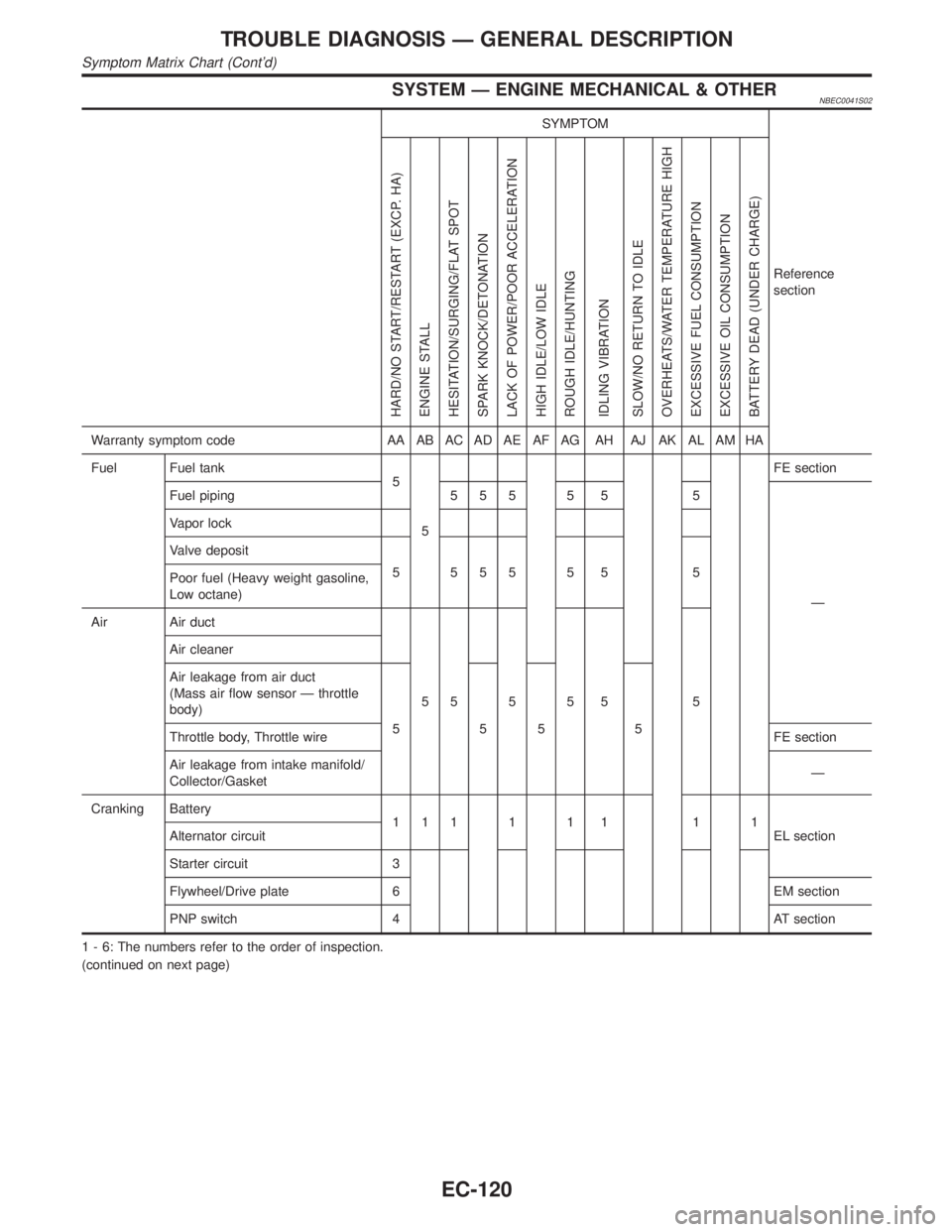
SYSTEM Ð ENGINE MECHANICAL & OTHERNBEC0041S02
SYMPTOM
Reference
section
HARD/NO START/RESTART (EXCP. HA)
ENGINE STALL
HESITATION/SURGING/FLAT SPOT
SPARK KNOCK/DETONATION
LACK OF POWER/POOR ACCELERATION
HIGH IDLE/LOW IDLE
ROUGH IDLE/HUNTING
IDLING VIBRATION
SLOW/NO RETURN TO IDLE
OVERHEATS/WATER TEMPERATURE HIGH
EXCESSIVE FUEL CONSUMPTION
EXCESSIVE OIL CONSUMPTION
BATTERY DEAD (UNDER CHARGE)
Warranty symptom code AA AB AC AD AE AF AG AH AJ AK AL AM HA
Fuel Fuel tank
5
5FE section
Fuel piping 5 5 5 5 5 5
Ð Vapor lock
Valve deposit
5 555 5 5 5
Poor fuel (Heavy weight gasoline,
Low octane)
Air Air duct
55555 5 Air cleaner
Air leakage from air duct
(Mass air flow sensor Ð throttle
body)
555 5
Throttle body, Throttle wireFE section
Air leakage from intake manifold/
Collector/GasketÐ
Cranking Battery
111111 11
EL section Alternator circuit
Starter circuit 3
Flywheel/Drive plate 6 EM section
PNP switch 4 AT section
1 - 6: The numbers refer to the order of inspection.
(continued on next page)
TROUBLE DIAGNOSIS Ð GENERAL DESCRIPTION
Symptom Matrix Chart (Cont'd)
EC-120
Page 656 of 2395
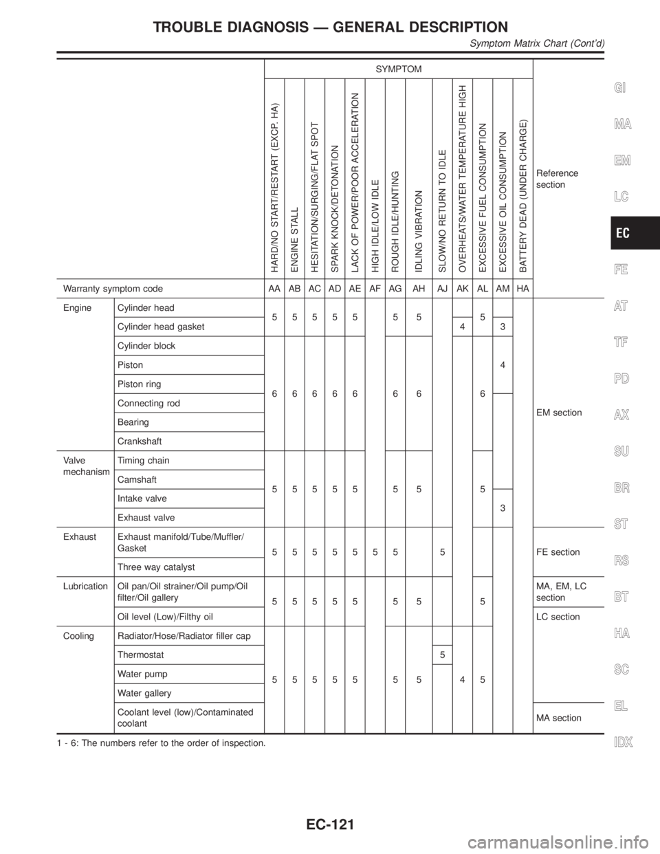
SYMPTOM
Reference
section
HARD/NO START/RESTART (EXCP. HA)
ENGINE STALL
HESITATION/SURGING/FLAT SPOT
SPARK KNOCK/DETONATION
LACK OF POWER/POOR ACCELERATION
HIGH IDLE/LOW IDLE
ROUGH IDLE/HUNTING
IDLING VIBRATION
SLOW/NO RETURN TO IDLE
OVERHEATS/WATER TEMPERATURE HIGH
EXCESSIVE FUEL CONSUMPTION
EXCESSIVE OIL CONSUMPTION
BATTERY DEAD (UNDER CHARGE)
Warranty symptom code AA AB AC AD AE AF AG AH AJ AK AL AM HA
Engine Cylinder head
55555 5 5 5
EM section Cylinder head gasket 4 3
Cylinder block
66666 6 6 64 Piston
Piston ring
Connecting rod
Bearing
Crankshaft
Valve
mechanismTiming chain
55555 5 5 5 Camshaft
Intake valve
3
Exhaust valve
Exhaust Exhaust manifold/Tube/Muffler/
Gasket
5555555 5 FEsection
Three way catalyst
Lubrication Oil pan/Oil strainer/Oil pump/Oil
filter/Oil gallery
55555 5 5 5MA, EM, LC
section
Oil level (Low)/Filthy oilLC section
Cooling Radiator/Hose/Radiator filler cap
55555 5 5 45 Thermostat 5
Water pump
Water gallery
Coolant level (low)/Contaminated
coolantMA section
1 - 6: The numbers refer to the order of inspection.
GI
MA
EM
LC
FE
AT
TF
PD
AX
SU
BR
ST
RS
BT
HA
SC
EL
IDX
TROUBLE DIAGNOSIS Ð GENERAL DESCRIPTION
Symptom Matrix Chart (Cont'd)
EC-121
Page 780 of 2395

2 DETECT MALFUNCTIONING PART
Check the following.
IHarness connectors M32, F23
IFuse block (J/B) connector M10
I15A fuse
IHarness for open or short between heated oxygen sensor 1 (front) and fuse
©Repair harness or connectors.
3 CHECK HO2S1 (FRONT) OUTPUT CIRCUIT FOR OPEN AND SHORT
1. Turn ignition switch ªOFFº.
2. Disconnect ECM harness connector.
3. Check harness continuity between ECM terminal and HO2S1 terminal as follows.
Refer to Wiring Diagram.
MTBL0520
Continuity should exist.
4. Also check harness for short to ground and short to power.
OK or NG
OK©GO TO 4.
NG©Repair open circuit or short to ground or short to power in harness or connectors.
4 CHECK HEATED OXYGEN SENSOR 1 HEATER (FRONT)
Check resistance between HO2S1 (front) terminals as follows.
SEF969Y
CAUTION:
Discard any heated oxygen sensor which has been dropped from a height of more than 0.5 m (19.7 in) onto a
hard surface such as a concrete floor; use a new one.
OK or NG
OK©GO TO 6.
NG©GO TO 5.
GI
MA
EM
LC
FE
AT
TF
PD
AX
SU
BR
ST
RS
BT
HA
SC
EL
IDX
DTC P0135, P0155 HEATED OXYGEN SENSOR 1 HEATER (FRONT) (BANK
1)/(BANK 2)
Diagnostic Procedure (Cont'd)
EC-245
Page 826 of 2395

Diagnostic ProcedureNBEC0168
1 CHECK HO2S2 (REAR) POWER SUPPLY CIRCUIT
1. Turn ignition switch ªOFFº.
2. Check heated oxygen sensor harness 2 (rear) protector color.
SEF372Z
3. Disconnect corresponding heated oxygen sensor 2 (rear) harness connector.
SEF971Y
4. Turn ignition switch ªONº.
5. Check voltage between HO2S2 terminal 3 and ground.
SEF314X
OK or NG
OK©GO TO 3.
NG©GO TO 2.
2 DETECT MALFUNCTIONING PART
Check the following.
IHarness connectors M32, F23
IFuse block (J/B) connector M10
I15A fuse
IHarness for open or short between heated oxygen sensor 2 (rear) and fuse
©Repair harness or connectors.
GI
MA
EM
LC
FE
AT
TF
PD
AX
SU
BR
ST
RS
BT
HA
SC
EL
IDX
DTC P0141, P0161 HEATED OXYGEN SENSOR 2 HEATER (REAR) (BANK 1)/
(BANK 2)
Diagnostic Procedure
EC-291
Page 849 of 2395
On Board Diagnosis LogicNBEC0610This diagnosis checks whether the engine coolant temperature is
extraordinary high, even when the load is not heavy.
When malfunction is detected, the malfunction indicator lamp (MIL)
will light up even in the first trip.
Malfunction is detected when engine coolant temperature is exces-
sively high under normal engine speed.
Possible CauseNBEC0611IThermostat
IImproper ignition timing
IEngine coolant temperature sensor
IBlocked radiator
IBlocked front end (Improper fitting of nose mask)
ICrushed vehicle frontal area (Vehicle frontal is collided but not
repaired)
IBlocked air passage by improper installation of front fog lamp
or fog lamps.
IImproper mixture ratio of coolant
IDamaged bumper
For more information, refer to ªMAIN 12 CAUSES OF
OVERHEATINGº, EC-319.
Overall Function CheckNBEC0612Use this procedure to check the overall function of the coolant
overtemperature enrichment protection check, a DTC might not be
confirmed.
WARNING:
Never remove the radiator cap when the engine is hot. Serious
burns could be caused by high-pressure fluid escaping from
the radiator.
Wrap a thick cloth around the cap. Carefully remove the cap
by turning it a quarter turn to allow built-up pressure to
escape. Then turn the cap all the way off.
SEF621W
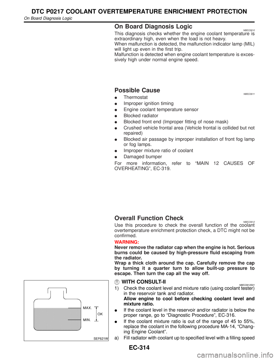
WITH CONSULT-IINBEC0612S011) Check the coolant level and mixture ratio (using coolant tester)
in the reservoir tank and radiator.
Allow engine to cool before checking coolant level and
mixture ratio.
IIf the coolant level in the reservoir and/or radiator is below the
proper range, go to ªDiagnostic Procedureº, EC-316.
IIf the coolant mixture ratio is out of the range of 45 to 55%,
replace the coolant in the following procedure MA-14, ªChang-
ing Engine Coolantº.
a) Fill radiator with coolant up to specified level with a filling speed
DTC P0217 COOLANT OVERTEMPERATURE ENRICHMENT PROTECTION
On Board Diagnosis Logic
EC-314
Page 850 of 2395

of 2 liters per minute like pouring coolant from a kettle. Be sure
to use coolant with the proper mixture ratio. Refer to MA-12,
ªAnti-freeze Coolant Mixture Ratioº.
b) After refilling coolant, run engine to ensure that no water-flow
noise is emitted.
c) After checking or replacing coolant, go to step 3 below.
2) Ask the customer if engine coolant has been added. If it has
been added, go to ªDiagnostic Procedureº, EC-316. After
repair, go to the next step.
3) Start engine and let it idle.
4) Make sure that A/C switch is ªOFFº and air conditioner is not
operating. If NG, check air conditioner circuit. Refer to HA-30
or HA-35, ªTROUBLE DIAGNOSESº. After repair, go to the
next step.
5) Check for blocked coolant passage.
a) Warm up engine to normal operating temperature, then grasp
radiator upper hose and lower hose and make sure that cool-
ant flows.
If NG, go to ªDiagnostic Procedureº, EC-316. After repair, go
to the next step.
Be extremely careful not to touch any moving or adjacent
parts.
6) Check for blocked radiator air passage.
a) When market fog lamps have been installed, check for dam-
aged fans and clogging in the condenser and radiator.
b) Check the front end for clogging caused by insects or debris.
c) Check for improper fitting of front-end cover, damaged radia-
tor grille or bumper, damaged vehicle front.
If NG, take appropriate action and then go to the next step.
7) Check function of ECT sensor.
Refer to step 7 of ªDiagnostic Procedureº, EC-316.
If NG, replace ECT sensor and go to the next step.
8) Check ignition timing. Refer to basic inspection, EC-101.
Make sure that ignition timing is 15ɱ5É at idle.
If NG, adjust ignition timing and then recheck.
WITH GSTNBEC0612S021) Check the coolant level and mixture ratio (using coolant tester)
in the reservoir tank and radiator.
Allow engine to cool before checking coolant level and
mixture ratio.
IIf the coolant level in the reservoir and/or radiator is below the
proper range, and go to ªDiagnostic Procedureº, EC-316.
IIf the coolant mixture ratio is out of the range of 45 to 55%,
replace the coolant in the following procedure MA-14, ªChang-
ing Engine Coolantº.
a) Fill radiator with coolant up to specified level with a filling speed
of 2 liters per minute like pouring coolant from a kettle. Be sure
to use coolant with the proper mixture ratio. Refer to MA-12,
ªAnti-freeze Coolant Mixture Ratioº.
b) After refilling coolant, run engine to ensure that no water-flow
noise is emitted.
c) After checking or replacing coolant, go to step 3 below.
2) Ask the customer if engine coolant has been added. If it has
been added, go to ªDiagnostic Procedureº, EC-316. After
repair, go to the next step.
3) Start engine and let it idle.
GI
MA
EM
LC
FE
AT
TF
PD
AX
SU
BR
ST
RS
BT
HA
SC
EL
IDX
DTC P0217 COOLANT OVERTEMPERATURE ENRICHMENT PROTECTION
Overall Function Check (Cont'd)
EC-315
Page 851 of 2395
4) Make sure that A/C switch is ªOFFº and air conditioner is not
operating. If NG, check air conditioner circuit. Refer to HA-35
or HA-30, ªTROUBLE DIAGNOSESº. After repair, go to the
next step.
5) Check for blocked coolant passage.
a) Warm up engine to normal operating temperature, then grasp
radiator upper hose and lower hose and make sure that cool-
ant flows.
If NG, go to ªDiagnostic Procedureº, EC-316. After repair, go
to the next step.
Be extremely careful not to touch any moving or adjacent
parts.
6) Check for blocked radiator air passage.
a) When market fog lamps have been installed, check for dam-
aged fans and clogging in the condenser and radiator.
b) Check the front end for clogging caused by insects or debris.
c) Check for improper fitting of front-end cover, damaged radia-
tor grille or bumper, damaged vehicle front.
If NG, take appropriate action and then go to the next step.
7) Check function of ECT sensor.
Refer to step 6 of ªDiagnostic Procedureº, EC-316.
If NG, replace ECT sensor and go to the next step.
8) Check ignition timing. Refer to basic inspection, EC-101.
Make sure that ignition timing is 15ɱ5É at idle.
If NG, adjust ignition timing and then recheck.
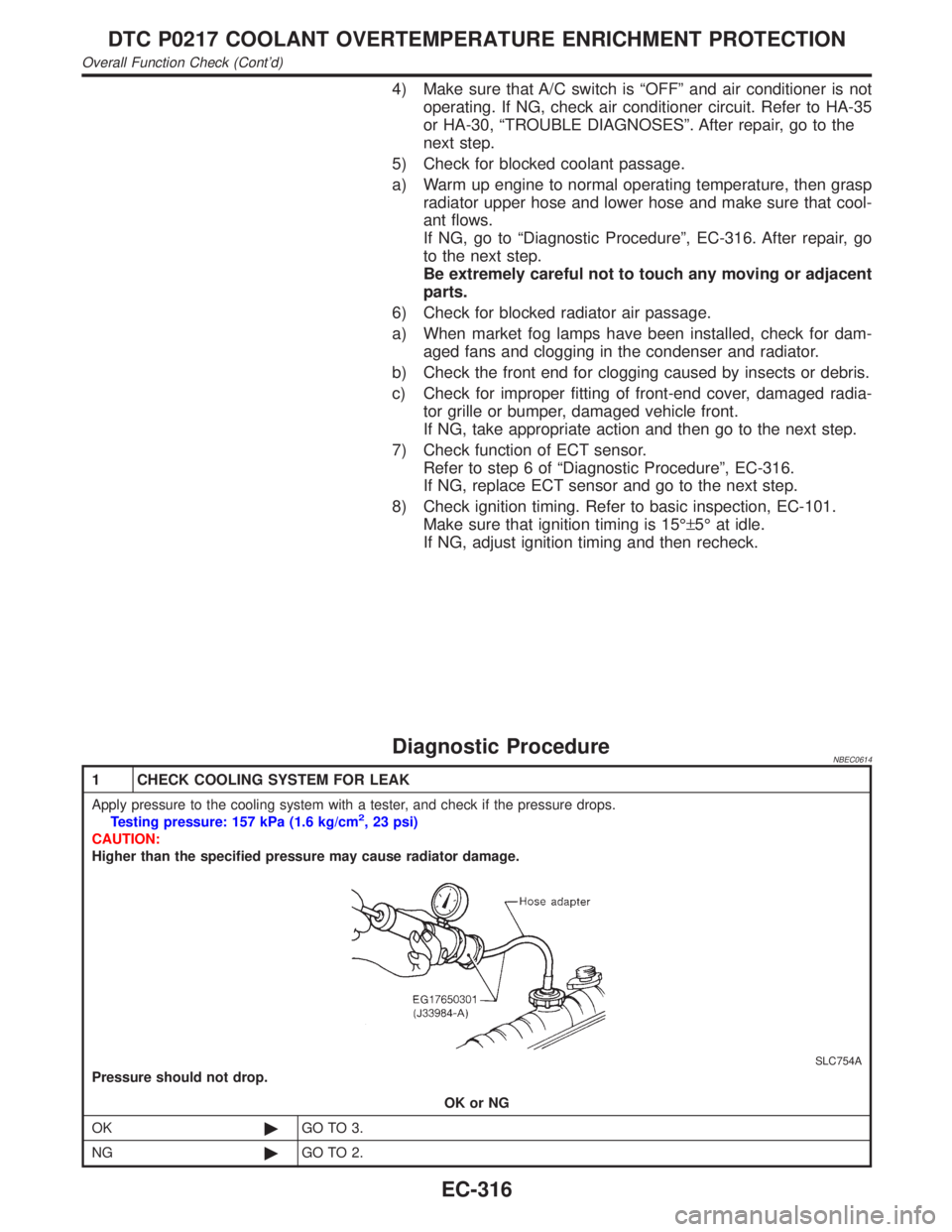
Diagnostic ProcedureNBEC0614
1 CHECK COOLING SYSTEM FOR LEAK
Apply pressure to the cooling system with a tester, and check if the pressure drops.
Testing pressure: 157 kPa (1.6 kg/cm2, 23 psi)
CAUTION:
Higher than the specified pressure may cause radiator damage.
SLC754A
Pressure should not drop.
OK or NG
OK©GO TO 3.
NG©GO TO 2.
DTC P0217 COOLANT OVERTEMPERATURE ENRICHMENT PROTECTION
Overall Function Check (Cont'd)
EC-316
Page 854 of 2395
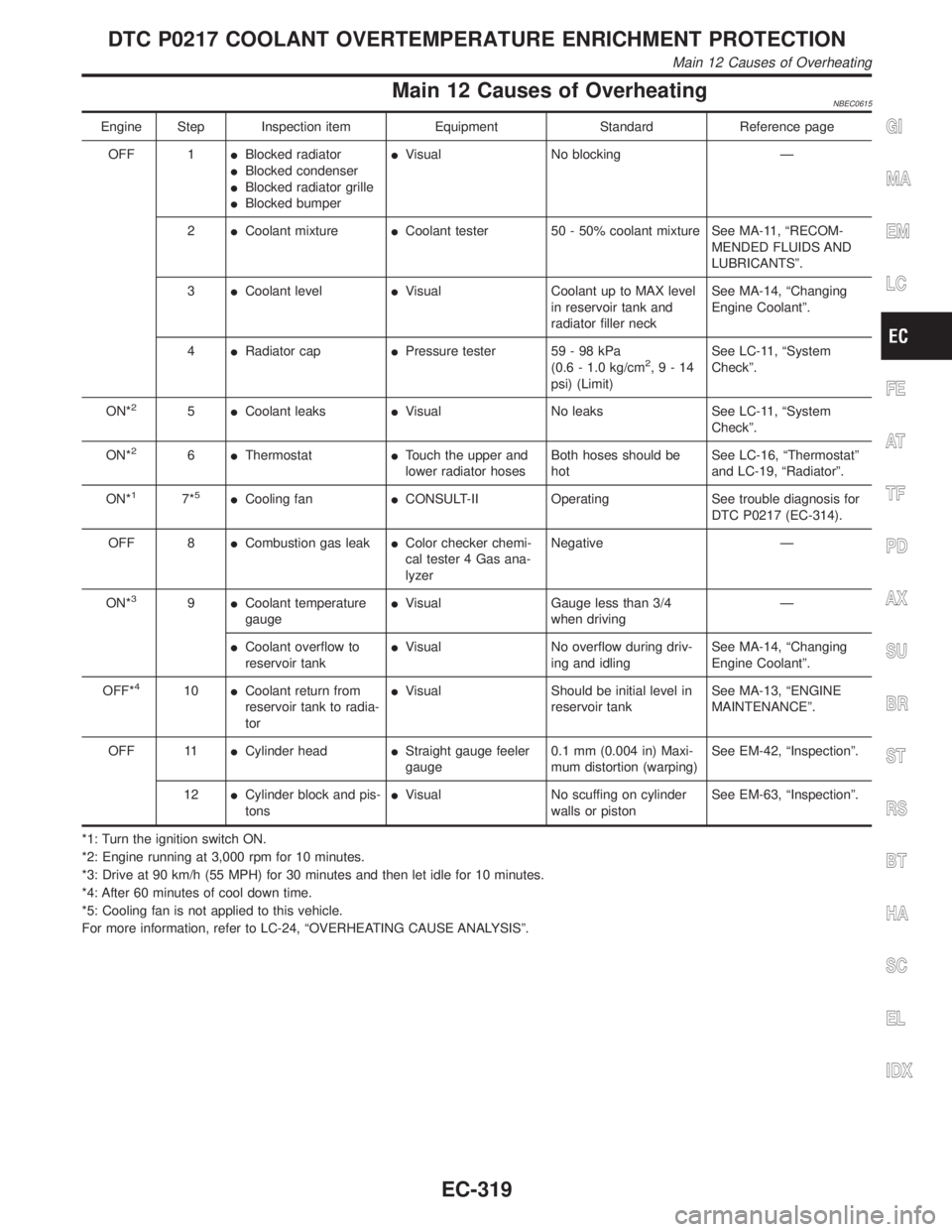
Main 12 Causes of OverheatingNBEC0615
Engine Step Inspection item Equipment Standard Reference page
OFF 1IBlocked radiator
IBlocked condenser
IBlocked radiator grille
IBlocked bumperIVisual No blocking Ð
2ICoolant mixtureICoolant tester 50 - 50% coolant mixture See MA-11, ªRECOM-
MENDED FLUIDS AND
LUBRICANTSº.
3ICoolant levelIVisual Coolant up to MAX level
in reservoir tank and
radiator filler neckSee MA-14, ªChanging
Engine Coolantº.
4IRadiator capIPressure tester 59 - 98 kPa
(0.6 - 1.0 kg/cm
2,9-14
psi) (Limit)See LC-11, ªSystem
Checkº.
ON*
25ICoolant leaksIVisual No leaks See LC-11, ªSystem
Checkº.
ON*
26IThermostatITouch the upper and
lower radiator hosesBoth hoses should be
hotSee LC-16, ªThermostatº
and LC-19, ªRadiatorº.
ON*
17*5ICooling fanICONSULT-II Operating See trouble diagnosis for
DTC P0217 (EC-314).
OFF 8ICombustion gas leakIColor checker chemi-
cal tester 4 Gas ana-
lyzerNegative Ð
ON*
39ICoolant temperature
gaugeIVisual Gauge less than 3/4
when drivingÐ
ICoolant overflow to
reservoir tankIVisual No overflow during driv-
ing and idlingSee MA-14, ªChanging
Engine Coolantº.
OFF*
410ICoolant return from
reservoir tank to radia-
torIVisual Should be initial level in
reservoir tankSee MA-13, ªENGINE
MAINTENANCEº.
OFF 11ICylinder headIStraight gauge feeler
gauge0.1 mm (0.004 in) Maxi-
mum distortion (warping)See EM-42, ªInspectionº.
12ICylinder block and pis-
tonsIVisual No scuffing on cylinder
walls or pistonSee EM-63, ªInspectionº.
*1: Turn the ignition switch ON.
*2: Engine running at 3,000 rpm for 10 minutes.
*3: Drive at 90 km/h (55 MPH) for 30 minutes and then let idle for 10 minutes.
*4: After 60 minutes of cool down time.
*5: Cooling fan is not applied to this vehicle.
For more information, refer to LC-24, ªOVERHEATING CAUSE ANALYSISº.
GI
MA
EM
LC
FE
AT
TF
PD
AX
SU
BR
ST
RS
BT
HA
SC
EL
IDX
DTC P0217 COOLANT OVERTEMPERATURE ENRICHMENT PROTECTION
Main 12 Causes of Overheating
EC-319
Page 863 of 2395

SEF332I
Component DescriptionNBEC0185The knock sensor is attached to the cylinder block. It senses
engine knocking using a piezoelectric element. A knocking vibration
from the cylinder block is sensed as vibrational pressure. This
pressure is converted into a voltage signal and sent to the ECM.
Freeze frame data will not be stored in the ECM for the knock
sensor. The MIL will not light for knock sensor malfunction.
The knock sensor has one trip detection logic.
ECM Terminals and Reference ValueNBEC0663Specification data are reference values and are measured between each terminal and ground.
CAUTION:
Do not use ECM ground terminals when measuring input/output voltage. Doing so may result in dam-
age to the ECM's transistor. Use a ground other than ECM terminals, such as the ground.
TERMI-
NAL
NO.WIRE
COLORITEM CONDITION DATA (DC Voltage)
93 W Knock sensor[Engine is running]
IIdle speedApproximately 2.5V
On Board Diagnosis LogicNBEC0187Malfunction is detected when an excessively low or high voltage
from the knock sensor is sent to ECM.
Possible CauseNBEC0491IHarness or connectors
(The knock sensor circuit is open or shorted.)
IKnock sensor
SEF058Y
DTC Confirmation ProcedureNBEC0188NOTE:
If ªDTC Confirmation Procedureº has been previously conducted,
always turn ignition switch ªOFFº and wait at least 10 seconds
before conducting the next test.
TESTING CONDITION:
Before performing the following procedure, confirm that bat-
tery voltage is more than 10V at idle.
DTC P0325 KNOCK SENSOR (KS)
Component Description
EC-328