lock INFINITI QX4 2001 Factory Manual PDF
[x] Cancel search | Manufacturer: INFINITI, Model Year: 2001, Model line: QX4, Model: INFINITI QX4 2001Pages: 2395, PDF Size: 43.2 MB
Page 354 of 2395

SAT983A
c. Install original thrust washer on oil pump. Place shim setting
gauge legs onto machined surface of oil pump assembly. Allow
gauging plunger to rest on thrust washer. Lock plunger in place
with set screw.
SAT984A
d. Use feeler gauge to measure gap between gauging plunger
and gauging cylinder. This measurement should give you exact
reverse clutch drum end play.
Reverse clutch drum end play ªT
2º:
0.55 - 0.90 mm (0.0217 - 0.0354 in)
IIf end play is out of specification, decrease or increase thick-
ness of oil pump thrust washer as necessary.
Available oil pump thrust washer:
Refer to SDS, AT-361.
SAT985A
Assembly (2)NBAT01571. Install brake band and band strut.
a. Install band strut on brake band.
IApply petroleum jelly to band strut.
SAT986A
b. Place brake band on periphery of reverse clutch drum, and
insert band strut into end of band servo piston stem.
SAT987A
c. Install anchor end bolt on transmission case. Then, tighten
anchor end bolt just enough so that reverse clutch drum (clutch
pack) will not tilt forward.
GI
MA
EM
LC
EC
FE
TF
PD
AX
SU
BR
ST
RS
BT
HA
SC
EL
IDX
ASSEMBLY
Adjustment (Cont'd)
AT-349
Page 356 of 2395

SAT993A
f. Install oil pump assembly.
IInstall two converter housing securing bolts in bolt holes
in oil pump assembly as guides.
SAT994A
IInsert oil pump assembly to the specified position in
transmission, as shown at left.
SAT114B
5. Install O-ring on input shaft.
IApply ATF to O-rings.
SAT397C
6. Install converter housing.
a. Apply recommended sealant (Genuine anaerobic liquid
gasket, Three Bond TB1215, Locktite Part No. 51813 or
equivalent) to outer periphery of bolt holes in converter hous-
ing.
IDo not apply too much sealant.
SAT158G
b. Apply recommended sealant (Genuine anaerobic liquid
gasket, Three Bond TB1215, Locktite Part No. 51813 or
equivalent) to seating surfaces of bolts that secure front of
converter housing.
c. Install converter housing on transmission case.
GI
MA
EM
LC
EC
FE
TF
PD
AX
SU
BR
ST
RS
BT
HA
SC
EL
IDX
ASSEMBLY
Assembly (2) (Cont'd)
AT-351
Page 357 of 2395

SAT001B
7. Install turbine revolution sensor.
8. Adjust brake band.
a. Tighten anchor end bolt to specified torque.
Anchor end bolt:
:4-6N´m(0.4 - 0.6 kg-m, 35 - 52 in-lb)
b. Back off anchor end bolt two and a half turns.
SAT002B
c. While holding anchor end bolt, tighten lock nut.
Ancher end bolt nut:
: 41 - 50 N´m (4.1 - 5.2 kg-m, 30 - 37 ft-lb)
SAT115B
9. Install terminal cord assembly.
a. Install O-ring on terminal cord assembly.
IApply petroleum jelly to O-ring.
b. Compress terminal cord assembly stopper and install terminal
cord assembly on transmission case.
SAT004BA
10. Install control valve assembly.
a. Install accumulator piston return springs B, C and D.
Free length of return springs:
Refer to SDS, AT-357.
SAT005B
b. Install manual valve on control valve.
IApply ATF to manual valve.
ASSEMBLY
Assembly (2) (Cont'd)
AT-352
Page 361 of 2395

General SpecificationsNBAT0160
Applied modelVQ35DE engine
2WD 4WD
Automatic transmission model RE4R01A
Transmission model code number 4EX16 4EX17
Stall torque ratio2.0:1
Transmission gear ratio1st 2.785
2nd 1.545
Top 1.000
OD 0.694
Reverse 2.272
Recommended fluidNissan Matic ªDº (Continental U.S. and Alaska) or Genuine Nissan Automatic Trans-
mission Fluid (Canada)*1
Fluid capacity8.5(9 US qt, 7-1/2 Imp qt)
*1: Refer to MA-11, ªFluids and Lubricantsº.
Shift ScheduleNBAT0178VEHICLE SPEED WHEN SHIFTING GEARS THROTTLE POSITIONNBAT0178S01
Throttle positionVehicle speed km/h (MPH)
D
1,D2D2,D3D3,D4D4,D3D3,D2D2,D112,11
Full throttle55-59
(34 - 37)105 - 113
(65 - 70)174 - 184
(108 - 114)170 - 180
(106 - 112)102 - 110
(63 - 68)43-47
(27 - 29)43-47
(27 - 29)
Half throttle37-41
(23 - 25)71-79
(44 - 49)129 - 139
(80 - 86)81-91
(50 - 57)33-41
(21 - 25)12-16
(7 - 10)43-47
(27 - 29)
VEHICLE SPEED WHEN PERFORMING AND RELEASING LOCK-UPNBAT0178S02
Throttle positionOverdrive control switch [Shift posi-
tion]Vehicle speed km/h (MPH)
Lock-up ªONº Lock-up ªOFFº
Full throttleON [D
4] 174 - 184 (108 - 114) 170 - 180 (106 - 112)
OFF [D
3] 104 - 114 (65 - 71) 101 - 111 (63 - 69)
Half throttleON [D
4] 151 - 161 (94 - 100) 106 - 116 (66 - 72)
OFF [D
3] 85-95(53-59) 82-92(51-57)
Stall RevolutionNBAT0163
Stall revolution rpm2,440 - 2,640
Line PressureNBAT0164
Engine speed
rpmLine pressure kPa (kg/cm2, psi)
D, 2 and 1 positions R position
Idle 422 - 461 (4.3 - 4.7, 61 - 67) 667 - 706 (6.8 - 7.2, 97 - 102)
Stall 1,020 - 1,098 (10.4 - 11.2, 148 - 159) 1,422 - 1,500 (14.5 - 15.3, 206 - 218)
SERVICE DATA AND SPECIFICATIONS (SDS)
General Specifications
AT-356
Page 366 of 2395

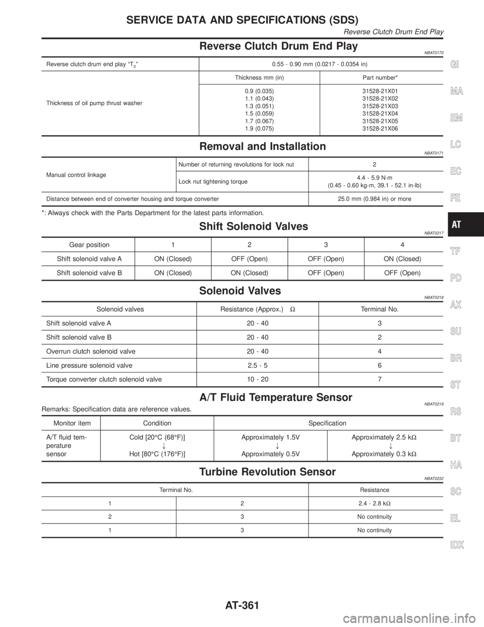
Reverse Clutch Drum End PlayNBAT0170
Reverse clutch drum end play ªT2º 0.55 - 0.90 mm (0.0217 - 0.0354 in)
Thickness of oil pump thrust washerThickness mm (in) Part number*
0.9 (0.035)
1.1 (0.043)
1.3 (0.051)
1.5 (0.059)
1.7 (0.067)
1.9 (0.075)31528-21X01
31528-21X02
31528-21X03
31528-21X04
31528-21X05
31528-21X06
Removal and InstallationNBAT0171
Manual control linkageNumber of returning revolutions for lock nut 2
Lock nut tightening torque4.4 - 5.9 N´m
(0.45 - 0.60 kg-m, 39.1 - 52.1 in-lb)
Distance between end of converter housing and torque converter 25.0 mm (0.984 in) or more
*: Always check with the Parts Department for the latest parts information.
Shift Solenoid ValvesNBAT0217
Gear position1234
Shift solenoid valve A ON (Closed) OFF (Open) OFF (Open) ON (Closed)
Shift solenoid valve B ON (Closed) ON (Closed) OFF (Open) OFF (Open)
Solenoid ValvesNBAT0218
Solenoid valves Resistance (Approx.)WTerminal No.
Shift solenoid valve A 20 - 40 3
Shift solenoid valve B 20 - 40 2
Overrun clutch solenoid valve 20 - 40 4
Line pressure solenoid valve 2.5 - 5 6
Torque converter clutch solenoid valve 10 - 20 7
A/T Fluid Temperature SensorNBAT0219Remarks: Specification data are reference values.
Monitor item Condition Specification
A/T fluid tem-
perature
sensorCold [20ÉC (68ÉF)]
"
Hot [80ÉC (176ÉF)]Approximately 1.5V
"
Approximately 0.5VApproximately 2.5 kW
"
Approximately 0.3 kW
Turbine Revolution SensorNBAT0232
Terminal No. Resistance
1 2 2.4 - 2.8 kW
2 3 No continuity
1 3 No continuity
GI
MA
EM
LC
EC
FE
TF
PD
AX
SU
BR
ST
RS
BT
HA
SC
EL
IDX
SERVICE DATA AND SPECIFICATIONS (SDS)
Reverse Clutch Drum End Play
AT-361
Page 369 of 2395

SBR686C
Precautions
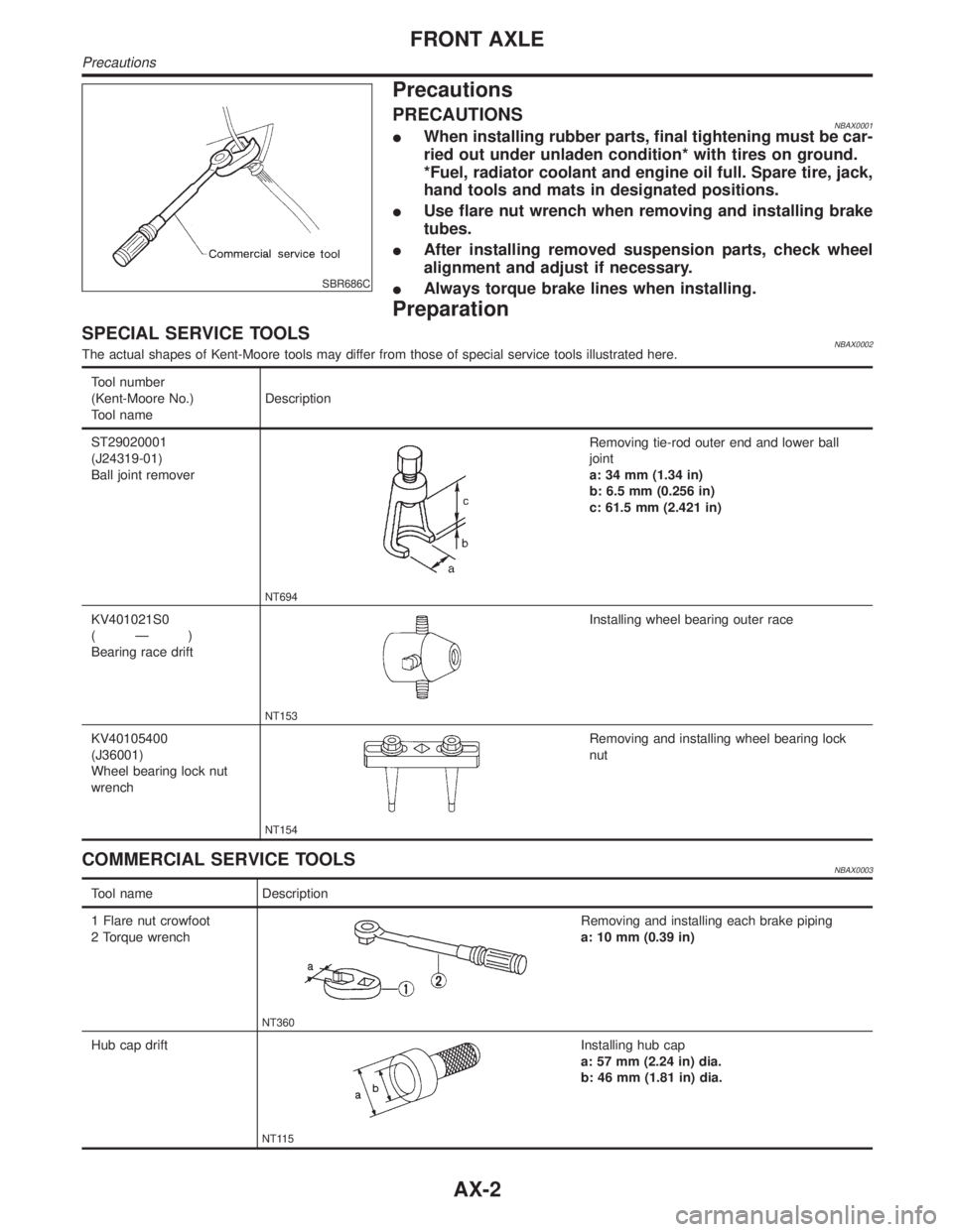
PRECAUTIONSNBAX0001IWhen installing rubber parts, final tightening must be car-
ried out under unladen condition* with tires on ground.
*Fuel, radiator coolant and engine oil full. Spare tire, jack,
hand tools and mats in designated positions.
IUse flare nut wrench when removing and installing brake
tubes.
IAfter installing removed suspension parts, check wheel
alignment and adjust if necessary.
IAlways torque brake lines when installing.
Preparation
SPECIAL SERVICE TOOLSNBAX0002The actual shapes of Kent-Moore tools may differ from those of special service tools illustrated here.
Tool number
(Kent-Moore No.)
Tool nameDescription
ST29020001
(J24319-01)
Ball joint remover
NT694
Removing tie-rod outer end and lower ball
joint
a: 34 mm (1.34 in)
b: 6.5 mm (0.256 in)
c: 61.5 mm (2.421 in)
KV401021S0
(Ð)
Bearing race drift
NT153
Installing wheel bearing outer race
KV40105400
(J36001)
Wheel bearing lock nut
wrench
NT154
Removing and installing wheel bearing lock
nut
COMMERCIAL SERVICE TOOLSNBAX0003
Tool name Description
1 Flare nut crowfoot
2 Torque wrench
NT360
Removing and installing each brake piping
a: 10 mm (0.39 in)
Hub cap drift
NT115
Installing hub cap
a: 57 mm (2.24 in) dia.
b: 46 mm (1.81 in) dia.
FRONT AXLE
Precautions
AX-2
Page 371 of 2395

SFA747B
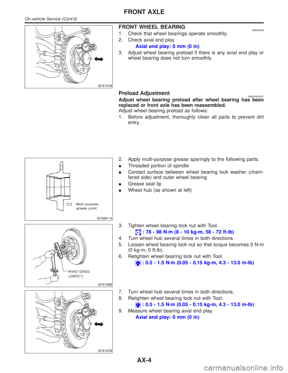
FRONT WHEEL BEARINGNBAX00051. Check that wheel bearings operate smoothly.
2. Check axial end play.
Axial end play: 0 mm (0 in)
3. Adjust wheel bearing preload if there is any axial end play or
wheel bearing does not turn smoothly.
Preload AdjustmentNBAX0005S01Adjust wheel bearing preload after wheel bearing has been
replaced or front axle has been reassembled.
Adjust wheel bearing preload as follows:
1. Before adjustment, thoroughly clean all parts to prevent dirt
entry.
SFA891-A
2. Apply multi-purpose grease sparingly to the following parts:
IThreaded portion of spindle
IContact surface between wheel bearing lock washer (cham-
fered side) and outer wheel bearing
IGrease seal lip
IWheel hub (as shown at left)
SFA748B
3. Tighten wheel bearing lock nut with Tool.
: 78 - 98 N´m (8 - 10 kg-m, 58 - 72 ft-lb)
4. Turn wheel hub several times in both directions.
5. Loosen wheel bearing lock nut so that torque becomes 0 N´m
(0 kg-m, 0 ft-lb).
6. Retighten wheel bearing lock nut with Tool.
: 0.5 - 1.5 N´m (0.05 - 0.15 kg-m, 4.3 - 13.0 in-lb)
SFA747B
7. Turn wheel hub several times in both directions.
8. Retighten wheel bearing lock nut with Tool.
: 0.5 - 1.5 N´m (0.05 - 0.15 kg-m, 4.3 - 13.0 in-lb)
9. Measure wheel bearing axial end play.
Axial end play: 0 mm (0 in)
FRONT AXLE
On-vehicle Service (Cont'd)
AX-4
Page 372 of 2395

SMA580A
10. Measure starting force ªAº at wheel hub bolt.
SFA830
11. Install lock washer by tightening the lock nut within 15 to 30
degrees.
12. Turn wheel hub several times in both directions to seat wheel
bearing correctly.
13. Measure starting force ªBº at wheel hub bolt. Refer to proce-
dure 10.
14. Wheel bearing preload ªCº can be calculated as shown below.
C=BþA
Wheel bearing preload ªCº:
7.06 - 20.99 N (0.72 - 2.14 kg, 1.59 - 4.72 lb)
15. If wheel bearing preload ªCº is outside specifications, remove
lock washer. Tighten or loosen lock nut within±15 degrees
(Refer to step 11 above). Install lock washer, then repeat steps
12, 13 and 14.
16. Repeat above procedures until correct axial end play and
wheel bearing preload are obtained.
17. Install drive flange and wheel hub cap.
SFA901
DRIVE SHAFTNBAX0006ICheck boot and drive shaft for cracks, wear, damage and
grease leakage.
GI
MA
EM
LC
EC
FE
AT
TF
PD
SU
BR
ST
RS
BT
HA
SC
EL
IDX
FRONT AXLE
On-vehicle Service (Cont'd)
AX-5
Page 374 of 2395

SFA802B
2. Remove hub cap with suitable tool.
SFA753B
3. Remove snap ring with suitable tool.
4. Remove drive flange.
SFA364BA
5. Remove lock washer.
SFA754B
6. Remove wheel bearing lock nut.
SFA832
7. Remove wheel hub and wheel bearing.
Be careful not to drop outer bearing.
INSTALLATIONNBAX00091. After installing wheel hub and wheel bearing, adjust wheel
bearing preload.
Refer to ªPreload Adjustmentº, ªFRONT WHEEL BEARINGº,
ªOn-vehicle Serviceº, AX-4.
GI
MA
EM
LC
EC
FE
AT
TF
PD
SU
BR
ST
RS
BT
HA
SC
EL
IDX
FRONT AXLE
Wheel Hub and Rotor Disc (Cont'd)
AX-7
Page 381 of 2395

SFA443B
6. Lock new larger boot band securely with a suitable tool, then
lock new smaller boot band.
7. Install new plug seal to slide joint housing by lightly tapping it.
Apply sealant to mating surface of plug seal.
SFA800
Wheel Side (ZF100)NBAX0020S021. Install new small boot band and boot on drive shaft.
Cover drive shaft serration with tape so as not to damage boot
during installation.
SFA884
2. Set joint assembly onto drive shaft by lightly tapping it.
Install joint assembly securely, ensuring marks which were
made during disassembly are properly aligned.
SFA473BA
3. Pack drive shaft with specified amount of grease.
Specified amount of grease:
135 - 145 g (4.76 - 5.11 oz)
4. Make sure that boot is properly installed on the drive shaft
groove. Set boot so that it does not swell and deform when its
length is ªL
2º.
Length ªL
2º: 96 - 98 mm (3.78 - 3.86 in)
5. Lock new larger boot band securely with a suitable tool.
6. Lock new smaller boot band.
SFA887
INSTALLATIONNBAX00211. Apply multi-purpose grease.
FRONT AXLE
Drive Shaft (Cont'd)
AX-14