lock INFINITI QX4 2001 Factory Manual Online
[x] Cancel search | Manufacturer: INFINITI, Model Year: 2001, Model line: QX4, Model: INFINITI QX4 2001Pages: 2395, PDF Size: 43.2 MB
Page 382 of 2395
SFA846-A
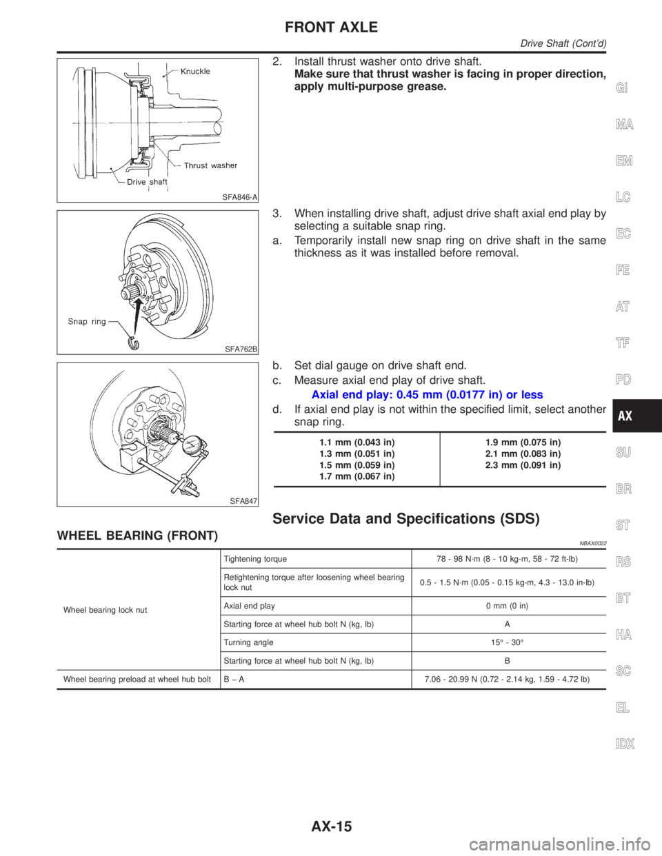
2. Install thrust washer onto drive shaft.
Make sure that thrust washer is facing in proper direction,
apply multi-purpose grease.
SFA762B
3. When installing drive shaft, adjust drive shaft axial end play by
selecting a suitable snap ring.
a. Temporarily install new snap ring on drive shaft in the same
thickness as it was installed before removal.
SFA847
b. Set dial gauge on drive shaft end.
c. Measure axial end play of drive shaft.
Axial end play: 0.45 mm (0.0177 in) or less
d. If axial end play is not within the specified limit, select another
snap ring.
1.1 mm (0.043 in)
1.3 mm (0.051 in)
1.5 mm (0.059 in)
1.7 mm (0.067 in)1.9 mm (0.075 in)
2.1 mm (0.083 in)
2.3 mm (0.091 in)
Service Data and Specifications (SDS)
WHEEL BEARING (FRONT)NBAX0022
Wheel bearing lock nutTightening torque 78 - 98 N´m (8 - 10 kg-m, 58 - 72 ft-lb)
Retightening torque after loosening wheel bearing
lock nut0.5 - 1.5 N´m (0.05 - 0.15 kg-m, 4.3 - 13.0 in-lb)
Axial end play 0 mm (0 in)
Starting force at wheel hub bolt N (kg, lb) A
Turning angle 15É - 30É
Starting force at wheel hub bolt N (kg, lb) B
Wheel bearing preload at wheel hub bolt B þ A 7.06 - 20.99 N (0.72 - 2.14 kg, 1.59 - 4.72 lb)
GI
MA
EM
LC
EC
FE
AT
TF
PD
SU
BR
ST
RS
BT
HA
SC
EL
IDX
FRONT AXLE
Drive Shaft (Cont'd)
AX-15
Page 384 of 2395
SBR686C
Precautions
PRECAUTIONSNBAX0023IWhen installing rubber parts, final tightening must be car-
ried out under unladen condition* with tires on ground.
*Fuel, radiator coolant and engine oil full. Spare tire, jack,
hand tools and mats in designated positions.
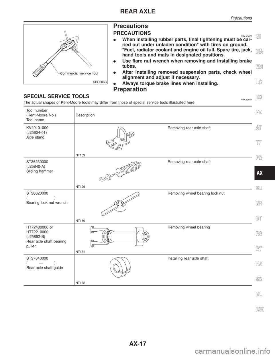
IUse flare nut wrench when removing and installing brake
tubes.
IAfter installing removed suspension parts, check wheel
alignment and adjust if necessary.
IAlways torque brake lines when installing.
Preparation
SPECIAL SERVICE TOOLSNBAX0024The actual shapes of Kent-Moore tools may differ from those of special service tools illustrated here.
Tool number
(Kent-Moore No.)
Tool nameDescription
KV40101000
(J25604-01)
Axle stand
NT159
Removing rear axle shaft
ST36230000
(J25840-A)
Sliding hammer
NT126
Removing rear axle shaft
ST38020000
(Ð)
Bearing lock nut wrench
NT160
Removing wheel bearing lock nut
HT72480000 or
HT72210000
(J25852-B)
Rear axle shaft bearing
puller
NT161
Removing wheel bearing
ST37840000
(Ð)
Rear axle shaft guide
NT162
Installing rear axle shaft
GI
MA
EM
LC
EC
FE
AT
TF
PD
SU
BR
ST
RS
BT
HA
SC
EL
IDX
REAR AXLE
Precautions
AX-17
Page 387 of 2395
SRA759A
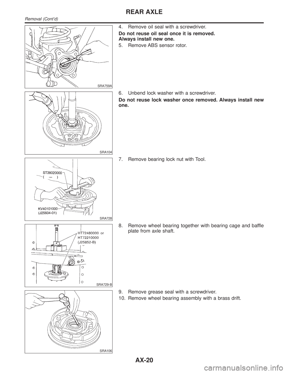
4. Remove oil seal with a screwdriver.
Do not reuse oil seal once it is removed.
Always install new one.
5. Remove ABS sensor rotor.
SRA104
6. Unbend lock washer with a screwdriver.
Do not reuse lock washer once removed. Always install new
one.
SRA728
7. Remove bearing lock nut with Tool.
SRA729-B
8. Remove wheel bearing together with bearing cage and baffle
plate from axle shaft.
SRA106
9. Remove grease seal with a screwdriver.
10. Remove wheel bearing assembly with a brass drift.
REAR AXLE
Removal (Cont'd)
AX-20
Page 388 of 2395
InspectionNBAX0030AXLE SHAFTNBAX0030S01Check axle shaft for straightness, cracks, damage, wear and dis-
tortion. Replace if necessary.
BEARING CAGENBAX0030S02Check bearing cage for deformation and cracks. Replace if neces-
sary.
REAR AXLE HOUSINGNBAX0030S03Check rear axle housing for yield, deformation and cracks. Replace
if necessary.
SRA288A
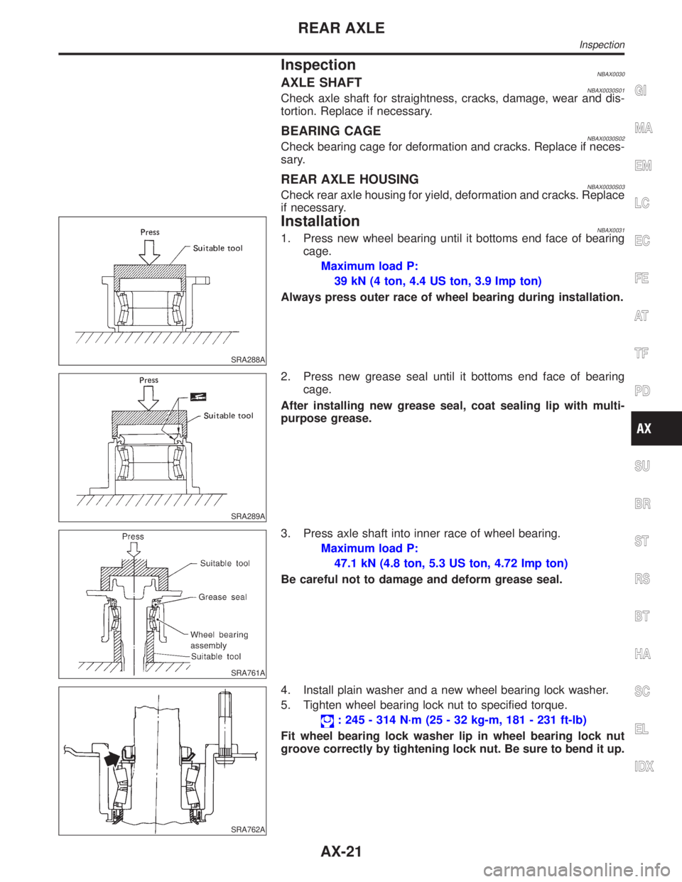
InstallationNBAX00311. Press new wheel bearing until it bottoms end face of bearing
cage.
Maximum load P:
39 kN (4 ton, 4.4 US ton, 3.9 Imp ton)
Always press outer race of wheel bearing during installation.
SRA289A
2. Press new grease seal until it bottoms end face of bearing
cage.
After installing new grease seal, coat sealing lip with multi-
purpose grease.
SRA761A
3. Press axle shaft into inner race of wheel bearing.
Maximum load P:
47.1 kN (4.8 ton, 5.3 US ton, 4.72 Imp ton)
Be careful not to damage and deform grease seal.
SRA762A
4. Install plain washer and a new wheel bearing lock washer.
5. Tighten wheel bearing lock nut to specified torque.
: 245 - 314 N´m (25 - 32 kg-m, 181 - 231 ft-lb)
Fit wheel bearing lock washer lip in wheel bearing lock nut
groove correctly by tightening lock nut. Be sure to bend it up.
GI
MA
EM
LC
EC
FE
AT
TF
PD
SU
BR
ST
RS
BT
HA
SC
EL
IDX
REAR AXLE
Inspection
AX-21
Page 389 of 2395
SRA763A
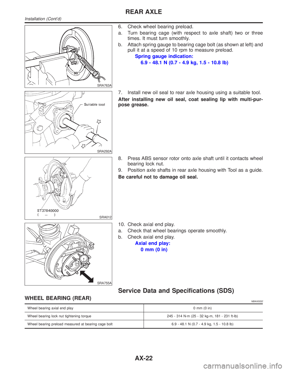
6. Check wheel bearing preload.
a. Turn bearing cage (with respect to axle shaft) two or three
times. It must turn smoothly.
b. Attach spring gauge to bearing cage bolt (as shown at left) and
pull it at a speed of 10 rpm to measure preload.
Spring gauge indication:
6.9 - 48.1 N (0.7 - 4.9 kg, 1.5 - 10.8 lb)
SRA292A
7. Install new oil seal to rear axle housing using a suitable tool.
After installing new oil seal, coat sealing lip with multi-pur-
pose grease.
SRA012
8. Press ABS sensor rotor onto axle shaft until it contacts wheel
bearing lock nut.
9. Position axle shafts in rear axle housing with Tool as a guide.
Be careful not to damage oil seal.
SRA755A
10. Check axial end play.
a. Check that wheel bearings operate smoothly.
b. Check axial end play.
Axial end play:
0mm(0in)
Service Data and Specifications (SDS)
WHEEL BEARING (REAR)NBAX0032
Wheel bearing axial end play0mm(0in)
Wheel bearing lock nut tightening torque 245 - 314 N´m (25 - 32 kg-m, 181 - 231 ft-lb)
Wheel bearing preload measured at bearing cage bolt 6.9 - 48.1 N (0.7 - 4.9 kg, 1.5 - 10.8 lb)
REAR AXLE
Installation (Cont'd)
AX-22
Page 399 of 2395

SBR992
RemovalNBBR0011CAUTION:
IBe careful not to splash brake fluid on painted areas; it
may cause paint damage. If brake fluid is splashed on
painted areas, wash it away with water immediately.
IAll hoses must be free from excessive bending, twisting
and pulling.
1. Connect vinyl tube to air bleeder valve.
2. Drain brake fluid from each air bleeder valve by depressing
brake pedal.
3. Remove flare nut connecting brake tube and hose, then with-
draw lock spring.
4. Cover openings to prevent entrance of dirt whenever discon-
necting brake line.
InspectionNBBR0012Check brake lines (tubes and hoses) for cracks, deterioration or
other damage. Replace any damaged parts.
SBR686C
InstallationNBBR0013CAUTION:
IRefill with new brake fluid ªDOT 3º.
INever reuse drained brake fluid.
1. Tighten all flare nuts and connecting bolts.
Flare nut:
: 15 - 17 N´m (1.5 - 1.8 kg-m, 11 - 13 ft-lb)
Connecting bolt:
: 17 - 19 N´m (1.7 - 2.0 kg-m, 12 - 14 ft-lb)
2. Refill until new brake fluid comes out of each air bleeder valve.
3. Bleed air. Refer to ªBleeding Brake Systemº, BR-8.
BRAKE HYDRAULIC LINE
Removal
BR-10
Page 404 of 2395

SBR824B
1. Loosen lock nut and adjust pedal free height by turning brake
booster input rod. Then tighten lock nut.
Make sure that tip of input rod stays inside.
2. Adjust clearance ªC
1º and ªC2º with stop lamp switch and
ASCD switch respectively. Then tighten lock nuts.
3. Check pedal free play.
Make sure that stop lamp is off when pedal is released.
4. Check brake pedal's depressed height while engine is running.
If depressed height is below specified value, check brake sys-
tem for leaks, accumulation of air or any damage to compo-
nents (master cylinder, wheel cylinder, etc.). Then make nec-
essary repairs.
GI
MA
EM
LC
EC
FE
AT
TF
PD
AX
SU
ST
RS
BT
HA
SC
EL
IDX
BRAKE PEDAL AND BRACKET
Adjustment (Cont'd)
BR-15
Page 409 of 2395

SBR116BG
Installation=NBBR0027CAUTION:
IBe careful not to deform or bend brake pipes during instal-
lation of booster.
IReplace clevis pin if damaged.
IRefill with new brake fluid ªDOT 3º.
INever reuse drained brake fluid.
ITake care not to damage brake booster mounting bolt
thread when installing. Due to the narrow angle of
installation, the threads can be damaged by the dash
panel.
1. Before fitting booster, temporarily adjust clevis to dimension
shown.
2. Fit booster, then secure mounting nuts (brake pedal bracket to
brake booster) lightly.
3. Connect brake pedal and booster input rod with clevis pin.
4. Secure mounting nuts.
Specification: 13 - 16 N´m (1.3 - 1.6 kg-m,9-12ft-lb)
5. Install master cylinder. Refer to ªInstallationº in ªMASTER
CYLINDERº, BR-18.
6. Adjust brake pedal height and free play. Refer to ªAdjustmentº
in ªBRAKE PEDAL AND BRACKETº, BR-14.
7. Secure lock nut for clevis.
: 16 - 22 N´m (1.6 - 2.2 kg-m, 12 - 16 ft-lb)
8. Bleed air. Refer to ªBleeding Brake Systemº, BR-8.
BRAKE BOOSTER
Installation
BR-20
Page 421 of 2395

PurposeNBBR0087The Anti-Lock Brake System (ABS) consists of electronic and hydraulic components. It allows for control of
braking force so locking of the wheels can be avoided.
1) Improves proper tracking performance through steering wheel operation.
2) Eases obstacle avoidance through steering wheel operation.
3) Improves vehicle stability.
OperationNBBR0088IWhen the vehicle speed is less than 10 km/h (6 MPH) this system does not work.
IThe Anti-Lock Brake System (ABS) has a self-test function. The system turns on the ABS warning lamp
for 1 second each time the ignition switch is turned ªONº. After the engine is started, the ABS warning lamp
turns off. The system performs a test the first time the vehicle reaches 6 km/h (4 MPH). A mechanical noise
may be heard as the ABS performs this self-test. This is a normal part of the self-test feature. If a mal-
function is found during this check, the ABS warning lamp will stay on.
IWhile driving, a mechanical noise may be heard during ABS operation. This is a normal condition.
ABS Hydraulic CircuitNBBR0089
SBR859D
1. Inlet solenoid valve
2. Outlet solenoid valve
3. Reservoir4. Pump
5. Motor
6. Inlet valve7. Outlet valve
8. Bypass check valve
9. Damper
DESCRIPTIONABS
Purpose
BR-32
Page 477 of 2395
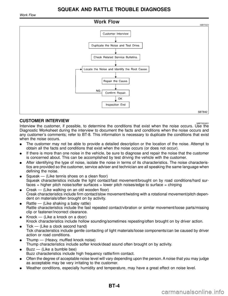
Work FlowNBBT0024
SBT842
CUSTOMER INTERVIEWNBBT0024S01Interview the customer, if possible, to determine the conditions that exist when the noise occurs. Use the
Diagnostic Worksheet during the interview to document the facts and conditions when the noise occurs and
any customer's comments; refer to BT-8. This information is necessary to duplicate the conditions that exist
when the noise occurs.
IThe customer may not be able to provide a detailed description or the location of the noise. Attempt to
obtain all the facts and conditions that exist when the noise occurs (or does not occur).
IIf there is more than one noise in the vehicle, be sure to diagnose and repair the noise that the customer
is concerned about. This can be accomplished by test driving the vehicle with the customer.
IAfter identifying the type of noise, isolate the noise in terms of its characteristics. The noise characteris-
tics are provided so the customer, service adviser and technician are all speaking the same language when
defining the noise.
ISqueak Ð (Like tennis shoes on a clean floor)
Squeak characteristics include the light contact/fast movement/brought on by road conditions/hard sur-
faces = higher pitch noise/softer surfaces = lower pitch noises/edge to surface = chirping
ICreak Ð (Like walking on an old wooden floor)
Creak characteristics include firm contact/slow movement/twisting with a rotational movement/pitch depen-
dent on materials/often brought on by activity.
IRattle Ð (Like shaking a baby rattle)
Rattle characteristics include the fast repeated contact/vibration or similar movement/loose parts/missing
clip or fastener/incorrect clearance.
IKnock Ð (Like a knock on a door)
Knock characteristics include hollow sounding/sometimes repeating/often brought on by driver action.
ITick Ð (Like a clock second hand)
Tick characteristics include gentle contacting of light materials/loose components/can be caused by driver
action or road conditions.
IThump Ð (Heavy, muffled knock noise)
Thump characteristics include softer knock/dead sound often brought on by activity.
IBuzz Ð (Like a bumble bee)
Buzz characteristics include high frequency rattle/firm contact.
IOften the degree of acceptable noise level will vary depending upon the person. A noise that you may judge
as acceptable may be very irritating to the customer.
IWeather conditions, especially humidity and temperature, may have a great effect on noise level.
SQUEAK AND RATTLE TROUBLE DIAGNOSES
Work Flow
BT-4