timing INFINITI QX4 2001 Factory Service Manual
[x] Cancel search | Manufacturer: INFINITI, Model Year: 2001, Model line: QX4, Model: INFINITI QX4 2001Pages: 2395, PDF Size: 43.2 MB
Page 1676 of 2395

SEM439G
SEM440G
17. Install RH and LH rocker covers.
Rocker cover tightening procedure:
ITighten in numerical order as shown in the figure.
a. Tighten bolts 1 to 10 in that order to 6.9 to 8.8 N´m (0.7 to 0.9
kg-m, 61 to 78 in-lb).
b. Then tighten bolts 1 to 10 as indicated in figure to 6.9 to 8.8
N´m (0.7 to 0.9 kg-m, 61 to 78 in-lb).
18. Hang engine using the right and left side engine slingers with
a suitable hoist.
19. Set a suitable transmission jack under the suspension mem-
ber.
20. Remove right and left side engine mounting nuts.
21. Remove right and left side suspension member bolts.
22. Install aluminum oil pan. Refer to EM-18, ªInstallationº.
23. Set ring gear stopper using the mounting bolt hole.
IBe careful not to damage the signal plate teeth.
SEM417G
24. Install crankshaft pulley to crankshaft.
IAlign pointer with TDC mark on crankshaft pulley.
SEM531G
25. Install crankshaft pulley bolt.
ILubricate thread and seat surface of the bolt with new
engine oil.
a. Tighten to 39 to 49 N´m (4.0 to 5.0 kg-m, 29 to 36 ft-lb).
b. Put a paint mark on the crankshaft pulley.
SEM963E
c. Again tighten by turning 60É to 66É, about the angle from one
hexagon bolt head corner to another.
26. Install camshaft position sensor (PHASE), crankshaft position
sensors (REF)/(POS) and CVTC sensors.
27. Reinstall removed parts in the reverse order of removal.
IWhen installing fuel tube and intake manifold collectors, refer
to EM-12, ªTIGHTENING PROCEDURESº.
IAfter starting engine, keep idling for three minutes. Then
rev engine up to 3,000 rpm under no load to purge air from
the high-pressure chamber of the chain tensioners. The
engine may produce a rattling noise. This indicates that
GI
MA
LC
EC
FE
AT
TF
PD
AX
SU
BR
ST
RS
BT
HA
SC
EL
IDX
TIMING CHAIN
Installation (Cont'd)
EM-33
Page 1677 of 2395
air still remains in the chamber and is not a matter of
concern.
TIMING CHAIN
Installation (Cont'd)
EM-34
Page 1678 of 2395
SEM948E
ReplacementNBEM0015CAUTION:
When removing the oil pans, oil pump assembly and timing
chain from engine, first remove the camshaft position sensor
(PHASE), CVTC sensor and the crankshaft position sensors
(REF)/(POS) from the assembly.
Be careful not to damage sensor edges.
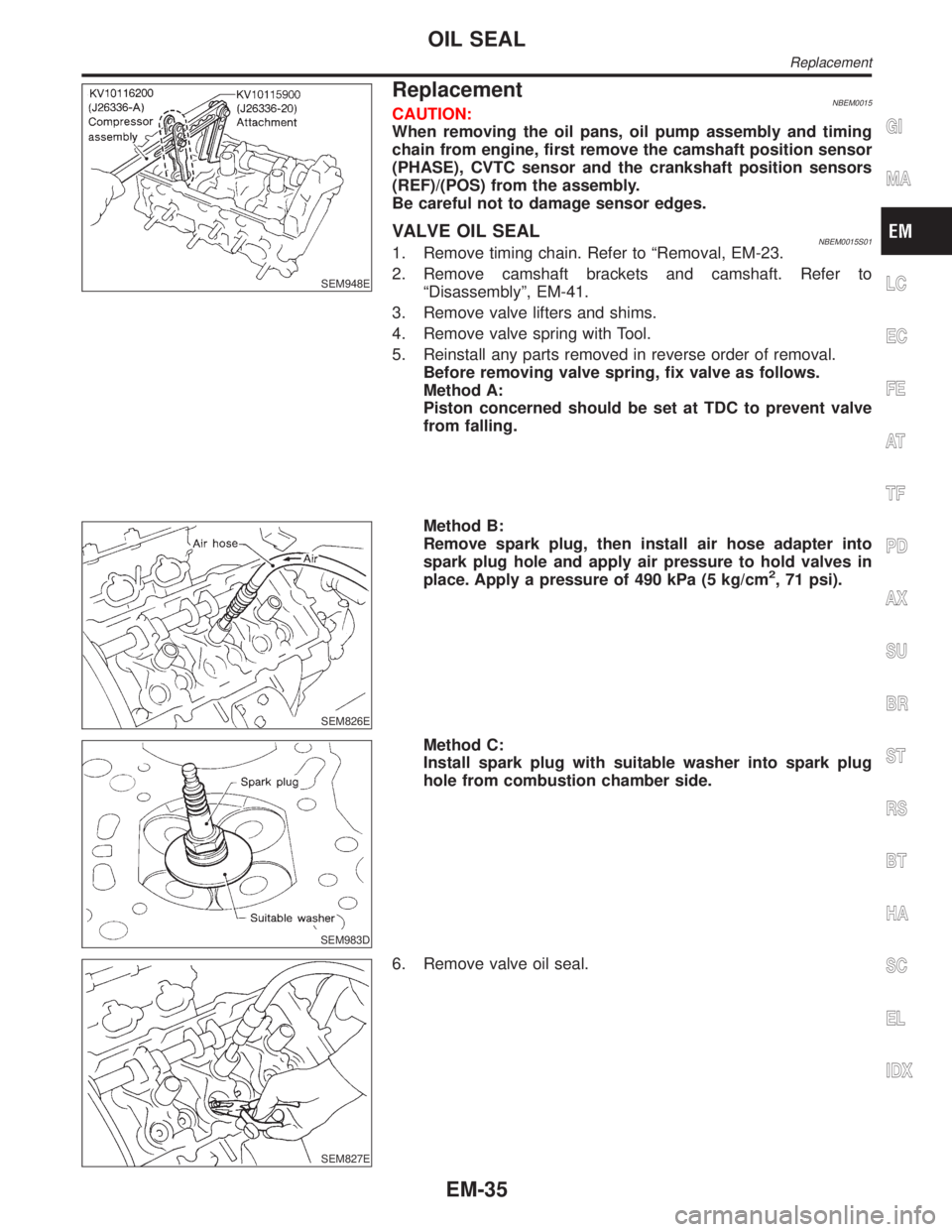
VALVE OIL SEALNBEM0015S011. Remove timing chain. Refer to ªRemoval, EM-23.
2. Remove camshaft brackets and camshaft. Refer to
ªDisassemblyº, EM-41.
3. Remove valve lifters and shims.
4. Remove valve spring with Tool.
5. Reinstall any parts removed in reverse order of removal.
Before removing valve spring, fix valve as follows.
Method A:
Piston concerned should be set at TDC to prevent valve
from falling.
SEM826E
Method B:
Remove spark plug, then install air hose adapter into
spark plug hole and apply air pressure to hold valves in
place. Apply a pressure of 490 kPa (5 kg/cm
2, 71 psi).
SEM983D
Method C:
Install spark plug with suitable washer into spark plug
hole from combustion chamber side.
SEM827E
6. Remove valve oil seal.
GI
MA
LC
EC
FE
AT
TF
PD
AX
SU
BR
ST
RS
BT
HA
SC
EL
IDX
OIL SEAL
Replacement
EM-35
Page 1682 of 2395

CAUTION:
IWhen installing camshafts, chain tensioners, oil seals, or
other sliding parts, lubricate contacting surfaces with new
engine oil.
IApply new engine oil to threads and seat surfaces when
installing cylinder head, camshaft sprocket, crankshaft
pulley, and camshaft bracket.
IAttach tags to valve lifters so as not to mix them up.
RemovalNBEM00171. Remove engine from vehicle. Refer to EM-57, ªRemoval and
Installationº.
2. Remove exhaust manifolds in reverse order of installation.
Refer to EM-13, ªExhaust Manifoldº.
3. Place engine on a work stand.
4. Remove aluminum oil pan. Refer to EM-15, ªRemovalº.
5. Remove timing chain. Refer to EM-23, ªRemovalº.
SEM964F
6. Remove intake manifold in reverse order of installation. Refer
to ªTIGHTENING PROCEDURESº, EM-12.
7. Remove water outlet.
SEM442G
8. Remove rear timing chain case bolts.
ILoosen in numerical order as shown in the figure.
SEM168FA
9. Remove rear timing chain case.
GI
MA
LC
EC
FE
AT
TF
PD
AX
SU
BR
ST
RS
BT
HA
SC
EL
IDX
CYLINDER HEAD
Components (Cont'd)
EM-39
Page 1690 of 2395
SEM867E
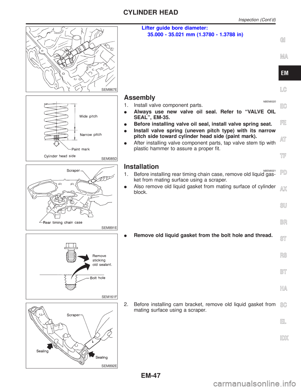
Lifter guide bore diameter:
35.000 - 35.021 mm (1.3780 - 1.3788 in)
SEM085D
AssemblyNBEM00201. Install valve component parts.
IAlways use new valve oil seal. Refer to ªVALVE OIL
SEALº, EM-35.
IBefore installing valve oil seal, install valve spring seat.
IInstall valve spring (uneven pitch type) with its narrow
pitch side toward cylinder head side (paint mark).
IAfter installing valve component parts, tap valve stem tip with
plastic hammer to assure a proper fit.
SEM891E
InstallationNBEM00211. Before installing rear timing chain case, remove old liquid gas-
ket from mating surface using a scraper.
IAlso remove old liquid gasket from mating surface of cylinder
block.
SEM161F
IRemove old liquid gasket from the bolt hole and thread.
SEM892E
2. Before installing cam bracket, remove old liquid gasket from
mating surface using a scraper.
GI
MA
LC
EC
FE
AT
TF
PD
AX
SU
BR
ST
RS
BT
HA
SC
EL
IDX
CYLINDER HEAD
Inspection (Cont'd)
EM-47
Page 1695 of 2395
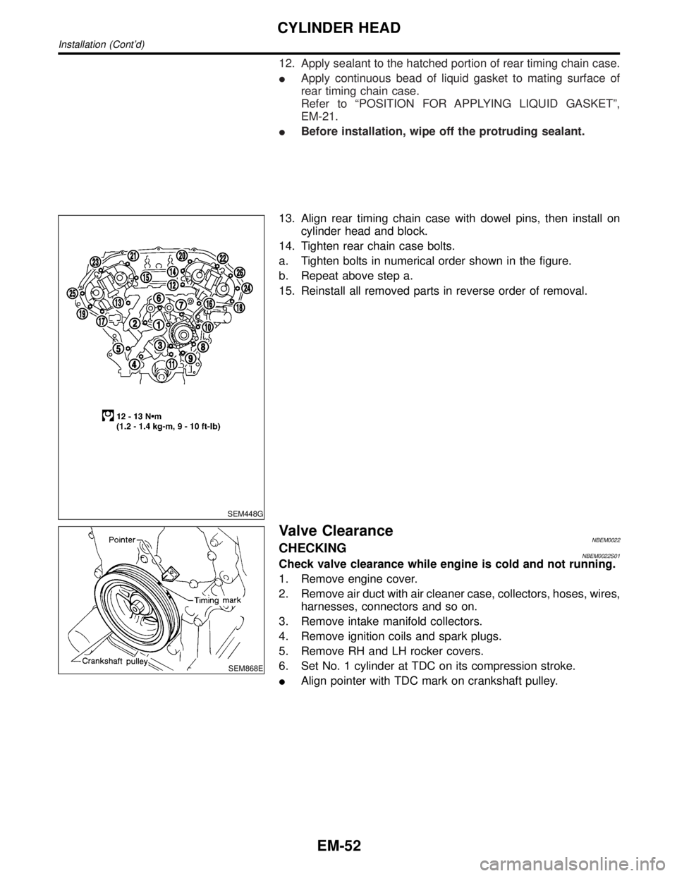
12. Apply sealant to the hatched portion of rear timing chain case.
IApply continuous bead of liquid gasket to mating surface of
rear timing chain case.
Refer to ªPOSITION FOR APPLYING LIQUID GASKETº,
EM-21.
IBefore installation, wipe off the protruding sealant.
SEM448G
13. Align rear timing chain case with dowel pins, then install on
cylinder head and block.
14. Tighten rear chain case bolts.
a. Tighten bolts in numerical order shown in the figure.
b. Repeat above step a.
15. Reinstall all removed parts in reverse order of removal.
SEM868E
Valve ClearanceNBEM0022CHECKINGNBEM0022S01Check valve clearance while engine is cold and not running.
1. Remove engine cover.
2. Remove air duct with air cleaner case, collectors, hoses, wires,
harnesses, connectors and so on.
3. Remove intake manifold collectors.
4. Remove ignition coils and spark plugs.
5. Remove RH and LH rocker covers.
6. Set No. 1 cylinder at TDC on its compression stroke.
IAlign pointer with TDC mark on crankshaft pulley.
CYLINDER HEAD
Installation (Cont'd)
EM-52
Page 1705 of 2395
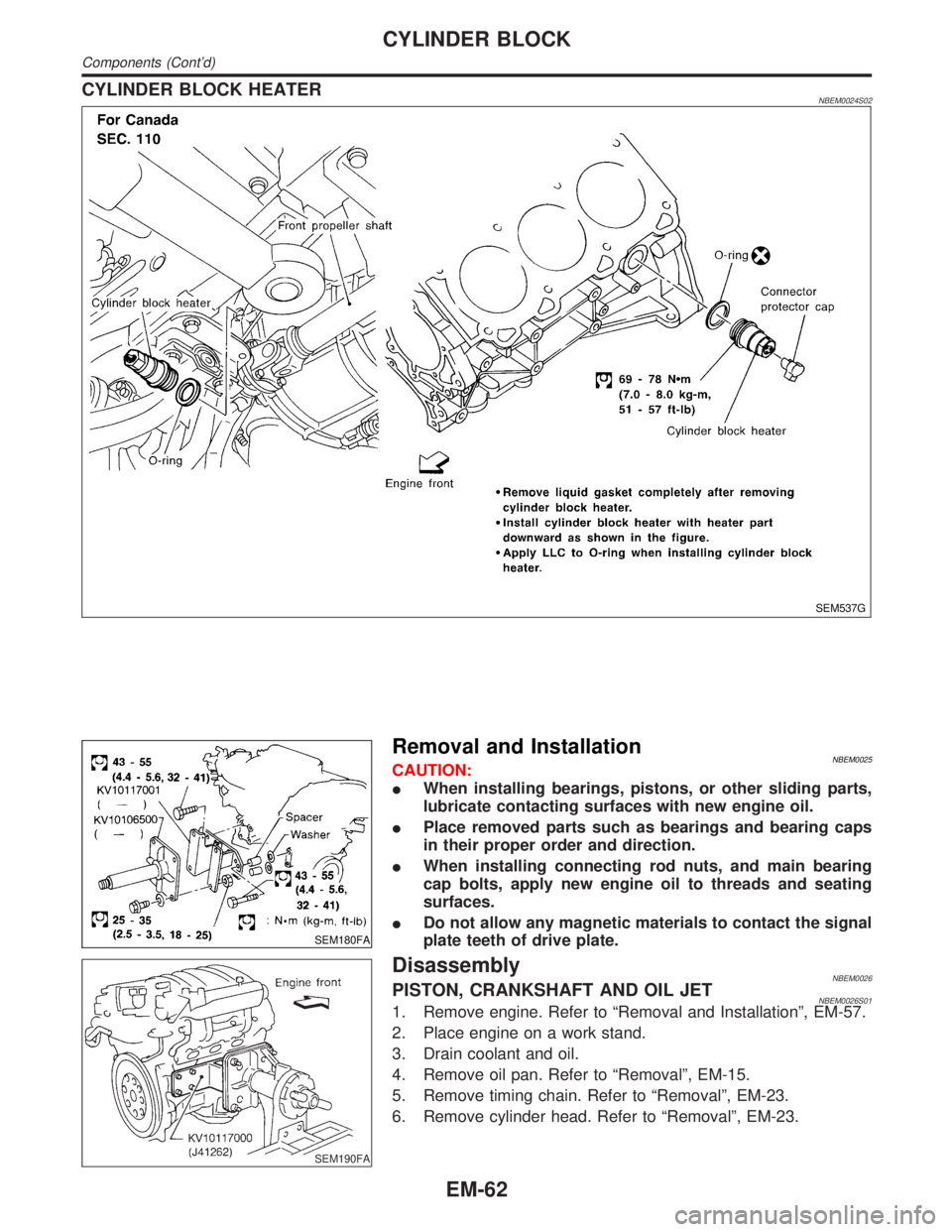
CYLINDER BLOCK HEATERNBEM0024S02
SEM537G
SEM180FA
Removal and InstallationNBEM0025CAUTION:
IWhen installing bearings, pistons, or other sliding parts,
lubricate contacting surfaces with new engine oil.
IPlace removed parts such as bearings and bearing caps
in their proper order and direction.
IWhen installing connecting rod nuts, and main bearing
cap bolts, apply new engine oil to threads and seating
surfaces.
IDo not allow any magnetic materials to contact the signal
plate teeth of drive plate.
SEM190FA
DisassemblyNBEM0026PISTON, CRANKSHAFT AND OIL JETNBEM0026S011. Remove engine. Refer to ªRemoval and Installationº, EM-57.
2. Place engine on a work stand.
3. Drain coolant and oil.
4. Remove oil pan. Refer to ªRemovalº, EM-15.
5. Remove timing chain. Refer to ªRemovalº, EM-23.
6. Remove cylinder head. Refer to ªRemovalº, EM-23.
CYLINDER BLOCK
Components (Cont'd)
EM-62
Page 1724 of 2395
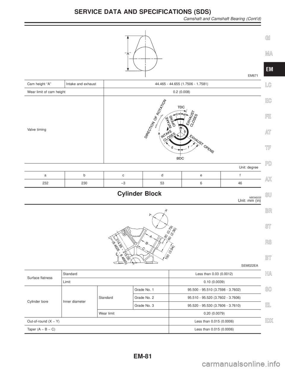
EM671
Cam height ªAº Intake and exhaust 44.465 - 44.655 (1.7506 - 1.7581)
Wear limit of cam height 0.2 (0.008)
Valve timing
Unit: degree
abcde f
232 230 ±3 53 6 46
Cylinder BlockNBEM0035Unit: mm (in)
SEM022EA
Surface flatnessStandardLess than 0.03 (0.0012)
Limit0.10 (0.0039)
Cylinder bore Inner diameterStandardGrade No. 1 95.500 - 95.510 (3.7598 - 3.7602)
Grade No. 2 95.510 - 95.520 (3.7602 - 3.7606)
Grade No. 3 95.520 - 95.530 (3.7606 - 3.7610)
Wear limit 0.20 (0.0079)
Out-of-round (X þ Y)Less than 0.015 (0.0006)
Taper (AþBþC)Less than 0.015 (0.0006)
GI
MA
LC
EC
FE
AT
TF
PD
AX
SU
BR
ST
RS
BT
HA
SC
EL
IDX
SERVICE DATA AND SPECIFICATIONS (SDS)
Camshaft and Camshaft Bearing (Cont'd)
EM-81
Page 1745 of 2395
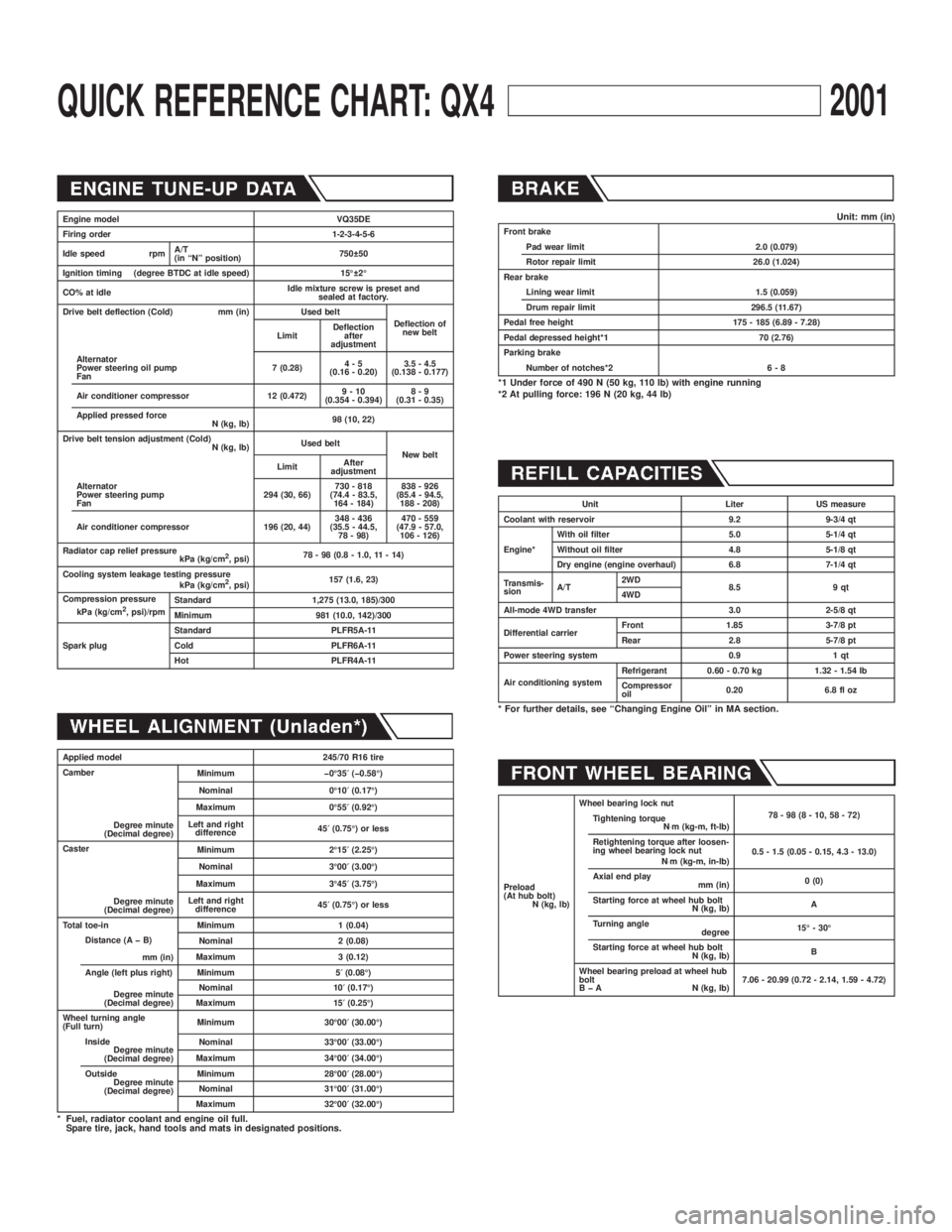
QUICK REFERENCE CHART: QX42001
Engine model VQ35DE
Firing order 1-2-3-4-5-6
Idle speed rpmA/T
(in ªNº position)750 50
Ignition timing (degree BTDC at idle speed) 15É 2É
CO% at idleIdle mixture screw is preset and
sealed at factory.
Drive belt deflection (Cold) mm (in) Used belt
Deflection of
new belt
LimitDeflection
after
adjustment
Alternator
Power steering oil pump
Fan7 (0.28)4-5
(0.16 - 0.20)3.5 - 4.5
(0.138 - 0.177)
Air conditioner compressor 12 (0.472)9-10
(0.354 - 0.394)8-9
(0.31 - 0.35)
Applied pressed force
N (kg, lb)98 (10, 22)
Drive belt tension adjustment (Cold)
N (kg, lb)Used belt
New belt
LimitAfter
adjustment
Alternator
Power steering pump
Fan294 (30, 66)730 - 818
(74.4 - 83.5,
164 - 184)838 - 926
(85.4 - 94.5,
188 - 208)
Air conditioner compressor 196 (20, 44)348 - 436
(35.5 - 44.5,
78 - 98)470 - 559
(47.9 - 57.0,
106 - 126)
Radiator cap relief pressure
kPa (kg/cm
2, psi)78 - 98 (0.8 - 1.0, 11 - 14)
Cooling system leakage testing pressure
kPa (kg/cm
2, psi)157 (1.6, 23)
Compression pressure
kPa (kg/cm
2, psi)/rpmStandard 1,275 (13.0, 185)/300
Minimum 981 (10.0, 142)/300
Spark plugStandard PLFR5A-11
Cold PLFR6A-11
Hot PLFR4A-11
Applied model 245/70 R16 tire
Camber
Degree minute
(Decimal degree)Minimum þ0É35¢(þ0.58É)
Nominal 0É10¢(0.17É)
Maximum 0É55¢(0.92É)
Left and right
difference45¢(0.75É) or less
Caster
Degree minute
(Decimal degree)Minimum 2É15¢(2.25É)
Nominal 3É00¢(3.00É)
Maximum 3É45¢(3.75É)
Left and right
difference45¢(0.75É) or less
Total toe-in Minimum 1 (0.04)
Distance (A þ B)
mm (in)Nominal 2 (0.08)
Maximum 3 (0.12)
Angle (left plus right)
Degree minute
(Decimal degree)Minimum 5¢(0.08É)
Nominal 10¢(0.17É)
Maximum 15¢(0.25É)
Wheel turning angle
(Full turn)Minimum 30É00¢(30.00É)
Inside
Degree minute
(Decimal degree)Nominal 33É00¢(33.00É)
Maximum 34É00¢(34.00É)
Outside
Degree minute
(Decimal degree)Minimum 28É00¢(28.00É)
Nominal 31É00¢(31.00É)
Maximum 32É00¢(32.00É)
* Fuel, radiator coolant and engine oil full.
Spare tire, jack, hand tools and mats in designated positions.
Unit: mm (in)Front brake
Pad wear limit 2.0 (0.079)
Rotor repair limit 26.0 (1.024)
Rear brake
Lining wear limit 1.5 (0.059)
Drum repair limit 296.5 (11.67)
Pedal free height 175 - 185 (6.89 - 7.28)
Pedal depressed height*1 70 (2.76)
Parking brake
Number of notches*2 6 - 8
*1 Under force of 490 N (50 kg, 110 lb) with engine running
*2 At pulling force: 196 N (20 kg, 44 lb)
Unit Liter US measure
Coolant with reservoir 9.2 9-3/4 qt
Engine*With oil filter 5.0 5-1/4 qt
Without oil filter 4.8 5-1/8 qt
Dry engine (engine overhaul) 6.8 7-1/4 qt
Transmis-
sionA/T2WD
8.5 9 qt
4WD
All-mode 4WD transfer 3.0 2-5/8 qt
Differential carrierFront 1.85 3-7/8 pt
Rear 2.8 5-7/8 pt
Power steering system 0.9 1 qt
Air conditioning systemRefrigerant 0.60 - 0.70 kg 1.32 - 1.54 lb
Compressor
oil0.20 6.8 fl oz
* For further details, see ªChanging Engine Oilº in MA section.
Preload
(At hub bolt)
N (kg, lb)Wheel bearing lock nut
78-98(8-10,58-72)
Tightening torque
N×m (kg-m, ft-lb)
Retightening torque after loosen-
ing wheel bearing lock nut
N×m (kg-m, in-lb)0.5 - 1.5 (0.05 - 0.15, 4.3 - 13.0)
Axial end play
mm (in)0 (0)
Starting force at wheel hub bolt
N (kg, lb)A
Turning angle
degree15É - 30É
Starting force at wheel hub bolt
N (kg, lb)B
Wheel bearing preload at wheel hub
bolt
B þ A N (kg, lb)7.06 - 20.99 (0.72 - 2.14, 1.59 - 4.72)
Page 1796 of 2395
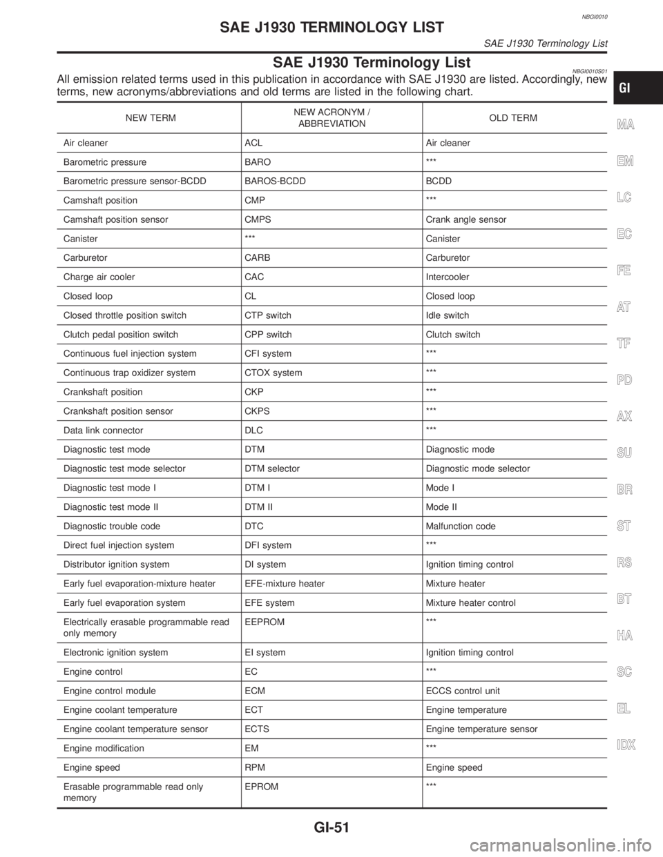
NBGI0010
SAE J1930 Terminology ListNBGI0010S01All emission related terms used in this publication in accordance with SAE J1930 are listed. Accordingly, new
terms, new acronyms/abbreviations and old terms are listed in the following chart.
NEW TERMNEW ACRONYM /
ABBREVIATIONOLD TERM
Air cleaner ACL Air cleaner
Barometric pressure BARO ***
Barometric pressure sensor-BCDD BAROS-BCDD BCDD
Camshaft position CMP ***
Camshaft position sensor CMPS Crank angle sensor
Canister *** Canister
Carburetor CARB Carburetor
Charge air cooler CAC Intercooler
Closed loop CL Closed loop
Closed throttle position switch CTP switch Idle switch
Clutch pedal position switch CPP switch Clutch switch
Continuous fuel injection system CFI system ***
Continuous trap oxidizer system CTOX system ***
Crankshaft position CKP ***
Crankshaft position sensor CKPS ***
Data link connector DLC ***
Diagnostic test mode DTM Diagnostic mode
Diagnostic test mode selector DTM selector Diagnostic mode selector
Diagnostic test mode I DTM I Mode I
Diagnostic test mode II DTM II Mode II
Diagnostic trouble code DTC Malfunction code
Direct fuel injection system DFI system ***
Distributor ignition system DI system Ignition timing control
Early fuel evaporation-mixture heater EFE-mixture heater Mixture heater
Early fuel evaporation system EFE system Mixture heater control
Electrically erasable programmable read
only memoryEEPROM ***
Electronic ignition system EI system Ignition timing control
Engine control EC ***
Engine control module ECM ECCS control unit
Engine coolant temperature ECT Engine temperature
Engine coolant temperature sensor ECTS Engine temperature sensor
Engine modification EM ***
Engine speed RPM Engine speed
Erasable programmable read only
memoryEPROM ***MA
EM
LC
EC
FE
AT
TF
PD
AX
SU
BR
ST
RS
BT
HA
SC
EL
IDX
SAE J1930 TERMINOLOGY LIST
SAE J1930 Terminology List
GI-51