INSTALLATION INFINITI QX4 2001 Factory Service Manual
[x] Cancel search | Manufacturer: INFINITI, Model Year: 2001, Model line: QX4, Model: INFINITI QX4 2001Pages: 2395, PDF Size: 43.2 MB
Page 1531 of 2395

DIAGNOSTIC PROCEDURE 7=NBEL0224S11Self-diagnostic results:
ªLOCK MODEº displayed on CONSULT-II screen
1 CONFIRM SELF-DIAGNOSTIC RESULTS
Confirm SELF-DIAGNOSTIC RESULTS ªLOCK MODEº is displayed on CONSULT-II screen.
SEL371X
Is CONSULT-II screen displayed as above?
Ye s©GO TO 2.
No©GO TO SYMPTOM MATRIX CHART 1.
2 ESCAPE FROM LOCK MODE
1. Turn ignition switch OFF.
2. Turn ignition switch ON with registered key. (Do not start engine.) Wait 5 seconds.
3. Return the key to OFF position.
4. Repeat steps 2 and 3 twice (total of three cycles).
5. Start the engine.
Does engine start?
Ye s©System is OK.
(Now system is escaped from ªLOCK MODEº.)
No©GO TO 3.
3 CHECK IMMU ILLUSTRATION
Check IMMU installation. Refer to ªHow to Replace IMMUº in EL-347.
OK or NG
OK©GO TO 4.
NG©Reinstall IMMU correctly.
IVIS (INFINITI VEHICLE IMMOBILIZER SYSTEM Ð NATS)
Trouble Diagnoses (Cont'd)
EL-346
Page 1644 of 2395

ENGINE MECHANICAL
SECTION
EM
CONTENTS
PRECAUTIONS...............................................................3
Parts Requiring Angular Tightening .............................3
Liquid Gasket Application Procedure ..........................3
PREPARATION...............................................................4
Special Service Tools ..................................................4
Commercial Service Tools ...........................................6
NOISE, VIBRATION AND HARSHNESS (NVH)
TROUBLESHOOTING.....................................................8
NVH Troubleshooting - Engine Noise .........................9
OUTER COMPONENT PARTS.....................................10
Removal and Installation ...........................................10
TIGHTENING PROCEDURES...................................12
MEASUREMENT OF COMPRESSION PRESSURE....14
OIL PAN.........................................................................15
Components...............................................................15
Removal .....................................................................15
Installation ..................................................................18
TIMING CHAIN..............................................................20
Components...............................................................20
POSITION FOR APPLYING LIQUID GASKET............21
Removal .....................................................................23
Inspection...................................................................29
Installation ..................................................................29
OIL SEAL.......................................................................35
Replacement ..............................................................35
VALVE OIL SEAL.....................................................35
OIL SEAL INSTALLATION DIRECTION.....................36
FRONT OIL SEAL....................................................36
REAR OIL SEAL......................................................36
CYLINDER HEAD..........................................................38
Components...............................................................38
Removal .....................................................................39
Disassembly...............................................................41
Inspection...................................................................42
CYLINDER HEAD DISTORTION...............................42
CAMSHAFT VISUAL CHECK....................................42
CAMSHAFT RUNOUT..............................................42
CAMSHAFT CAM HEIGHT.......................................42
CAMSHAFT JOURNAL CLEARANCE........................42
CAMSHAFT END PLAY............................................43
CAMSHAFT SPROCKET RUNOUT...........................43
VALVE GUIDE CLEARANCE....................................43
VALVE GUIDE REPLACEMENT................................44
VALVE SEATS.........................................................45
REPLACING VALVE SEAT FOR SERVICE PARTS....45
VALVE DIMENSIONS...............................................46
VALVE SPRING.......................................................46
VALVE LIFTER........................................................46
Assembly ...................................................................47
Installation ..................................................................47
Valve Clearance.........................................................52
CHECKING.............................................................52
ADJUSTING............................................................54
ENGINE ASSEMBLY.....................................................57
Removal and Installation ...........................................57
REMOVAL...............................................................58
INSTALLATION........................................................60
CYLINDER BLOCK.......................................................61
Components...............................................................61
CYLINDER BLOCK HEATER....................................62
Removal and Installation ...........................................62
Disassembly...............................................................62
PISTON, CRANKSHAFT AND OIL JET......................62
Inspection...................................................................63
PISTON AND PISTON PIN CLEARANCE..................63
PISTON RING SIDE CLEARANCE............................64
PISTON RING END GAP..........................................64
CONNECTING ROD BEND AND TORSION...............65
CYLINDER BLOCK DISTORTION AND WEAR...........65
PISTON-TO-BORE CLEARANCE..............................66
CRANKSHAFT.........................................................67
BEARING CLEARANCE...........................................67
CONNECTING ROD BUSHING CLEARANCE
(SMALL END)
..........................................................70
DRIVE PLATE RUNOUT..........................................70
Assembly ...................................................................71
PISTON..................................................................71
OIL JET..................................................................71
CRANKSHAFT.........................................................71
REPLACEMENT OF PILOT CONVERTER.................74
DRIVE PLATE.........................................................74
GI
MA
LC
EC
FE
AT
TF
PD
AX
SU
BR
ST
RS
BT
HA
SC
EL
IDX
Page 1653 of 2395

Removal and InstallationNBEM0006
SEM483G
1. Intake manifold collector support
2. Lower intake manifold collector
3. Fuel damper and fuel feed hose
assembly
4. Injector
5. Fuel tube assembly6. Fuel pressure regulator
7. Ignition coil with power transistor
8. Upper intake manifold collector
9. Intake manifold
10. Throttle body11. IACV-AAC valve
12. EVAP canister purge volume con-
trol solenoid valve
13. Swirl control valve
14. Variable induction air control valve
control actuator
OUTER COMPONENT PARTS
Removal and Installation
EM-10
Page 1654 of 2395

SEM484GA
1. Heated oxygen sensor 1 (front)
(bank 1)
2. Heated oxygen sensor 1 (front)
(bank 2)
3. TWC (manifold)4. Thermostat with water inlet
5. Exhaust manifold
6. Thermal transmitter
7. Engine coolant temperature8. Water control valve
9. Water outlet housing
10. Cylinder block water outlet
GI
MA
LC
EC
FE
AT
TF
PD
AX
SU
BR
ST
RS
BT
HA
SC
EL
IDX
OUTER COMPONENT PARTS
Removal and Installation (Cont'd)
EM-11
Page 1655 of 2395

SEM950F
TIGHTENING PROCEDURESNBEM0006S01Intake ManifoldNBEM0006S0101ITighten in numerical order shown in the figure.
1. Tighten all bolts and nuts to 5 to 10 N´m (0.5 to 1.0 kg-m, 44
to 86 in-lb).
2. Finally tighten all bolts and nuts to 26 to 31 N´m (2.7 to 3.2
kg-m, 20 to 23 ft-lb).
ITighten all bolts and nuts to the final torque, evenly dividing the
tightening into at least five steps.
SEM473G
Fuel TubeNBEM0006S0102ITighten in numerical order shown in the figure.
1. Tighten all bolts to 9.3 to 10.8 N´m (0.95 to 1.1 kg-m, 83 to 95
in-lb).
2. Then tighten all bolts to 21 to 26 N´m (2.1 to 2.7 kg-m, 15 to
20 ft-lb).
SEM474G
Fuel Pressure RegulatorNBEM0006S0103Tighten fuel pressure regulator to 2.9 to 3.8 N´m (0.3 to 0.39 kg-m,
26.0 to 33.9 in-lb).
ITighten screws evenly several times to have the fuel pres-
sure regulator tightened at the specified torque.
IAlways replace O-ring with new ones.
ILubricate O-ring with new engine oil.
SEM475G
Throttle BodyNBEM0006S0105ITighten in numerical order shown in the figure.
1. Tighten all bolts to 8.8 to 10.8 N´m (0.9 to 1.1 kg-m, 79 to 95
in-lb).
2. Then tighten all bolts to 18 to 21 N´m (1.8 to 2.2 kg-m, 13 to
15 ft-lb).
SEM476G
Upper Intake Manifold CollectorNBEM0006S0107Tighten bolts and nuts to 18 to 21 N´m (1.8 to 2.2 kg-m, 13 to 15
ft-lb) in numerical order shown in the figure.
OUTER COMPONENT PARTS
Removal and Installation (Cont'd)
EM-12
Page 1656 of 2395

SEM477G
Lower Intake Manifold CollectorNBEM0006S0108Tighten bolts and nuts to 18 to 21 N´m (1.8 to 2.2 kg-m, 13 to 15
ft-lb) in numerical order shown in the figure.
SEM478G
SEM479G
Exhaust ManifoldNBEM0006S0109Tighten nuts to 28 to 32 N´m (2.9 to 3.3 kg-m, 21 to 24 ft-lb) in
numerical order shown in the figure.
SEM607G
TWC (Manifold)NBEM0006S0110IAlign the mating mark as shown for locating exhaust flange.
SEM609G
IInstall washer and mesh washer as shown.
GI
MA
LC
EC
FE
AT
TF
PD
AX
SU
BR
ST
RS
BT
HA
SC
EL
IDX
OUTER COMPONENT PARTS
Removal and Installation (Cont'd)
EM-13
Page 1659 of 2395

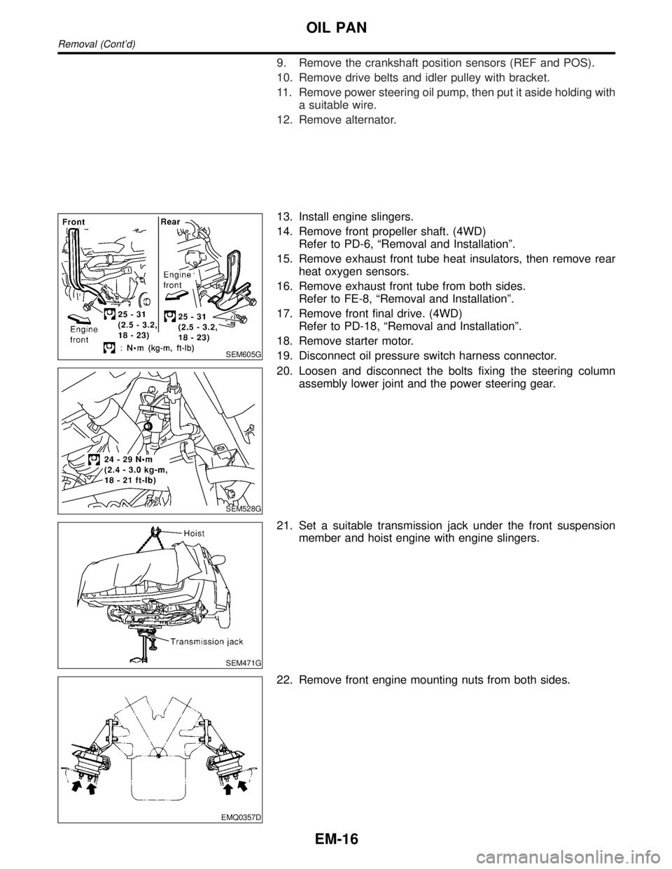
9. Remove the crankshaft position sensors (REF and POS).
10. Remove drive belts and idler pulley with bracket.
11. Remove power steering oil pump, then put it aside holding with
a suitable wire.
12. Remove alternator.
SEM605G
13. Install engine slingers.
14. Remove front propeller shaft. (4WD)
Refer to PD-6, ªRemoval and Installationº.
15. Remove exhaust front tube heat insulators, then remove rear
heat oxygen sensors.
16. Remove exhaust front tube from both sides.
Refer to FE-8, ªRemoval and Installationº.
17. Remove front final drive. (4WD)
Refer to PD-18, ªRemoval and Installationº.
18. Remove starter motor.
19. Disconnect oil pressure switch harness connector.
SEM528G
20. Loosen and disconnect the bolts fixing the steering column
assembly lower joint and the power steering gear.
SEM471G
21. Set a suitable transmission jack under the front suspension
member and hoist engine with engine slingers.
EMQ0357D
22. Remove front engine mounting nuts from both sides.
OIL PAN
Removal (Cont'd)
EM-16
Page 1661 of 2395

SEM464G
30. Remove O-rings from cylinder block and oil pump body.
SEM465G
31. Remove front cover gasket and rear oil seal retainer gasket.
SEM466G
InstallationNBEM00101. Before installing oil pan, remove old liquid gasket from mating
surface using a scraper.
IAlso remove old liquid gasket from mating surface of cyl-
inder block.
IRemove old liquid gasket from the bolt hole and thread.
SEM964E
2. Apply sealant to front cover gasket and rear oil seal retainer
gasket.
SEM465G
3. Install front cover gasket and rear oil seal retainer gasket.
OIL PAN
Removal (Cont'd)
EM-18
Page 1662 of 2395

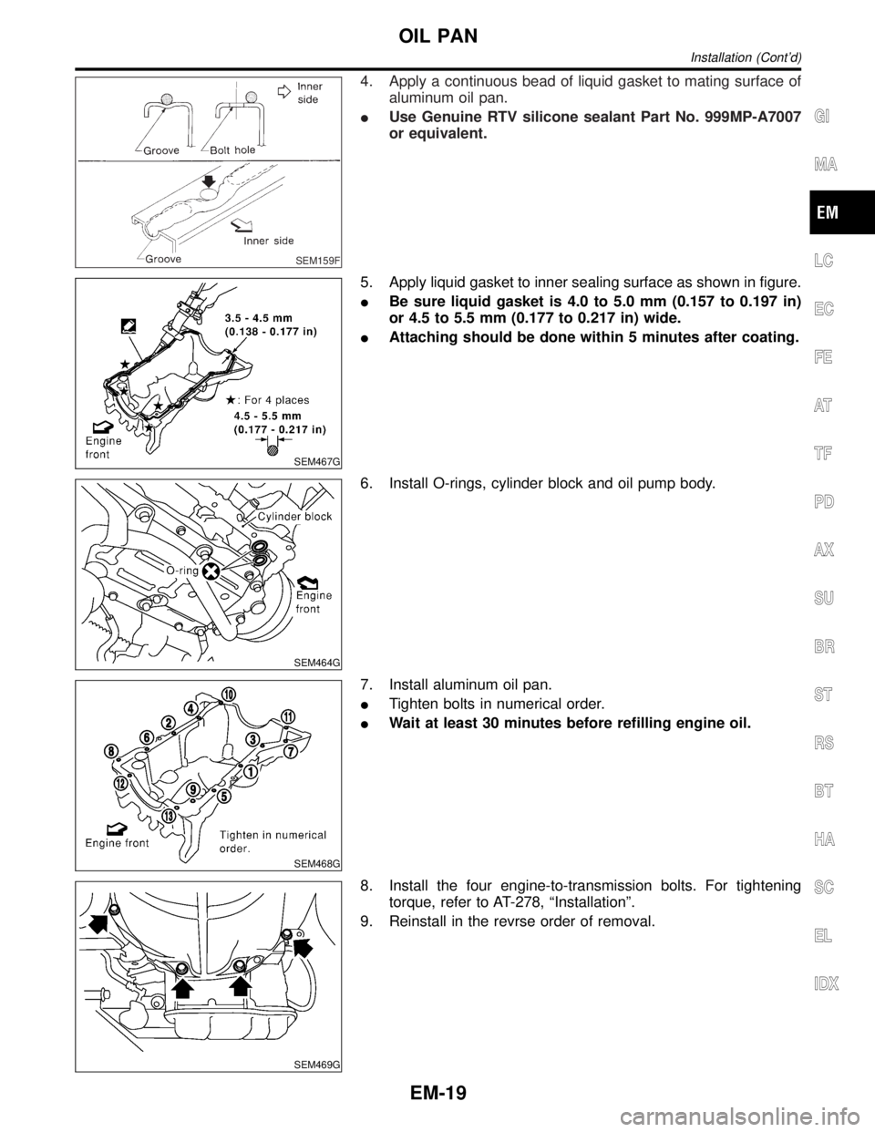
SEM159F
4. Apply a continuous bead of liquid gasket to mating surface of
aluminum oil pan.
IUse Genuine RTV silicone sealant Part No. 999MP-A7007
or equivalent.
SEM467G
5. Apply liquid gasket to inner sealing surface as shown in figure.
IBe sure liquid gasket is 4.0 to 5.0 mm (0.157 to 0.197 in)
or 4.5 to 5.5 mm (0.177 to 0.217 in) wide.
IAttaching should be done within 5 minutes after coating.
SEM464G
6. Install O-rings, cylinder block and oil pump body.
SEM468G
7. Install aluminum oil pan.
ITighten bolts in numerical order.
IWait at least 30 minutes before refilling engine oil.
SEM469G
8. Install the four engine-to-transmission bolts. For tightening
torque, refer to AT-278, ªInstallationº.
9. Reinstall in the revrse order of removal.
GI
MA
LC
EC
FE
AT
TF
PD
AX
SU
BR
ST
RS
BT
HA
SC
EL
IDX
OIL PAN
Installation (Cont'd)
EM-19
Page 1664 of 2395

POSITION FOR APPLYING LIQUID GASKET=NBEM0011S01Refer to ªInstallationº in ªOIL PANº, EM-18.
IBefore installation, wipe off the protruding sealant.
GI
MA
LC
EC
FE
AT
TF
PD
AX
SU
BR
ST
RS
BT
HA
SC
EL
IDX
TIMING CHAIN
Components (Cont'd)
EM-21