INSTALLATION INFINITI QX4 2001 Factory Service Manual
[x] Cancel search | Manufacturer: INFINITI, Model Year: 2001, Model line: QX4, Model: INFINITI QX4 2001Pages: 2395, PDF Size: 43.2 MB
Page 1701 of 2395
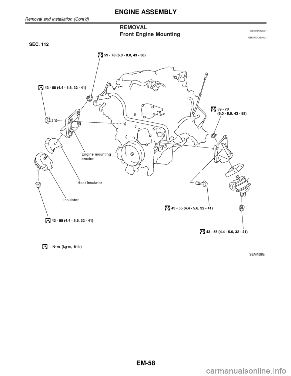
REMOVALNBEM0042S01Front Engine MountingNBEM0042S0101
SEM458G
ENGINE ASSEMBLY
Removal and Installation (Cont'd)
EM-58
Page 1702 of 2395
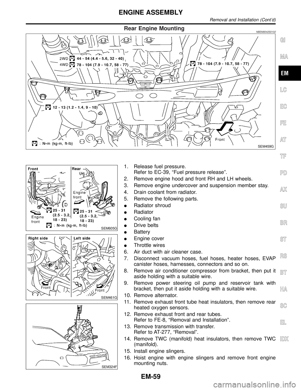
Rear Engine MountingNBEM0042S0102
SEM459G
SEM605G
SEM461G
SEM324F
1. Release fuel pressure.
Refer to EC-39, ªFuel pressure releaseº.
2. Remove engine hood and front RH and LH wheels.
3. Remove engine undercover and suspension member stay.
4. Drain coolant from radiator.
5. Remove the following parts.
IRadiator shroud
IRadiator
ICooling fan
IDrive belts
IBattery
IEngine cover
IThrottle wires
6. Air duct with air cleaner case.
7. Disconnect vacuum hoses, fuel hoses, heater hoses, EVAP
canister hoses, harnesses, connectors and so on.
8. Remove air conditioner compressor from bracket, then put it
aside holding with a suitable wire.
9. Remove power steering oil pump and reservoir tank with
bracket, then put it aside holding with a suitable wire.
10. Remove alternator.
11. Remove exhaust front tube heat insulators, then remove rear
heated oxygen sensors.
12. Remove exhaust front and rear tubes.
Refer to FE-8, ªRemoval and Installationº.
13. Remove transmission with transfer.
Refer to AT-277, ªRemovalº.
14. Remove TWC (manifold) heat insulators, then remove TWC
(manifold).
15. Install engine slingers.
16. Hoist engine with engine slingers and remove front engine
mounting nuts.
GI
MA
LC
EC
FE
AT
TF
PD
AX
SU
BR
ST
RS
BT
HA
SC
EL
IDX
ENGINE ASSEMBLY
Removal and Installation (Cont'd)
EM-59
Page 1703 of 2395
17. Remove engine from vehicle.
INSTALLATIONNBEM0042S02Installation is in the reverse order of removal.
ENGINE ASSEMBLY
Removal and Installation (Cont'd)
EM-60
Page 1705 of 2395
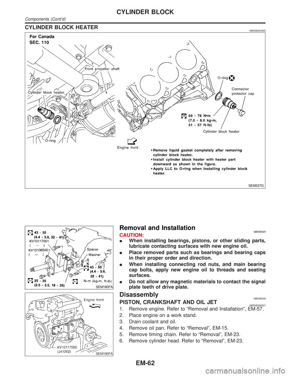
CYLINDER BLOCK HEATERNBEM0024S02
SEM537G
SEM180FA
Removal and InstallationNBEM0025CAUTION:
IWhen installing bearings, pistons, or other sliding parts,
lubricate contacting surfaces with new engine oil.
IPlace removed parts such as bearings and bearing caps
in their proper order and direction.
IWhen installing connecting rod nuts, and main bearing
cap bolts, apply new engine oil to threads and seating
surfaces.
IDo not allow any magnetic materials to contact the signal
plate teeth of drive plate.
SEM190FA
DisassemblyNBEM0026PISTON, CRANKSHAFT AND OIL JETNBEM0026S011. Remove engine. Refer to ªRemoval and Installationº, EM-57.
2. Place engine on a work stand.
3. Drain coolant and oil.
4. Remove oil pan. Refer to ªRemovalº, EM-15.
5. Remove timing chain. Refer to ªRemovalº, EM-23.
6. Remove cylinder head. Refer to ªRemovalº, EM-23.
CYLINDER BLOCK
Components (Cont'd)
EM-62
Page 1717 of 2395

SEM954E
7. Measure connecting rod side clearance.
Connecting rod side clearance:
Standard
0.20 - 0.35 mm (0.0079 - 0.0138 in)
Limit
0.40 mm (0.0157 in)
If beyond the limit, replace connecting rod and/or crankshaft.
8. Install rear oil seal retainer.
SEM005G
REPLACEMENT OF PILOT CONVERTERNBEM0028S041. Remove pilot converter using tool or suitable tool.
SEM537E
2. Install pilot converter as shown.
SEM539G
DRIVE PLATENBEM0028S06Install drive plate.
IInstall the drive plate and reinforce plate in the direction shown
in the figure.
ISecure the crankshaft using a ring gear stopper.
ITighten the installation bolts crosswise over several times.
CYLINDER BLOCK
Assembly (Cont'd)
EM-74
Page 1730 of 2395

ACCELERATOR CONTROL, FUEL &
EXHAUST SYSTEMS
SECTION
FE
CONTENTS
PREPARATION...............................................................2
Special Service Tool ....................................................2
Commercial Service Tools ...........................................2
ACCELERATOR CONTROL SYSTEM...........................3
Removal and Installation .............................................3
Adjusting Accelerator Wire ..........................................3FUEL SYSTEM................................................................4
Removal and Installation .............................................4
FUEL TANK...............................................................5
FUEL PUMP AND GAUGE.........................................6
EXHAUST SYSTEM........................................................8
Removal and Installation .............................................8
GI
MA
EM
LC
EC
AT
TF
PD
AX
SU
BR
ST
RS
BT
HA
SC
EL
IDX
Page 1732 of 2395

Removal and InstallationNBFE0002CAUTION:
IWhen removing accelerator wire, make a mark to indicate lock nut's initial position.
ICheck that throttle valve opens fully when accelerator pedal is fully depressed. Also check that it
returns to idle position when pedal is released.
ICheck accelerator control parts for improper contact with any adjacent parts.
IWhen connecting accelerator wire, be careful not to twist or scratch its inner wire.
IRefer to EL-240, ªAUTOMATIC SPEED CONTROL DEVICEº for ASCD wire adjustment.
SFE635A
SEF793W
SFE249AE
Adjusting Accelerator WireNBFE00031. Remove the vacuum hose connected to the throttle opener.
2. Connect suitable vacuum hose to vacuum pump as shown left.
3. Apply vacuum [more than þ40.0 kPa (þ300 mmHg, þ11.81
inHg)] until the throttle drum becomes free from the rod of the
throttle opener.
Make sure that there is clearance between the throttle
drum and rod.
If NG, refer to EC-101, ªBasic Inspectionº.
If OK, go to following step.
4. Loosen lock nut.
5. Tighten accelerator adjusting nut until throttle drum starts to
move.
6. From that position, turn back adjusting nut 1.5 to 2 turns, and
secure lock nut.
7. Release vacuum from the throttle opener.
8. Remove vacuum pump and vacuum hose from the throttle
opener.
9. Reinstall the original vacuum hose to the throttle opener
securely.
GI
MA
EM
LC
EC
AT
TF
PD
AX
SU
BR
ST
RS
BT
HA
SC
EL
IDX
ACCELERATOR CONTROL SYSTEM
Removal and Installation
FE-3
Page 1733 of 2395
Removal and InstallationNBFE0004WARNING:
When replacing fuel line parts, be sure to observe the follow-
ing:
IPut a ªCAUTION: INFLAMMABLEº sign in workshop.
IDo not smoke while servicing fuel system. Keep open
flames and sparks away from work area.
IBe sure to furnish the workshop with a CO
2fire extin-
guisher.
CAUTION:
IBefore removing fuel line parts, carry out the following
procedures:
a) Put drained fuel in an explosion-proof container and put
lid on securely.
b) Release fuel pressure from fuel line. Refer to MA-16,
ªChanging Fuel Filterº.
c) Disconnect battery ground cable.
IAlways replace O-ring with new ones.
IDo not kink or twist hose and tube when they are installed.
IDo not tighten hose clamps excessively to avoid damag-
ing hoses.
IWhen installing fuel check valve, be careful of its desig-
nated direction. Refer to EC-32, ªEVAPORATIVE EMIS-
SION SYSTEMº.
IAfter installation, run engine and check for fuel leaks at
connections.
FUEL SYSTEM
Removal and Installation
FE-4
Page 1734 of 2395

SFE419AA
SFE420A
FUEL TANKNBFE0004S011. Release fuel pressure from fuel line.
Refer to MA-16, ªChanging Fuel Filterº.
2. Remove inspection hole cover located behind the rear seat.
3. Disconnect harness connectors under inspection hole cover.
4. Disconnect fuel hoses.
IPut mating marks on hoses for correct installation.
SFE468A
5. Disconnect filler hose, vent hose and evaporation hose at fuel
tank side.
GI
MA
EM
LC
EC
AT
TF
PD
AX
SU
BR
ST
RS
BT
HA
SC
EL
IDX
FUEL SYSTEM
Removal and Installation (Cont'd)
FE-5
Page 1735 of 2395

SFE422A
6. Remove parking brake wire from fuel tank protector.
7. Remove fuel tank protector.
SFE469A
8. Remove fuel tank band mounting bolts while supporting fuel
tank.
9. Remove fuel tank.
Installation procedure is the reverse order of removal.
FUEL PUMP AND GAUGENBFE0004S02
SFE541A
1. Release fuel pressure from fuel line.
Refer to MA-16, ªChanging Fuel Filterº.
2. Remove inspection hole cover located behind the rear seat.
3. Disconnect harness connectors and fuel tubes from upper
plate of fuel gauge.
IPut mating marks on tubes for correct installation.
4. Remove fuel gauge retainer and fuel gauge.
FUEL SYSTEM
Removal and Installation (Cont'd)
FE-6