02 sensor INFINITI QX4 2001 Factory Service Manual
[x] Cancel search | Manufacturer: INFINITI, Model Year: 2001, Model line: QX4, Model: INFINITI QX4 2001Pages: 2395, PDF Size: 43.2 MB
Page 447 of 2395

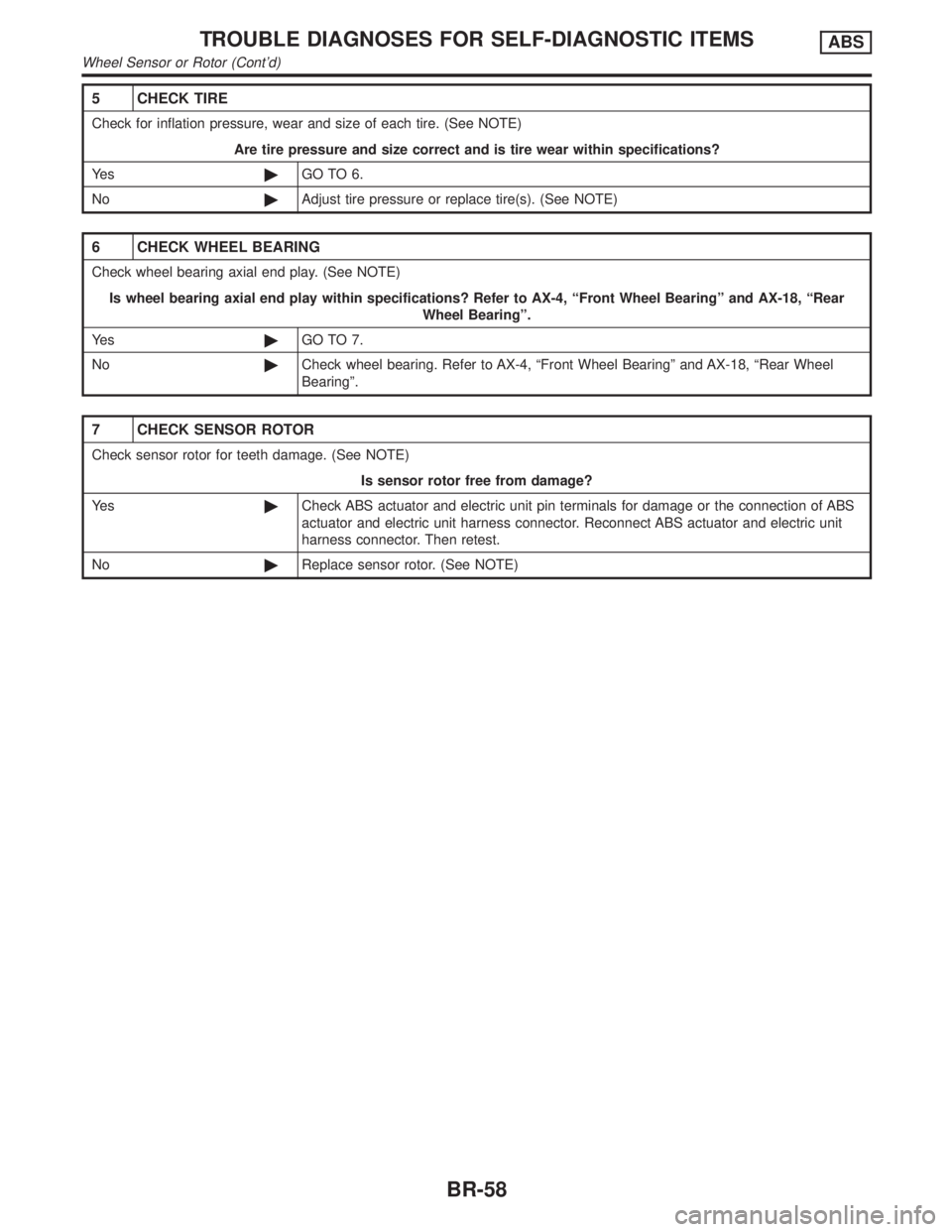
5 CHECK TIRE
Check for inflation pressure, wear and size of each tire. (See NOTE)
Are tire pressure and size correct and is tire wear within specifications?
Ye s©GO TO 6.
No©Adjust tire pressure or replace tire(s). (See NOTE)
6 CHECK WHEEL BEARING
Check wheel bearing axial end play. (See NOTE)
Is wheel bearing axial end play within specifications? Refer to AX-4, ªFront Wheel Bearingº and AX-18, ªRear
Wheel Bearingº.
Ye s©GO TO 7.
No©Check wheel bearing. Refer to AX-4, ªFront Wheel Bearingº and AX-18, ªRear Wheel
Bearingº.
7 CHECK SENSOR ROTOR
Check sensor rotor for teeth damage. (See NOTE)
Is sensor rotor free from damage?
Ye s©Check ABS actuator and electric unit pin terminals for damage or the connection of ABS
actuator and electric unit harness connector. Reconnect ABS actuator and electric unit
harness connector. Then retest.
No©Replace sensor rotor. (See NOTE)
TROUBLE DIAGNOSES FOR SELF-DIAGNOSTIC ITEMSABS
Wheel Sensor or Rotor (Cont'd)
BR-58
Page 454 of 2395

G Sensor and Circuit
DIAGNOSTIC PROCEDURENBBR0114Malfunction code No. 17
1 INSPECTION START
G sensor inspection
SBR504E
©GO TO 2.
2 CHECK FUSE
Check 7.5A fuse No. 7 for ABS actuator and electric unit. For fuse layout, refer to EL-16, ªPOWER SUPPLY ROUTINGº.
Is fuse OK?
Ye s©GO TO 3.
No©Replace fuse.
3 CHECK CONNECTOR
1. Disconnect connectors from ABS actuator and electric unit and G sensor. Check terminals for damage or loose connec-
tion. Then reconnect connectors.
2. Carry out self-diagnosis again.
Does warning lamp activate again?
Ye s©GO TO 4.
No©INSPECTION END
4 CHECK G SENSOR
Refer to ªG SENSORº in ªElectrical Components Inspectionº, BR-67.
Is resistance within specifications?
Ye s©GO TO 5.
No©Replace G sensor.
GI
MA
EM
LC
EC
FE
AT
TF
PD
AX
SU
ST
RS
BT
HA
SC
EL
IDX
TROUBLE DIAGNOSES FOR SELF-DIAGNOSTIC ITEMSABS
G Sensor and Circuit
BR-65
Page 455 of 2395

5 CHECK G SENSOR POWER SUPPLY CIRCUIT
Check voltage between G sensor connector terminals 1, 2 and ground.
SBR861D
Does battery voltage exist?
Ye s©GO TO 6.
No©Check the following. If NG, repair harness or connectors.
IHarness connectors B58, B81
IHarness for open or short between G sensor and fuse
6 CHECK CIRCUIT
1. Disconnect harness connector from ABS actuator and electric unit.
2. Check continuity between ABS actuator and electric unit connector terminals 20, 10 and G sensor connector terminals
17, 51.
SBR505E
Does continuity exist?
Ye s©Check actuator and electric unit pin terminals for damage or the connection of actuator
and electric unit harness connector. Reconnect actuator and electric unit harness con-
nector. Then retest.
No©Check the following. If NG, repair harness or connectors.
IHarness connectors E111, B58, B81
IHarness for open or short between G sensor connector and actuator and electric unit
TROUBLE DIAGNOSES FOR SELF-DIAGNOSTIC ITEMSABS
G Sensor and Circuit (Cont'd)
BR-66
Page 456 of 2395

SBR844DF
ELECTRICAL COMPONENT INSPECTION=NBBR0115G Sensor (4WD models only)NBBR0115S01CAUTION:
The G sensor is easily damaged if it sustains an impact. Be
careful not to drop or bump it.
1. Measure resistance between terminals 2 and 51 of G sensor
unit connector.
G sensor conditionResistance between ter-
minals 2 and 51G sensor switch condi-
tion
Installed in vehicle 1.4 - 1.6 kWªONº
Tilted as shown in figure 4.7 - 5.5 kWªOFFº
2. Measure resistance between terminals 1 and 17 of the G sen-
sor unit connector.
Resistance: 70 - 124W
GI
MA
EM
LC
EC
FE
AT
TF
PD
AX
SU
ST
RS
BT
HA
SC
EL
IDX
TROUBLE DIAGNOSES FOR SELF-DIAGNOSTIC ITEMSABS
G Sensor and Circuit (Cont'd)
BR-67
Page 458 of 2395

1. ABS Works FrequentlyNBBR0107
1 CHECK BRAKE FLUID PRESSURE
Check brake fluid pressure distribution.
Refer to ªInspectionº, ªLOAD SENSING VALVEº, BR-12.
Is brake fluid pressure distribution normal?
Ye s©GO TO 2.
No©Repair. Then perform Preliminary Check.
Refer to BR-50.
2 CHECK WHEEL SENSOR
1. Check wheel sensor connector for terminal damage or loose connections.
2. Perform wheel sensor mechanical check.
Refer to ª7. CHECK SENSOR ROTORº in ªDIAGNOSTIC PROCEDUREº, ªWheel Sensor or Rotorº, BR-56.
Is wheel sensor mechanism OK?
Ye s©GO TO 3.
No©Repair.
3 CHECK FRONT AXLE
Check front axles for excessive looseness. Refer to AX-4, ªFront Wheel Bearingº.
Is front axle installed properly?
Ye s©Go to ª3. CHECK WARNING LAMP INDICATIONº in ª2. Unexpected Pedal Actionº,
BR-70.
No©Repair.
2. Unexpected Pedal ActionNBBR0108
1 CHECK BRAKE PEDAL STROKE
Check brake pedal stroke.
SBR540A
Is brake pedal stroke excessively large?
Ye s©Perform Preliminary Check. Refer to BR-50.
No©GO TO 2.
GI
MA
EM
LC
EC
FE
AT
TF
PD
AX
SU
ST
RS
BT
HA
SC
EL
IDX
TROUBLE DIAGNOSES FOR SYMPTOMSABS
1. ABS Works Frequently
BR-69
Page 459 of 2395

2 CHECK MECHANICAL BRAKE SYSTEM PERFORMANCE
Disconnect ABS actuator and electric unit connector and check whether brake is effective.
Does brake system function properly when brake pedal is depressed?
Ye s©GO TO 3.
No©Perform Preliminary Check. Refer to BR-50.
3 CHECK WARNING LAMP INDICATION
Ensure warning lamp remains off while driving.
SBR672E
Is warning lamp turned off?
Ye s©GO TO 4.
No©Carry out self-diagnosis. Refer to BR-41, BR-44.
4 CHECK WHEEL SENSOR
1. Check wheel sensor connector for terminal damage or loose connection.
2. Perform wheel sensor mechanical check. Refer to ª7. CHECK SENSOR ROTORº in ªDIAGNOSTIC PROCEDUREº,
ªWheel Sensor or Rotorº, BR-56.
Is wheel sensor mechanism OK?
Ye s©Check ABS actuator and electric unit pin terminals for damage or the connection of ABS
actuator and electric unit harness connector.
Reconnect ABS actuator and electric unit harness connector.
Then retest.
No©Repair.
3. Long Stopping DistanceNBBR0109
1 CHECK MECHANICAL BRAKE SYSTEM PERFORMANCE
Disconnect ABS actuator and electric unit connector and check whether stopping distance is still long.
Does brake system function properly when brake pedal is depressed?
Ye s©Perform Preliminary Check and air bleeding (if necessary).
No©Go to ª3. CHECK WARNING LAMP INDICATIONº in ª2. Unexpected Pedal Actionº,
BR-70.
TROUBLE DIAGNOSES FOR SYMPTOMSABS
2. Unexpected Pedal Action (Cont'd)
BR-70
Page 469 of 2395

=NBBR0079
CAUTION:
Be careful not to damage sensor edge and sensor rotor teeth.
When removing the front or rear wheel hub assembly, discon-
nect the ABS wheel sensor from the assembly and move it
away.
Front Wheel SensorNBBR0079S01
SBR398D
Rear Wheel SensorNBBR0079S02
SBR399D
REMOVAL AND INSTALLATIONABS
BR-80
Page 470 of 2395

SBR873C
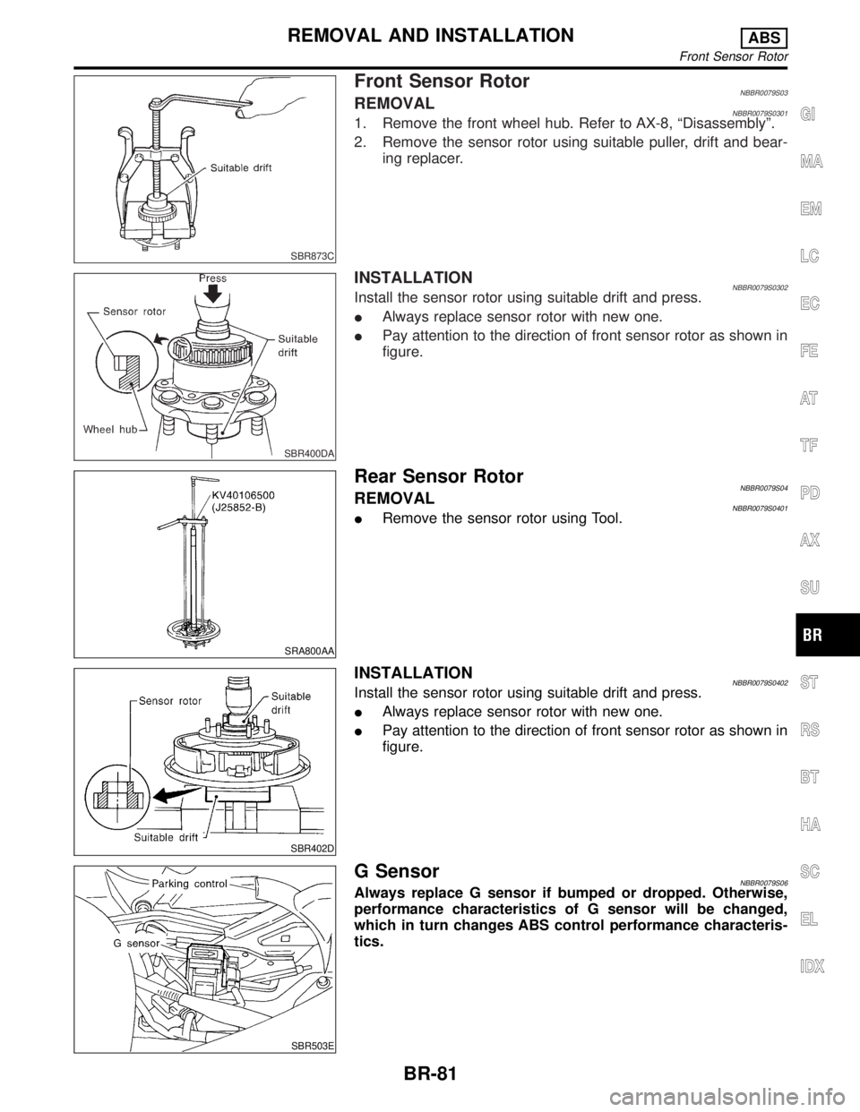
Front Sensor RotorNBBR0079S03REMOVALNBBR0079S03011. Remove the front wheel hub. Refer to AX-8, ªDisassemblyº.
2. Remove the sensor rotor using suitable puller, drift and bear-
ing replacer.
SBR400DA
INSTALLATIONNBBR0079S0302Install the sensor rotor using suitable drift and press.
IAlways replace sensor rotor with new one.
IPay attention to the direction of front sensor rotor as shown in
figure.
SRA800AA
Rear Sensor RotorNBBR0079S04REMOVALNBBR0079S0401IRemove the sensor rotor using Tool.
SBR402D
INSTALLATIONNBBR0079S0402Install the sensor rotor using suitable drift and press.
IAlways replace sensor rotor with new one.
IPay attention to the direction of front sensor rotor as shown in
figure.
SBR503E
G SensorNBBR0079S06Always replace G sensor if bumped or dropped. Otherwise,
performance characteristics of G sensor will be changed,
which in turn changes ABS control performance characteris-
tics.
GI
MA
EM
LC
EC
FE
AT
TF
PD
AX
SU
ST
RS
BT
HA
SC
EL
IDX
REMOVAL AND INSTALLATIONABS
Front Sensor Rotor
BR-81
Page 475 of 2395

Service NoticeNBBT0001IWhen removing or installing various parts, place a cloth or padding onto the vehicle body to prevent
scratches.
IHandle trim, molding, instruments, grille, etc. carefully during removing or installing. Be careful not to soil
or damage them.
IApply sealing compound where necessary when installing parts.
IWhen applying sealing compound, be careful that the sealing compound does not protrude from parts.
IWhen replacing any metal parts (for example body outer panel, members, etc.), be sure to take rust pre-
vention measures.
Supplemental Restraint System (SRS) ªAIR
BAGº and ªSEAT BELT PRE-TENSIONERº
NBBT0002The Supplemental Restraint System such as ªAIR BAGº and ªSEAT BELT PRE-TENSIONERº used along with
a seat belt, helps to reduce the risk or severity of injury to the driver and front passenger for certain types of
collision. The SRS system composition which is available to INFINITI QX4 is as follows:
IFor a frontal collision
The Supplemental Restraint System consists of driver air bag module (located in the center of the steer-
ing wheel), front passenger air bag module (located on the instrument panel on passenger side), seat belt
pre-tensioners, a diagnosis sensor unit, warning lamp, wiring harness and spiral cable.
IFor a side collision
The Supplemental Restraint System consists of side air bag module (located in the outer side of front seat),
satellite sensor, diagnosis sensor unit (one of components of air bags for a frontal collision), wiring harness,
warning lamp (one of components of air bags for a frontal collision).
Information necessary to service the system safely is included in theRS sectionof this Service Manual.
WARNING:
ITo avoid rendering the SRS inoperative, which could increase the risk of personal injury or death
in the event of a collision which would result in air bag inflation, all maintenance must be performed
by an authorized INFINITI dealer.
IImproper maintenance, including incorrect removal and installation of the SRS, can lead to per-
sonal injury caused by unintentional activation of the system. For removal of Spiral Cable and Air
Bag Module, see the RS section.
IDo not use electrical test equipment on any circuit related to the SRS unless instructed to in this
Service Manual. Spiral cable and wiring harnesses covered with yellow insulation tape either just
before the harness connectors or for the complete harness are related to the SRS.
PRECAUTIONS
Service Notice
BT-2
Page 536 of 2395

ENGINE CONTROL SYSTEM
SECTION
EC
CONTENTS
TROUBLE DIAGNOSIS - INDEX....................................8
Alphabetical & P No. Index for DTC ...........................8
PRECAUTIONS.............................................................14
Supplemental Restraint System (SRS)²AIR
BAG²and²SEAT BELT PRE-TENSIONER².............14
Precautions for On Board Diagnostic (OBD)
System of Engine and A/T.........................................14
Engine Fuel & Emission Control System ..................15
Precautions ................................................................16
Wiring Diagrams and Trouble Diagnosis ...................17
PREPARATION.............................................................18
Special Service Tools ................................................18
Commercial Service Tools .........................................18
ENGINE AND EMISSION CONTROL OVERALL
SYSTEM.........................................................................20
Engine Control Component Parts Location ...............20
Circuit Diagram ..........................................................24
System Diagram ........................................................25
Vacuum Hose Drawing ..............................................26
System Chart .............................................................27
ENGINE AND EMISSION BASIC CONTROL
SYSTEM DESCRIPTION...............................................28
Multiport Fuel Injection (MFI) System .......................28
Electronic Ignition (EI) System ..................................30
Air Conditioning Cut Control ......................................31
Fuel Cut Control (at no load & high engine
speed) ........................................................................32
Evaporative Emission System ...................................32
Positive Crankcase Ventilation ..................................38
BASIC SERVICE PROCEDURE...................................39
Fuel Pressure Release ..............................................39
Fuel Pressure Check .................................................39
Fuel Pressure Regulator Check ................................40
Injector .......................................................................41
How to Check Idle Speed and Ignition Timing ..........42
Idle Speed/Ignition Timing/Idle Mixture Ratio
Adjustment .................................................................43
Idle Air Volume Learning ...........................................57ON BOARD DIAGNOSTIC SYSTEM
DESCRIPTION...............................................................59
Introduction ................................................................59
Two Trip Detection Logic ...........................................59
Emission-related Diagnostic Information ...................60
Malfunction Indicator Lamp (MIL) ..............................74
OBD System Operation Chart ...................................75
CONSULT-II ...............................................................81
Generic Scan Tool (GST) ..........................................95
TROUBLE DIAGNOSIS - INTRODUCTION..................97
Introduction ................................................................97
Work Flow ..................................................................99
TROUBLE DIAGNOSIS - BASIC INSPECTION.........101
Basic Inspection.......................................................101
TROUBLE DIAGNOSIS - GENERAL
DESCRIPTION............................................................. 116
DTC Inspection Priority Chart.................................. 116
Fail-safe Chart ......................................................... 117
Symptom Matrix Chart ............................................. 118
CONSULT-II Reference Value in Data Monitor
Mode ........................................................................122
Major Sensor Reference Graph in Data Monitor
Mode ........................................................................124
ECM Terminals and Reference Value .....................127
TROUBLE DIAGNOSIS - SPECIFICATION VALUE..136
Description ...............................................................136
Testing Condition .....................................................136
Inspection Procedure ...............................................136
Diagnostic Procedure ..............................................137
TROUBLE DIAGNOSIS FOR INTERMITTENT
INCIDENT.....................................................................140
Description ...............................................................140
Diagnostic Procedure ..............................................140
TROUBLE DIAGNOSIS FOR POWER SUPPLY........141
ECM Terminals and Reference Value .....................141
Main Power Supply and Ground Circuit ..................142
DTC P0100 MASS AIR FLOW SENSOR (MAFS)......150
Component Description ...........................................150
GI
MA
EM
LC
FE
AT
TF
PD
AX
SU
BR
ST
RS
BT
HA
SC
EL
IDX