02 sensor INFINITI QX4 2001 Factory Service Manual
[x] Cancel search | Manufacturer: INFINITI, Model Year: 2001, Model line: QX4, Model: INFINITI QX4 2001Pages: 2395, PDF Size: 43.2 MB
Page 581 of 2395
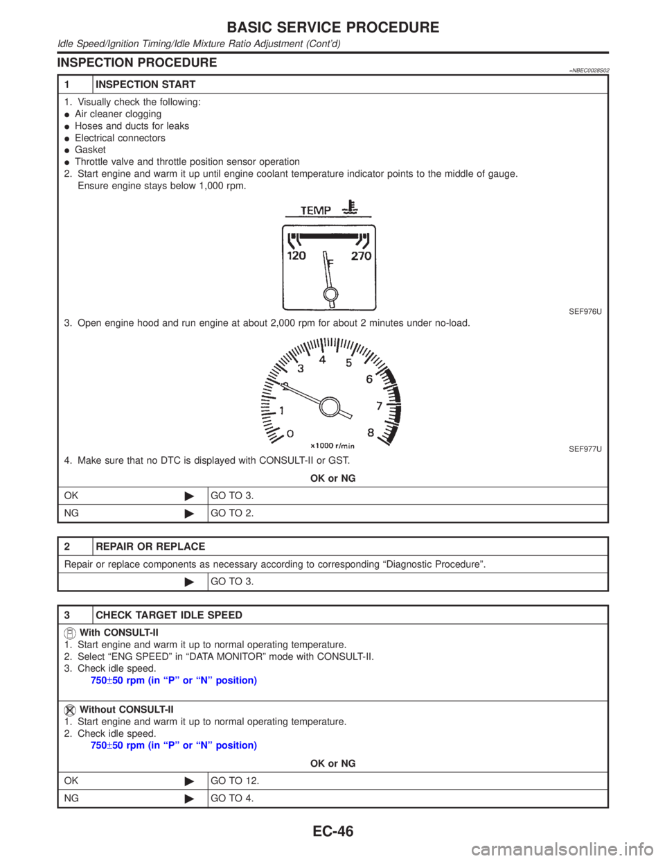
INSPECTION PROCEDURE=NBEC0028S02
1 INSPECTION START
1. Visually check the following:
IAir cleaner clogging
IHoses and ducts for leaks
IElectrical connectors
IGasket
IThrottle valve and throttle position sensor operation
2. Start engine and warm it up until engine coolant temperature indicator points to the middle of gauge.
Ensure engine stays below 1,000 rpm.
SEF976U
3. Open engine hood and run engine at about 2,000 rpm for about 2 minutes under no-load.
SEF977U
4. Make sure that no DTC is displayed with CONSULT-II or GST.
OK or NG
OK©GO TO 3.
NG©GO TO 2.
2 REPAIR OR REPLACE
Repair or replace components as necessary according to corresponding ªDiagnostic Procedureº.
©GO TO 3.
3 CHECK TARGET IDLE SPEED
With CONSULT-II
1. Start engine and warm it up to normal operating temperature.
2. Select ªENG SPEEDº in ªDATA MONITORº mode with CONSULT-II.
3. Check idle speed.
750±50 rpm (in ªPº or ªNº position)
Without CONSULT-II
1. Start engine and warm it up to normal operating temperature.
2. Check idle speed.
750±50 rpm (in ªPº or ªNº position)
OK or NG
OK©GO TO 12.
NG©GO TO 4.
BASIC SERVICE PROCEDURE
Idle Speed/Ignition Timing/Idle Mixture Ratio Adjustment (Cont'd)
EC-46
Page 585 of 2395

18 ERASE UNNECESSARY DTC
After this inspection, unnecessary DTC No. might be displayed.
Erase the stored memory in ECM and TCM (Transmission control module).
Refer to ªHOW TO ERASE EMISSION-RELATED DIAGNOSTIC INFORMATIONº, EC-72 and AT-35, ªHOW TO ERASE
DTCº.
With CONSULT-II©GO TO 19.
Without CONSULT-II©GO TO 20.
19 CHECK HEATED OXYGEN SENSOR 1 (FRONT) (BANK 2) SIGNAL
With CONSULT-II
1. Run engine at about 2,000 rpm for about 2 minutes under no-load.
2. See ªHO2S1 MNTR (B2)º in ªDATA MONITORº mode.
3. Running engine at 2,000 rpm under no-load (engine is warmed up to normal operating temperature.), check that the
monitor fluctuates between ªLEANº and ªRICHº more than 5 times during 10 seconds.
SEF945Y
OK or NG
OK©GO TO 23.
NG (Monitor does not
fluctuate.)©GO TO 28.
NG (Monitor fluctuates
less than 5 times.)©GO TO 21.
20 CHECK HEATED OXYGEN SENSOR 1 (FRONT) (BANK 2) SIGNAL
Without CONSULT-II
1. Run engine at about 2,000 rpm for about 2 minutes under no-load.
2. Set voltmeter probe between ECM terminal 62 and ground.
3. Make sure that the voltage fluctuates between 0 - 0.3V and 0.6 - 1.0V more than 5 times during 10 seconds at 2,000
rpm.
1 time: 0 - 0.3V®0.6 - 1.0V®0 - 0.3V
2 times: 0 - 0.3V®0.6 - 1.0V®0 - 0.3V®0.6 - 1.0V®0 - 0.3V
OK or NG
OK©GO TO 23.
NG (Voltage does not
fluctuate.)©GO TO 28.
NG (Voltage fluctuates
less than 5 times.)©GO TO 21.
BASIC SERVICE PROCEDURE
Idle Speed/Ignition Timing/Idle Mixture Ratio Adjustment (Cont'd)
EC-50
Page 586 of 2395
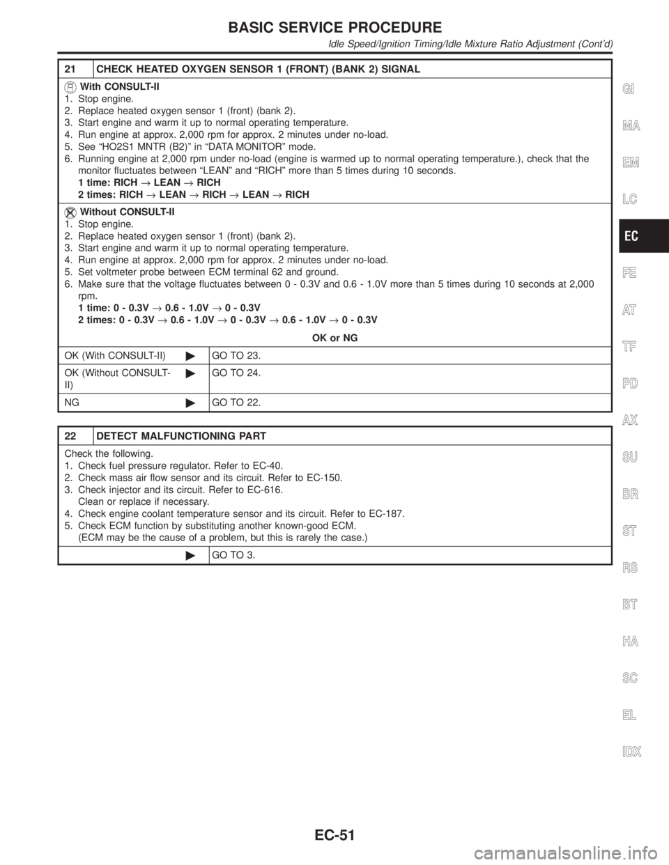
21 CHECK HEATED OXYGEN SENSOR 1 (FRONT) (BANK 2) SIGNAL
With CONSULT-II
1. Stop engine.
2. Replace heated oxygen sensor 1 (front) (bank 2).
3. Start engine and warm it up to normal operating temperature.
4. Run engine at approx. 2,000 rpm for approx. 2 minutes under no-load.
5. See ªHO2S1 MNTR (B2)º in ªDATA MONITORº mode.
6. Running engine at 2,000 rpm under no-load (engine is warmed up to normal operating temperature.), check that the
monitor fluctuates between ªLEANº and ªRICHº more than 5 times during 10 seconds.
1 time: RICH®LEAN®RICH
2 times: RICH®LEAN®RICH®LEAN®RICH
Without CONSULT-II
1. Stop engine.
2. Replace heated oxygen sensor 1 (front) (bank 2).
3. Start engine and warm it up to normal operating temperature.
4. Run engine at approx. 2,000 rpm for approx. 2 minutes under no-load.
5. Set voltmeter probe between ECM terminal 62 and ground.
6. Make sure that the voltage fluctuates between 0 - 0.3V and 0.6 - 1.0V more than 5 times during 10 seconds at 2,000
rpm.
1 time: 0 - 0.3V®0.6 - 1.0V®0 - 0.3V
2 times: 0 - 0.3V®0.6 - 1.0V®0 - 0.3V®0.6 - 1.0V®0 - 0.3V
OK or NG
OK (With CONSULT-II)©GO TO 23.
OK (Without CONSULT-
II)©GO TO 24.
NG©GO TO 22.
22 DETECT MALFUNCTIONING PART
Check the following.
1. Check fuel pressure regulator. Refer to EC-40.
2. Check mass air flow sensor and its circuit. Refer to EC-150.
3. Check injector and its circuit. Refer to EC-616.
Clean or replace if necessary.
4. Check engine coolant temperature sensor and its circuit. Refer to EC-187.
5. Check ECM function by substituting another known-good ECM.
(ECM may be the cause of a problem, but this is rarely the case.)
©GO TO 3.
GI
MA
EM
LC
FE
AT
TF
PD
AX
SU
BR
ST
RS
BT
HA
SC
EL
IDX
BASIC SERVICE PROCEDURE
Idle Speed/Ignition Timing/Idle Mixture Ratio Adjustment (Cont'd)
EC-51
Page 587 of 2395

23 CHECK HEATED OXYGEN SENSOR 1 (FRONT) (BANK 1) SIGNAL
With CONSULT-II
1. See ªHO2S1 MNTR (B1)º in ªDATA MONITORº mode.
2. Maintaining engine at 2,000 rpm under no-load (engine is warmed up to normal operating temperature.), check that the
monitor fluctuates between ªLEANº and ªRICHº more than 5 times during 10 seconds.
SEF945Y
OK or NG
OK©INSPECTION END
NG (Monitor does not
fluctuate.)©GO TO 27.
NG (Monitor fluctuates
less than 5 times.)©GO TO 25.
24 CHECK HEATED OXYGEN SENSOR 1 (FRONT) (BANK 1) SIGNAL
Without CONSULT-II
1. Set voltmeter probe between ECM terminal 63 and ground.
2. Make sure that the voltage fluctuates between 0 - 0.3V and 0.6 - 1.0V more than 5 times during 10 seconds at 2,000
rpm.
1 time: 0 - 0.3V®0.6 - 1.0V®0 - 0.3V
2 times: 0 - 0.3V®0.6 - 1.0V®0 - 0.3V®0.6 - 1.0V®0 - 0.3V
OK or NG
OK©INSPECTION END
NG (Voltage does not
fluctuate.)©GO TO 27.
NG (Voltage fluctuates
less than 5 times.)©GO TO 25.
BASIC SERVICE PROCEDURE
Idle Speed/Ignition Timing/Idle Mixture Ratio Adjustment (Cont'd)
EC-52
Page 588 of 2395
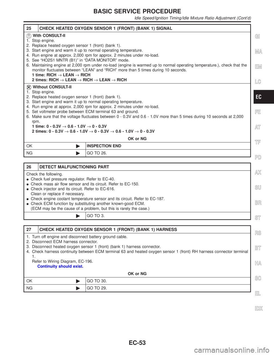
25 CHECK HEATED OXYGEN SENSOR 1 (FRONT) (BANK 1) SIGNAL
With CONSULT-II
1. Stop engine.
2. Replace heated oxygen sensor 1 (front) (bank 1).
3. Start engine and warm it up to normal operating temperature.
4. Run engine at approx. 2,000 rpm for approx. 2 minutes under no-load.
5. See ªHO2S1 MNTR (B1)º in ªDATA MONITORº mode.
6. Maintaining engine at 2,000 rpm under no-load (engine is warmed up to normal operating temperature.), check that the
monitor fluctuates between ªLEANº and ªRICHº more than 5 times during 10 seconds.
1 time: RICH®LEAN®RICH
2 times: RICH®LEAN®RICH®LEAN®RICH
Without CONSULT-II
1. Stop engine.
2. Replace heated oxygen sensor 1 (front) (bank 1).
3. Start engine and warm it up to normal operating temperature.
4. Run engine at approx. 2,000 rpm for approx. 2 minutes under no-load.
5. Set voltmeter probe between ECM terminal 63 and ground.
6. Make sure that the voltage fluctuates between 0 - 0.3V and 0.6 - 1.0V more than 5 times during 10 seconds at 2,000
rpm.
1 time: 0 - 0.3V®0.6 - 1.0V®0 - 0.3V
2 times: 0 - 0.3V®0.6 - 1.0V®0 - 0.3V®0.6 - 1.0V®0 - 0.3V
OK or NG
OK©INSPECTION END
NG©GO TO 26.
26 DETECT MALFUNCTIONING PART
Check the following.
ICheck fuel pressure regulator. Refer to EC-40.
ICheck mass air flow sensor and its circuit. Refer to EC-150.
ICheck injector and its circuit. Refer to EC-616.
Clean or replace if necessary.
ICheck engine coolant temperature sensor and its circuit. Refer to EC-187.
ICheck ECM function by substituting another known-good ECM.
(ECM may be the cause of a problem, but this is rarely the case.)
©GO TO 3.
27 CHECK HEATED OXYGEN SENSOR 1 (FRONT) (BANK 1) HARNESS
1. Turn off engine and disconnect battery ground cable.
2. Disconnect ECM harness connector.
3. Disconnect heated oxygen sensor 1 (front) (bank 1) harness connector.
4. Check harness continuity between ECM terminal 63 and heated oxygen sensor 1 (front) RH harness connector terminal
1.
Refer to Wiring Diagram, EC-196.
Continuity should exist.
OK or NG
OK©GO TO 30.
NG©GO TO 29.
GI
MA
EM
LC
FE
AT
TF
PD
AX
SU
BR
ST
RS
BT
HA
SC
EL
IDX
BASIC SERVICE PROCEDURE
Idle Speed/Ignition Timing/Idle Mixture Ratio Adjustment (Cont'd)
EC-53
Page 589 of 2395
28 CHECK HEATED OXYGEN SENSOR 1 (FRONT) (BANK 2) HARNESS
1. Turn off engine and disconnect battery ground cable.
2. Disconnect ECM harness connector.
3. Disconnect heated oxygen sensor 1 (front) (bank 2) harness connector.
4. Check harness continuity between ECM terminal 62 and front heated oxygen sensor LH harness connector terminal 1.
Refer to Wiring Diagram, EC-197.
Continuity should exist.
OK or NG
OK©GO TO 30.
NG©GO TO 29.
29 REPAIR OR REPLACE
Repair or replace harness between ECM and heated oxygen sensor 1 (front).
©GO TO 3.
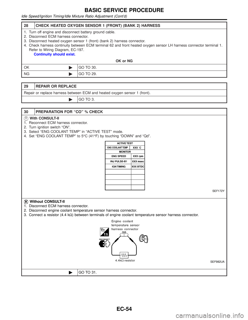
30 PREPARATION FOR ªCOº % CHECK
With CONSULT-II
1. Reconnect ECM harness connector.
2. Turn ignition switch ªONº.
3. Select ªENG COOLANT TEMPº in ªACTIVE TESTº mode.
4. Set ªENG COOLANT TEMPº to 5ÉC (41ÉF) by touching ªDOWNº and ªQdº.
SEF172Y
Without CONSULT-II
1. Disconnect ECM harness connector.
2. Disconnect engine coolant temperature sensor harness connector.
3. Connect a resistor (4.4 kW) between terminals of engine coolant temperature sensor harness connector.
SEF982UA
©GO TO 31.
BASIC SERVICE PROCEDURE
Idle Speed/Ignition Timing/Idle Mixture Ratio Adjustment (Cont'd)
EC-54
Page 590 of 2395
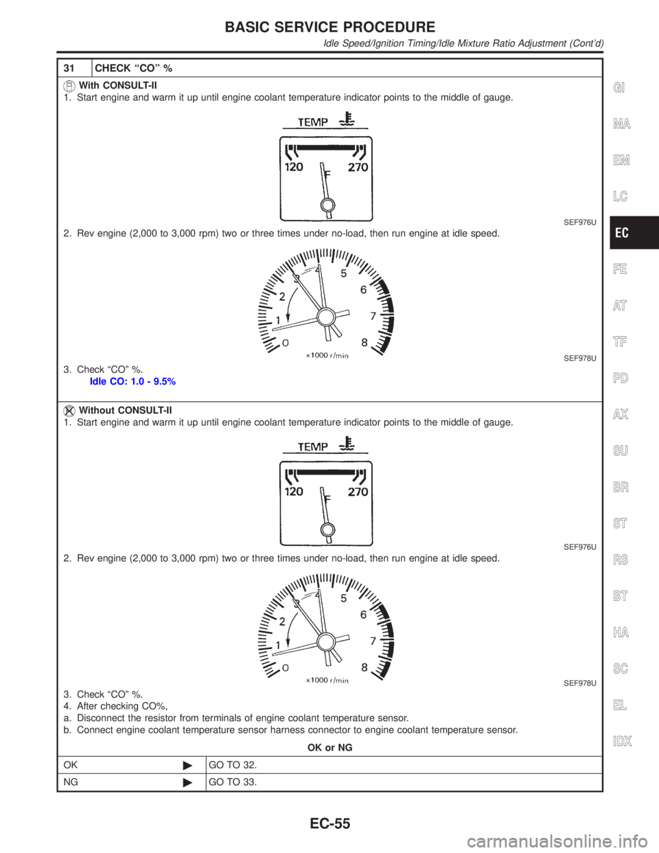
31 CHECK ªCOº %
With CONSULT-II
1. Start engine and warm it up until engine coolant temperature indicator points to the middle of gauge.
SEF976U
2. Rev engine (2,000 to 3,000 rpm) two or three times under no-load, then run engine at idle speed.
SEF978U
3. Check ªCOº %.
Idle CO: 1.0 - 9.5%
Without CONSULT-II
1. Start engine and warm it up until engine coolant temperature indicator points to the middle of gauge.
SEF976U
2. Rev engine (2,000 to 3,000 rpm) two or three times under no-load, then run engine at idle speed.
SEF978U
3. Check ªCOº %.
4. After checking CO%,
a. Disconnect the resistor from terminals of engine coolant temperature sensor.
b. Connect engine coolant temperature sensor harness connector to engine coolant temperature sensor.
OK or NG
OK©GO TO 32.
NG©GO TO 33.
GI
MA
EM
LC
FE
AT
TF
PD
AX
SU
BR
ST
RS
BT
HA
SC
EL
IDX
BASIC SERVICE PROCEDURE
Idle Speed/Ignition Timing/Idle Mixture Ratio Adjustment (Cont'd)
EC-55
Page 591 of 2395
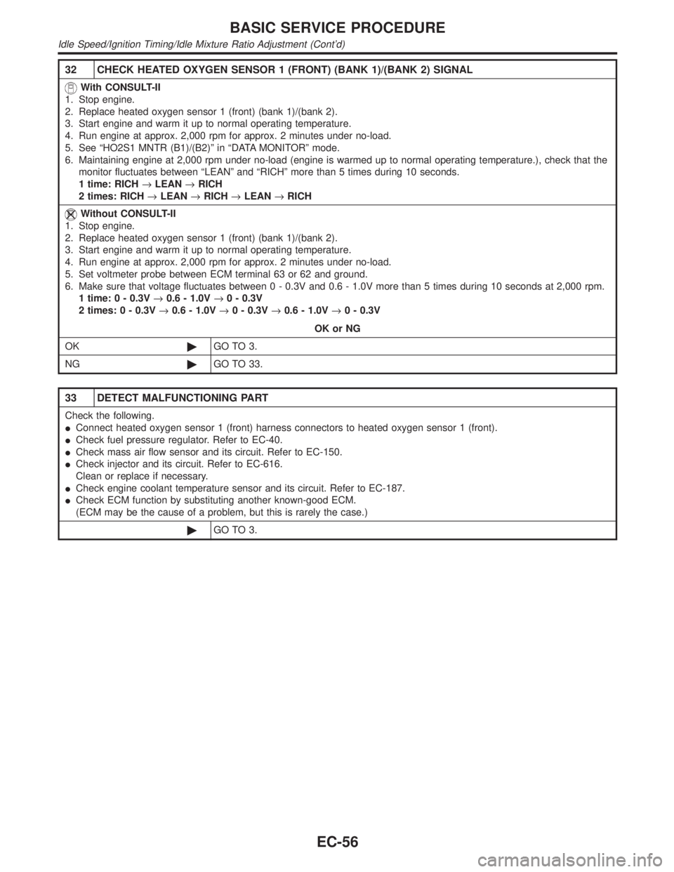
32 CHECK HEATED OXYGEN SENSOR 1 (FRONT) (BANK 1)/(BANK 2) SIGNAL
With CONSULT-II
1. Stop engine.
2. Replace heated oxygen sensor 1 (front) (bank 1)/(bank 2).
3. Start engine and warm it up to normal operating temperature.
4. Run engine at approx. 2,000 rpm for approx. 2 minutes under no-load.
5. See ªHO2S1 MNTR (B1)/(B2)º in ªDATA MONITORº mode.
6. Maintaining engine at 2,000 rpm under no-load (engine is warmed up to normal operating temperature.), check that the
monitor fluctuates between ªLEANº and ªRICHº more than 5 times during 10 seconds.
1 time: RICH®LEAN®RICH
2 times: RICH®LEAN®RICH®LEAN®RICH
Without CONSULT-II
1. Stop engine.
2. Replace heated oxygen sensor 1 (front) (bank 1)/(bank 2).
3. Start engine and warm it up to normal operating temperature.
4. Run engine at approx. 2,000 rpm for approx. 2 minutes under no-load.
5. Set voltmeter probe between ECM terminal 63 or 62 and ground.
6. Make sure that voltage fluctuates between 0 - 0.3V and 0.6 - 1.0V more than 5 times during 10 seconds at 2,000 rpm.
1 time: 0 - 0.3V®0.6 - 1.0V®0 - 0.3V
2 times: 0 - 0.3V®0.6 - 1.0V®0 - 0.3V®0.6 - 1.0V®0 - 0.3V
OK or NG
OK©GO TO 3.
NG©GO TO 33.
33 DETECT MALFUNCTIONING PART
Check the following.
IConnect heated oxygen sensor 1 (front) harness connectors to heated oxygen sensor 1 (front).
ICheck fuel pressure regulator. Refer to EC-40.
ICheck mass air flow sensor and its circuit. Refer to EC-150.
ICheck injector and its circuit. Refer to EC-616.
Clean or replace if necessary.
ICheck engine coolant temperature sensor and its circuit. Refer to EC-187.
ICheck ECM function by substituting another known-good ECM.
(ECM may be the cause of a problem, but this is rarely the case.)
©GO TO 3.
BASIC SERVICE PROCEDURE
Idle Speed/Ignition Timing/Idle Mixture Ratio Adjustment (Cont'd)
EC-56
Page 593 of 2395

SEF944Y
Without CONSULT-IINBEC0642S03021. Turn ignition switch ªONº and wait at least 1 second.
2. Turn ignition switch ªOFFº and wait at least 10 seconds.
3. Start engine and warm it up to normal operating temperature.
4. Check that all items listed under the topic ªPRE-CONDITION-
INGº (previously mentioned) are in good order.
5. Turn ignition switch ªOFFº and wait at least 10 seconds.
6. Start the engine and let it idle for at least 30 seconds.
7. Disconnect throttle position sensor harness connector (brown),
then reconnect it within 5 seconds.
8. Wait 20 seconds.
9. Make sure that idle speed is within specifications. If not, the
result will be incomplete. In this case, find the cause of the
problem by referring to the NOTE below.
10. Rev up the engine two or three times. Make sure that idle
speed and ignition timing are within specifications.
ITEM SPECIFICATION
Idle speed 750±50 rpm (in ªPº or ªNº position)
Ignition timing 15ɱ5É BTDC (in ªPº or ªNº position)
NOTE:
If idle air volume learning cannot be performed successfully,
proceed as follows:
1)Check that throttle valve is fully closed.
2)Check PCV valve operation.
3)Check that downstream of throttle valve is free from air
leakage.
4)Adjust closed throttle position switch and reset memory.
(Refer to Basic Inspection, EC-101.)
5)When the above four items check out OK, engine compo-
nent parts and their installation condition are question-
able. Check and eliminate the cause of the problem.
It is useful to perform ªTROUBLE DIAGNOSIS Ð SPECIFI-
CATION VALUEº, EC-136.
6)If any of the following conditions occur after the engine
has started, eliminate the cause of the problem and per-
form ªIdle air volume learningº all over again:
IEngine stalls.
IErroneous idle.
IBlown fuses related to the IACV-AAC valve system.
BASIC SERVICE PROCEDURE
Idle Air Volume Learning (Cont'd)
EC-58
Page 594 of 2395
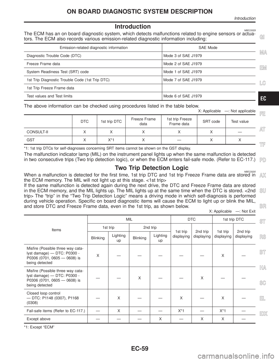
IntroductionNBEC0029The ECM has an on board diagnostic system, which detects malfunctions related to engine sensors or actua-
tors. The ECM also records various emission-related diagnostic information including:
Emission-related diagnostic information SAE Mode
Diagnostic Trouble Code (DTC) Mode 3 of SAE J1979
Freeze Frame data Mode 2 of SAE J1979
System Readiness Test (SRT) code Mode 1 of SAE J1979
1st Trip Diagnostic Trouble Code (1st Trip DTC) Mode 7 of SAE J1979
1st Trip Freeze Frame data
Test values and Test limits Mode 6 of SAE J1979
The above information can be checked using procedures listed in the table below.
X: Applicable Ð: Not applicable
DTC 1st trip DTCFreeze Frame
data1st trip Freeze
Frame dataSRT code Test value
CONSULT-II X X X X X Ð
GST X X*1 X Ð X X
*1: 1st trip DTCs for self-diagnoses concerning SRT items cannot be shown on the GST display.
The malfunction indicator lamp (MIL) on the instrument panel lights up when the same malfunction is detected
in two consecutive trips (Two trip detection logic), or when the ECM enters fail-safe mode. (Refer to EC-117.)
Two Trip Detection LogicNBEC0030When a malfunction is detected for the first time, 1st trip DTC and 1st trip Freeze Frame data are stored in
the ECM memory. The MIL will not light up at this stage. <1st trip>
If the same malfunction is detected again during the next drive, the DTC and Freeze Frame data are stored
in the ECM memory, and the MIL lights up. The MIL lights up at the same time when the DTC is stored. <2nd
trip> The ªtripº in the ªTwo Trip Detection Logicº means a driving mode in which self-diagnosis is performed
during vehicle operation. Specific on board diagnostic items will cause the ECM to light up or blink the MIL,
and store DTC and Freeze Frame data, even in the 1st trip, as shown below.
X: Applicable Ð: Not Exit
ItemsMIL DTC 1st trip DTC
1st trip 2nd trip
1st trip
displaying2nd trip
displaying1st trip
displaying2nd trip
displaying
BlinkingLighting
upBlinkingLighting
up
Misfire (Possible three way cata-
lyst damage) Ð DTC: P0300 -
P0306 (0701, 0605 Ð 0608) is
being detectedX ÐÐÐÐÐ X Ð
Misfire (Possible three way cata-
lyst damage) Ð DTC: P0300 -
P0306 (0701, 0605 Ð 0608) is
being detectedÐÐ X ÐÐ X ÐÐ
Closed loop control
Ð DTC: P1148 (0307), P1168
(0308)ÐXÐÐXÐXÐ
Fail-safe items (Refer to EC-117.) Ð X Ð Ð X*1 Ð X*1 Ð
Except above Ð Ð Ð X Ð X X Ð
*1: Except ªECMº
GI
MA
EM
LC
FE
AT
TF
PD
AX
SU
BR
ST
RS
BT
HA
SC
EL
IDX
ON BOARD DIAGNOSTIC SYSTEM DESCRIPTION
Introduction
EC-59