INFINITI QX4 2001 Factory Service Manual
QX4 2001
INFINITI
INFINITI
https://www.carmanualsonline.info/img/42/57027/w960_57027-0.png
INFINITI QX4 2001 Factory Service Manual
Page 306 of 2395
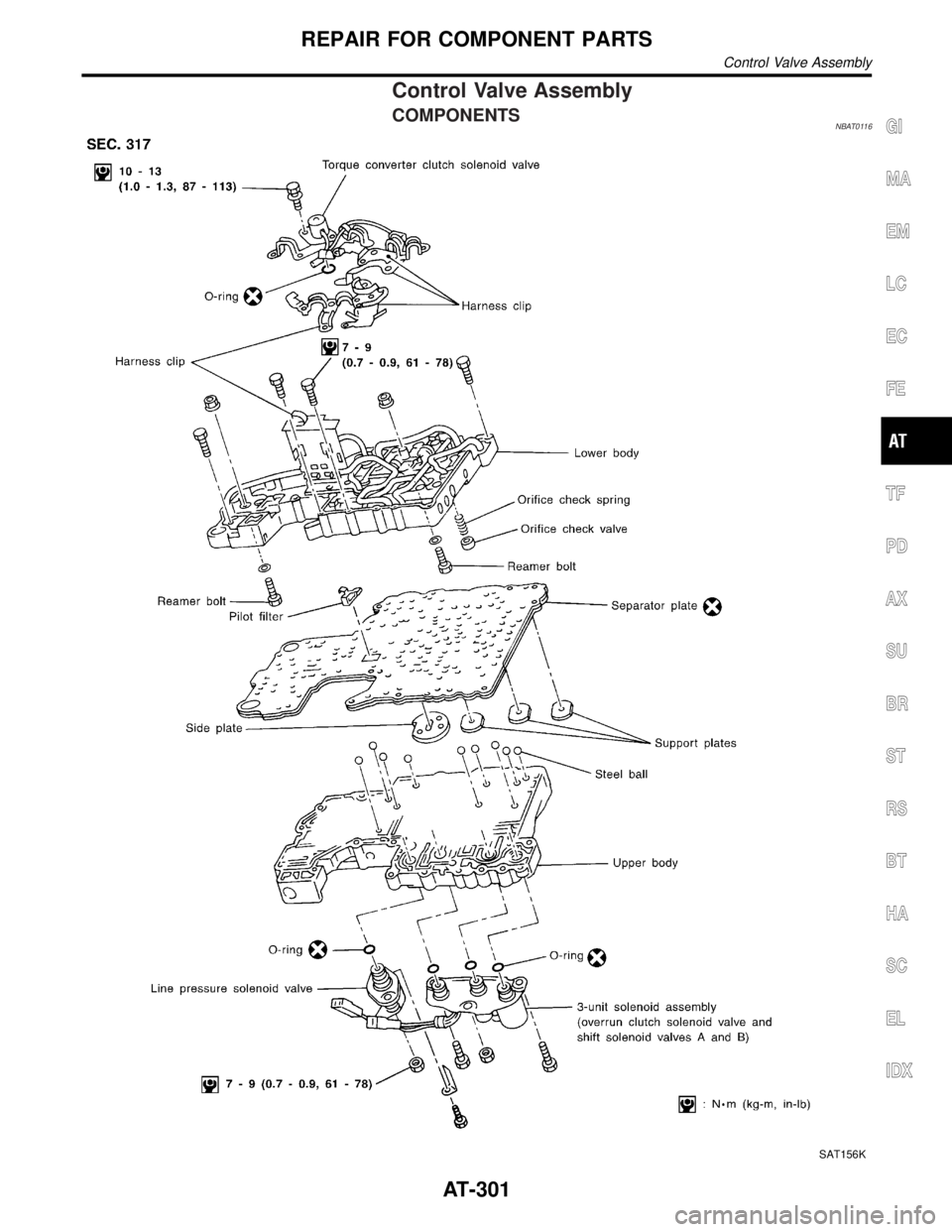
Control Valve Assembly
COMPONENTSNBAT0116
SAT156K
GI
MA
EM
LC
EC
FE
TF
PD
AX
SU
BR
ST
RS
BT
HA
SC
EL
IDX
REPAIR FOR COMPONENT PARTS
Control Valve Assembly
AT-301
Page 308 of 2395
SAT671A
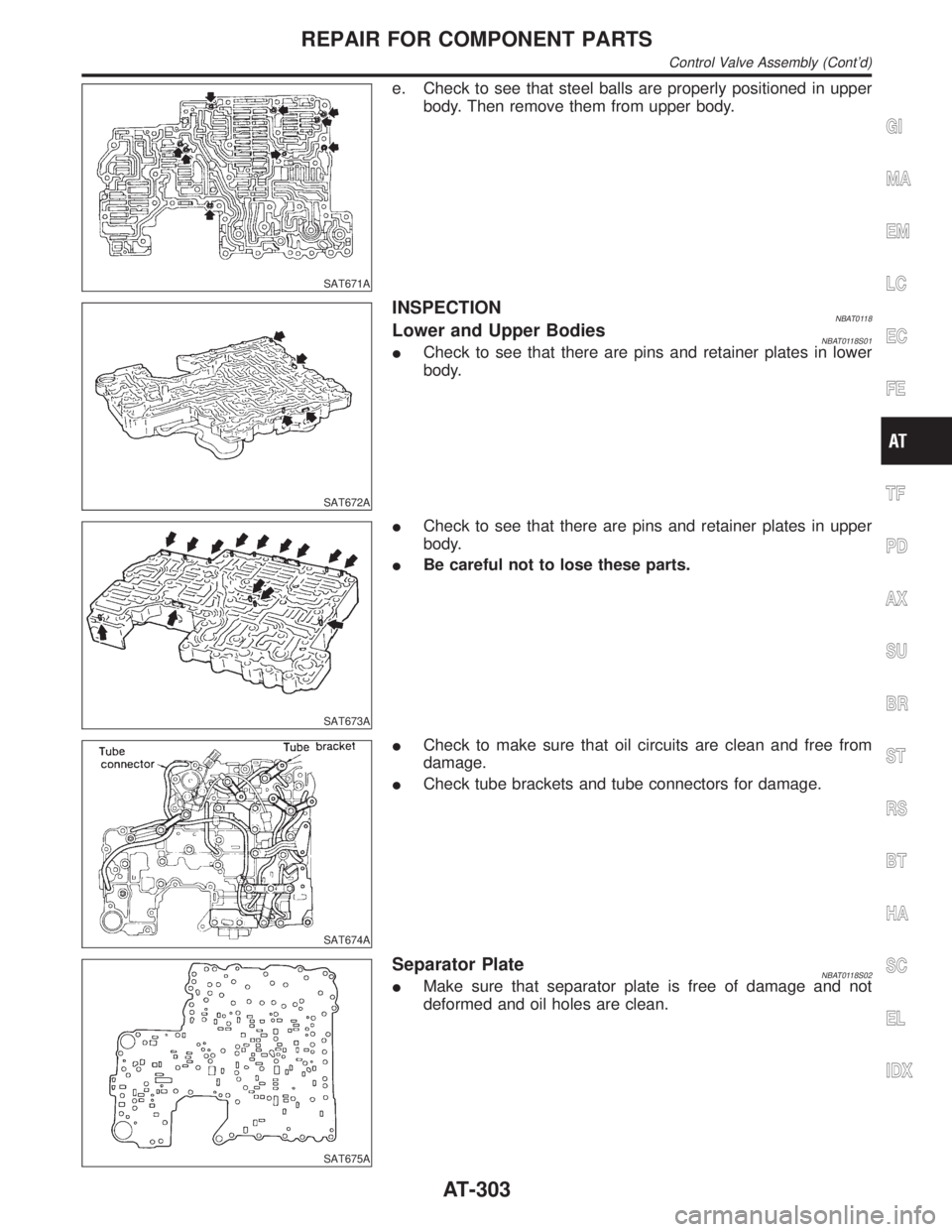
e. Check to see that steel balls are properly positioned in upper
body. Then remove them from upper body.
SAT672A
INSPECTIONNBAT0118Lower and Upper BodiesNBAT0118S01ICheck to see that there are pins and retainer plates in lower
body.
SAT673A
ICheck to see that there are pins and retainer plates in upper
body.
IBe careful not to lose these parts.
SAT674A
ICheck to make sure that oil circuits are clean and free from
damage.
ICheck tube brackets and tube connectors for damage.
SAT675A
Separator PlateNBAT0118S02IMake sure that separator plate is free of damage and not
deformed and oil holes are clean.
GI
MA
EM
LC
EC
FE
TF
PD
AX
SU
BR
ST
RS
BT
HA
SC
EL
IDX
REPAIR FOR COMPONENT PARTS
Control Valve Assembly (Cont'd)
AT-303
Page 310 of 2395
SAT681A
b. Install reamer bolts from bottom of upper body.
SAT682A
c. Place oil circuit of lower body face up. Install orifice check
spring, orifice check valve and pilot filter.
SAT197B
d. Install lower separator plate on lower body.
e. Install and temporarily tighten support plates, A/T fluid tem-
perature sensor and tube brackets.
SAT198B
f. Temporarily assemble lower and upper bodies, using reamer
bolt as a guide.
IBe careful not to dislocate or drop steel balls, orifice
check spring, orifice check valve and pilot filter.
GI
MA
EM
LC
EC
FE
TF
PD
AX
SU
BR
ST
RS
BT
HA
SC
EL
IDX
REPAIR FOR COMPONENT PARTS
Control Valve Assembly (Cont'd)
AT-305
Page 312 of 2395
Control Valve Upper Body
COMPONENTSNBAT0120
SAT142JA
Apply ATF to all components before their installation.
Numbers preceding valve springs correspond with those shown in SDS on page AT-357.
GI
MA
EM
LC
EC
FE
TF
PD
AX
SU
BR
ST
RS
BT
HA
SC
EL
IDX
REPAIR FOR COMPONENT PARTS
Control Valve Upper Body
AT-307
Page 314 of 2395
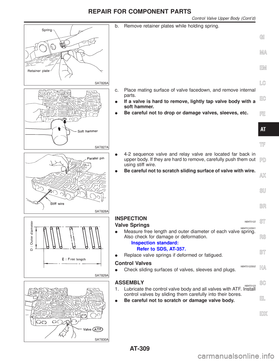
SAT826A
b. Remove retainer plates while holding spring.
SAT827A
c. Place mating surface of valve facedown, and remove internal
parts.
IIf a valve is hard to remove, lightly tap valve body with a
soft hammer.
IBe careful not to drop or damage valves, sleeves, etc.
SAT828A
I4-2 sequence valve and relay valve are located far back in
upper body. If they are hard to remove, carefully push them out
using stiff wire.
IBe careful not to scratch sliding surface of valve with wire.
SAT829A
INSPECTIONNBAT0122Valve SpringsNBAT0122S01IMeasure free length and outer diameter of each valve spring.
Also check for damage or deformation.
Inspection standard:
Refer to SDS, AT-357.
IReplace valve springs if deformed or fatigued.
Control ValvesNBAT0122S02ICheck sliding surfaces of valves, sleeves and plugs.
SAT830A
ASSEMBLYNBAT01231. Lubricate the control valve body and all valves with ATF. Install
control valves by sliding them carefully into their bores.
IBe careful not to scratch or damage valve body.
GI
MA
EM
LC
EC
FE
TF
PD
AX
SU
BR
ST
RS
BT
HA
SC
EL
IDX
REPAIR FOR COMPONENT PARTS
Control Valve Upper Body (Cont'd)
AT-309
Page 316 of 2395
SAT835A
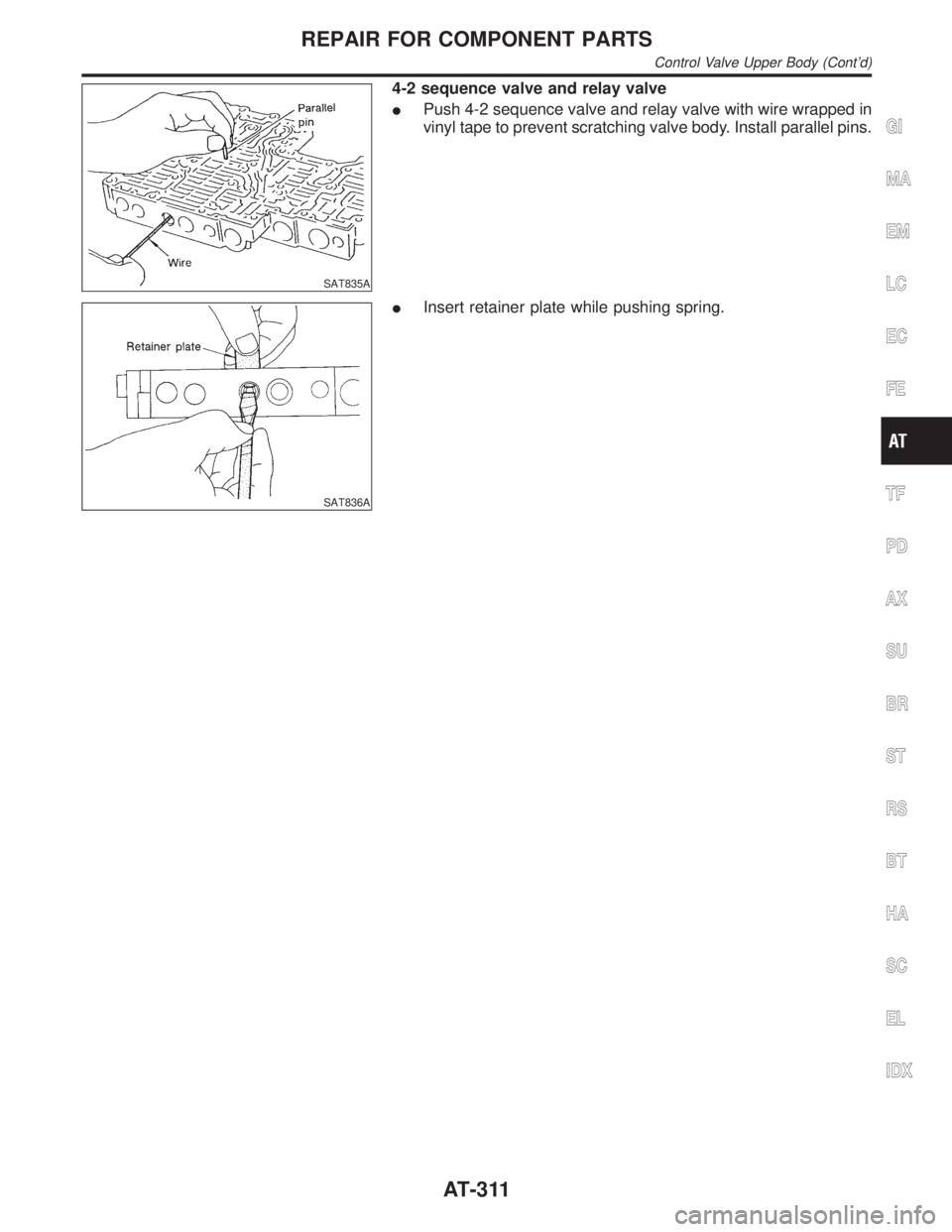
4-2 sequence valve and relay valve
IPush 4-2 sequence valve and relay valve with wire wrapped in
vinyl tape to prevent scratching valve body. Install parallel pins.
SAT836A
IInsert retainer plate while pushing spring.
GI
MA
EM
LC
EC
FE
TF
PD
AX
SU
BR
ST
RS
BT
HA
SC
EL
IDX
REPAIR FOR COMPONENT PARTS
Control Valve Upper Body (Cont'd)
AT-311
Page 318 of 2395
SAT838A
DISASSEMBLYNBAT01251. Remove valves at parallel pins.
2. Remove valves at retainer plates.
For removal procedures, refer to ªDISASSEMBLYº of Control
Valve Upper Body.
SAT829A
INSPECTIONNBAT0126Valve SpringsNBAT0126S01ICheck each valve spring for damage or deformation. Also
measure free length and outer diameter.
Inspection standard:
Refer to SDS, AT-357.
IReplace valve springs if deformed or fatigued.
Control ValvesNBAT0126S02ICheck sliding surfaces of control valves, sleeves and plugs for
damage.
SAT838A
ASSEMBLYNBAT0127IInstall control valves.
For installation procedures, refer to ªASSEMBLYº of Control
Valve Upper Body, AT-309.
GI
MA
EM
LC
EC
FE
TF
PD
AX
SU
BR
ST
RS
BT
HA
SC
EL
IDX
REPAIR FOR COMPONENT PARTS
Control Valve Lower Body (Cont'd)
AT-313
Page 320 of 2395
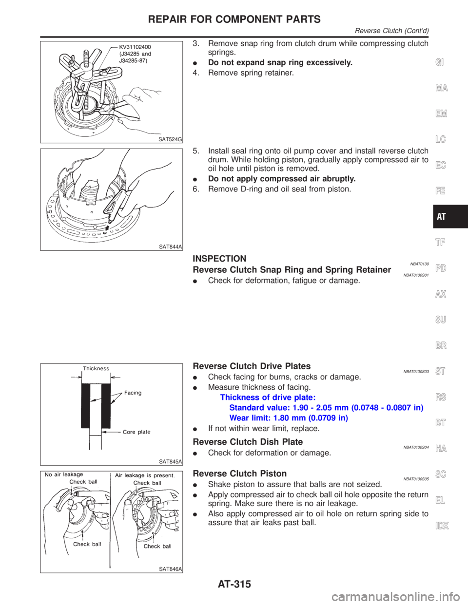
SAT524G
3. Remove snap ring from clutch drum while compressing clutch
springs.
IDo not expand snap ring excessively.
4. Remove spring retainer.
SAT844A
5. Install seal ring onto oil pump cover and install reverse clutch
drum. While holding piston, gradually apply compressed air to
oil hole until piston is removed.
IDo not apply compressed air abruptly.
6. Remove D-ring and oil seal from piston.
INSPECTIONNBAT0130Reverse Clutch Snap Ring and Spring RetainerNBAT0130S01ICheck for deformation, fatigue or damage.
SAT845A
Reverse Clutch Drive PlatesNBAT0130S03ICheck facing for burns, cracks or damage.
IMeasure thickness of facing.
Thickness of drive plate:
Standard value: 1.90 - 2.05 mm (0.0748 - 0.0807 in)
Wear limit: 1.80 mm (0.0709 in)
IIf not within wear limit, replace.
Reverse Clutch Dish PlateNBAT0130S04ICheck for deformation or damage.
SAT846A
Reverse Clutch PistonNBAT0130S05IShake piston to assure that balls are not seized.
IApply compressed air to check ball oil hole opposite the return
spring. Make sure there is no air leakage.
IAlso apply compressed air to oil hole on return spring side to
assure that air leaks past ball.
GI
MA
EM
LC
EC
FE
TF
PD
AX
SU
BR
ST
RS
BT
HA
SC
EL
IDX
REPAIR FOR COMPONENT PARTS
Reverse Clutch (Cont'd)
AT-315
Page 322 of 2395
SAT852A
7. Measure clearance between retaining plate and snap ring. If
not within allowable limit, select proper retaining plate.
Specified clearance:
Standard
0.5 - 0.8 mm (0.020 - 0.031 in)
Allowable limit
1.2 mm (0.047 in)
Retaining plate:
Refer to SDS, AT-358.
SAT841A
8. Check operation of reverse clutch.
Refer to ªDISASSEMBLYº of Reverse Clutch, AT-314.
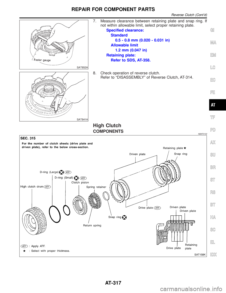
High Clutch
COMPONENTSNBAT0132
SAT158K
GI
MA
EM
LC
EC
FE
TF
PD
AX
SU
BR
ST
RS
BT
HA
SC
EL
IDX
REPAIR FOR COMPONENT PARTS
Reverse Clutch (Cont'd)
AT-317
Page 324 of 2395
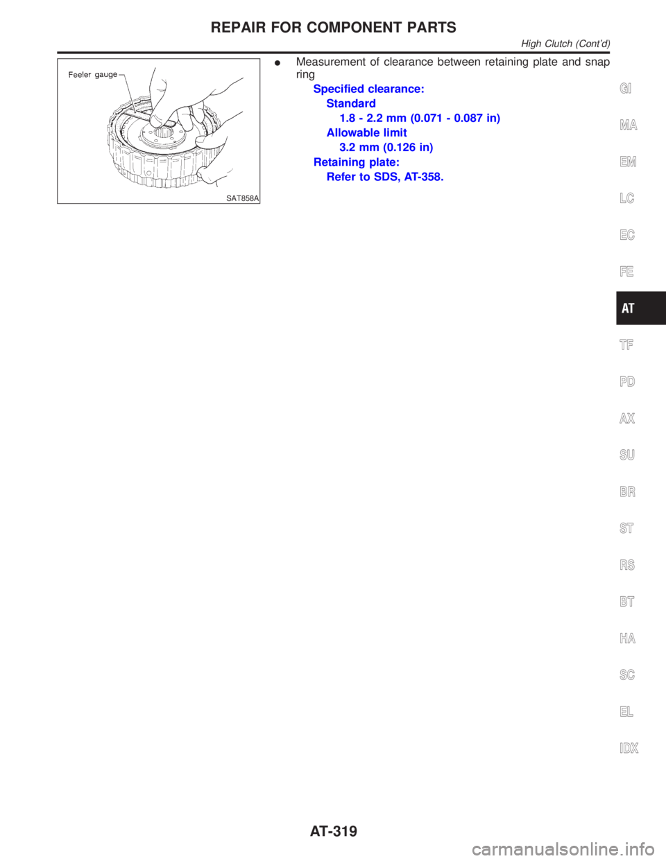
SAT858A
IMeasurement of clearance between retaining plate and snap
ring
Specified clearance:
Standard
1.8 - 2.2 mm (0.071 - 0.087 in)
Allowable limit
3.2 mm (0.126 in)
Retaining plate:
Refer to SDS, AT-358.
GI
MA
EM
LC
EC
FE
TF
PD
AX
SU
BR
ST
RS
BT
HA
SC
EL
IDX
REPAIR FOR COMPONENT PARTS
High Clutch (Cont'd)
AT-319
